 teardownit
What makes up a cable locator receiver? Which sensors are used in receivers? What is the purpose of the different types of sensors and various combinations of sensors used? How does one correctly orient the receiver to the cable being traced?
There are generally two types of sensors used in cable locator receivers: a whip antenna, also called a pole antenna (capacitive sensor), or a coil (inductive sensor). The design of a single receiver may include one or two different types of sensors. However, there are many kinds of sensors and they can be used in various combinations.
The receiver filters, amplifies, and processes the signal from the sensors and outputs it to the operator so that a decision can be made. The simplest receivers only generate an audio signal the volume of which is proportional to the level of the received electromagnetic signal. In some simple receivers, the audio signal is also supplemented by a light indicator, which further helps establish the level of the received electromagnetic signal. Obviously, these kinds of simple receivers will allow you to get reliable results only in simple cases. Their main advantages are their ease of use and low cost.
Conversely, more complex models use digital signal processing, as well as one or more sensors. Complex receivers are not limited to detecting signal strength. They can also interpret other data, such as the signal current voltage in the cable being traced, the cable depth, the direction in which the cable is located, etc. Such receivers also have multifunctional displays with an easy-to-read representation of the corresponding signal information. However, only an experienced operator that is trained to use such devices will be able to use a complex receiver effectively.
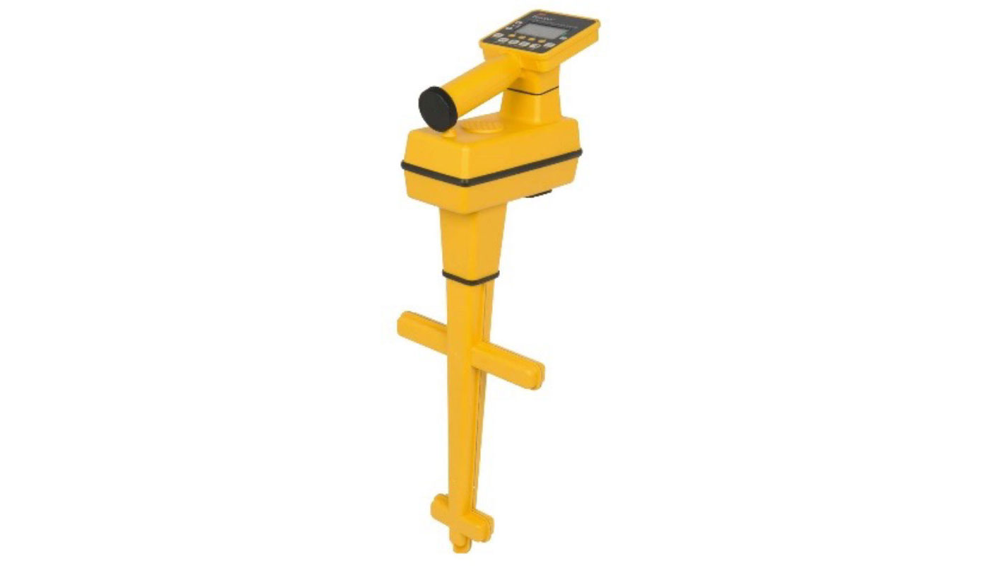
The design of the receiver depends on the purpose of the cable locator. There are several locator designs available for those used to detect underground cables or pipelines, overhead cable lines, cables in buildings, and so forth. The monoblock design is the most common. When it comes to the monoblock design, the sensors, all of the receiver's electronics, controls, and displays are housed in a single solid casing. Work in hard-to-reach places or at high elevations is often performed with the help of extended remote sensors. These sensors are sometimes attached to a boom. The monoblock design is also almost always implemented for complex receivers where several sensors are utilized simultaneously.
Most compact hand-held devices implement a whip antenna. These types of devices are usually used inside buildings. The whip antenna can be made of either a special plastic or a conductive material. In the former case, it provides safety when working on live power lines, and eliminates the possibility of accidentally short-circuiting uninsulated contacts or cable cores. In the latter case, the antenna can also be used as a contact probe, which is very convenient when working in high mounting density conditions, such as on the crossbar (MDF) or patch panels.
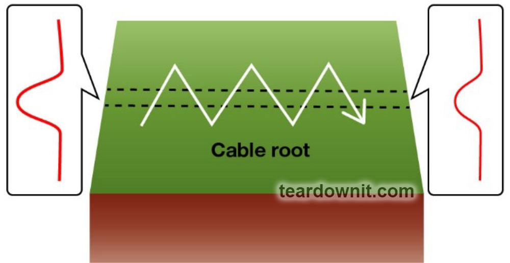
If the receiver has a whip antenna, the maximum signal strength is applied to perform the tracing. The most convenient way to perform the tracing is to zigzag the antenna along the line being traced. When the antenna passes directly over the cable, it will detect the maximum signal strength.
The axes are arranged vertically or horizontally in coils that are used as the inductive sensor. The electromagnetic field lines of the signal-carrying cable penetrate the coil differently, depending on the orientation of the coils. When the coil is passed over the cable, the magnitude of the induced signal changes. At the same time, the coordinates of signal maximums and minimums depend on the orientation of the coil.
If the coil is positioned horizontally, the maximum induced signal will be directly above the cable and is detected by its peak value. This doesn't only happen because the receiver is closest to the cable at this point, but also because the axis of the coil is parallel to the lines of the electromagnetic field.

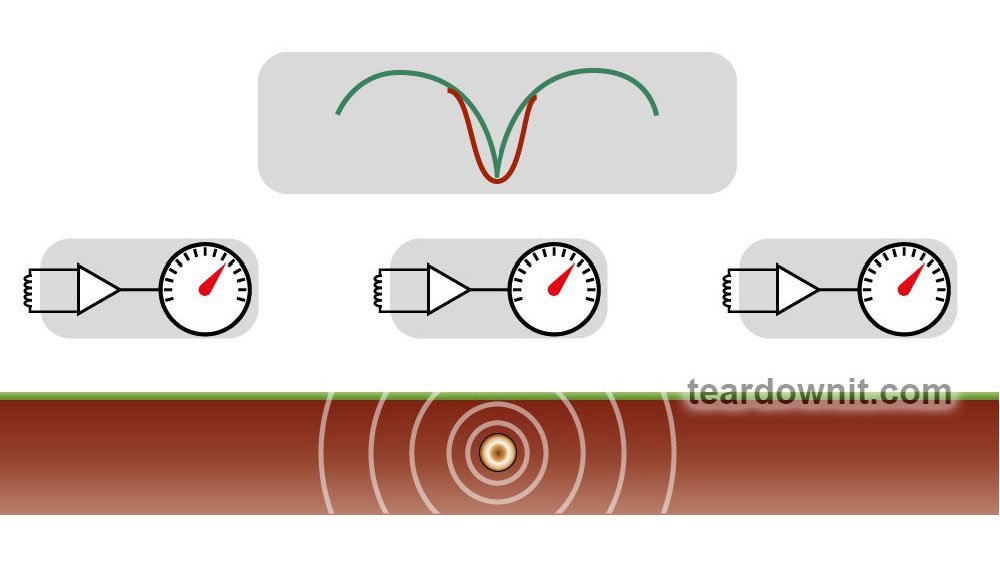
Vertical positioning of the coil gives a minimum value (nearly zero) when it is placed directly over a cable or pipeline because the electromagnetic field lines do not penetrate it. Using this method, the receiver's signal level decreases as it gets closer to the cable. When it is directly over the cable, the level of the signal (and therefore the volume level of the receiver's speaker) will be zero.
Cable tracing with a vertically-positioned coil using the zero value is much easier than peak tracing with a horizontal antenna. However, the vertical antenna is more sensitive to external interference. Generally, tracing using the zero value is a very convenient method for quick examination of the line (it is easier to distinguish the signal minimum by ear than its maximum). However, in complex cases where there are several cable lines nearby, the margin of error is much smaller when using peak tracing.

The electromagnetic field around the cable being traced can be very distorted if there is a high density of cables in the tracing area. This leads to a decrease in tracing accuracy, with a deviation of up to half a meter (one and a half feet) or even more. Thus, if each method shows a different cable location, the results generated by the peak value tracing are always more accurate than that of zero-value tracing. In the field, the 1:3 rule is a good rule of thumb to follow: if the difference between the peak and zero measurements is 8", then the cable is most likely located 2" from the peak signal location and 6" from zero signal location. Another advantage of searching with a horizontally-oriented coil using the peak value is a stronger signal at the receiver input, which is very important when working at long distances.
Both horizontal and vertical sensors have their own advantages and disadvantages. They can be implemented in the device simultaneously with the option of switching to either one as the signal source. The operator can be more confident in the accuracy of finding an underground cable when using both modes during tracing. If the locator has only one mode, it can provide very limited information. Some receivers can process the signal from the horizontal and vertical coils simultaneously. This method is called differential signaling and allows the device operator to determine the position of the sensor over the cable and the direction of the cable's location with incredible accuracy.
Discussions
Become a Hackaday.io Member
Create an account to leave a comment. Already have an account? Log In.