 teardownit
The experiment's point
LED luminaires use different connectors to connect the power supply and the light emitter or to extend the wires (for example). Manufacturers and retailers describe the current that can safely pass through the connectors for long periods.
I want to test the connectors for LED lights and strips with the maximum current. I want to measure the heating of the connectors and answer the question - "can the connectors be used at the stated/specified current for a long time." I also want to determine the critical current level at which it is dangerous to use the connector.
I want to determine the hazard by connector temperature (fire hazard) and smoke generation (poisoning hazard).
Samples
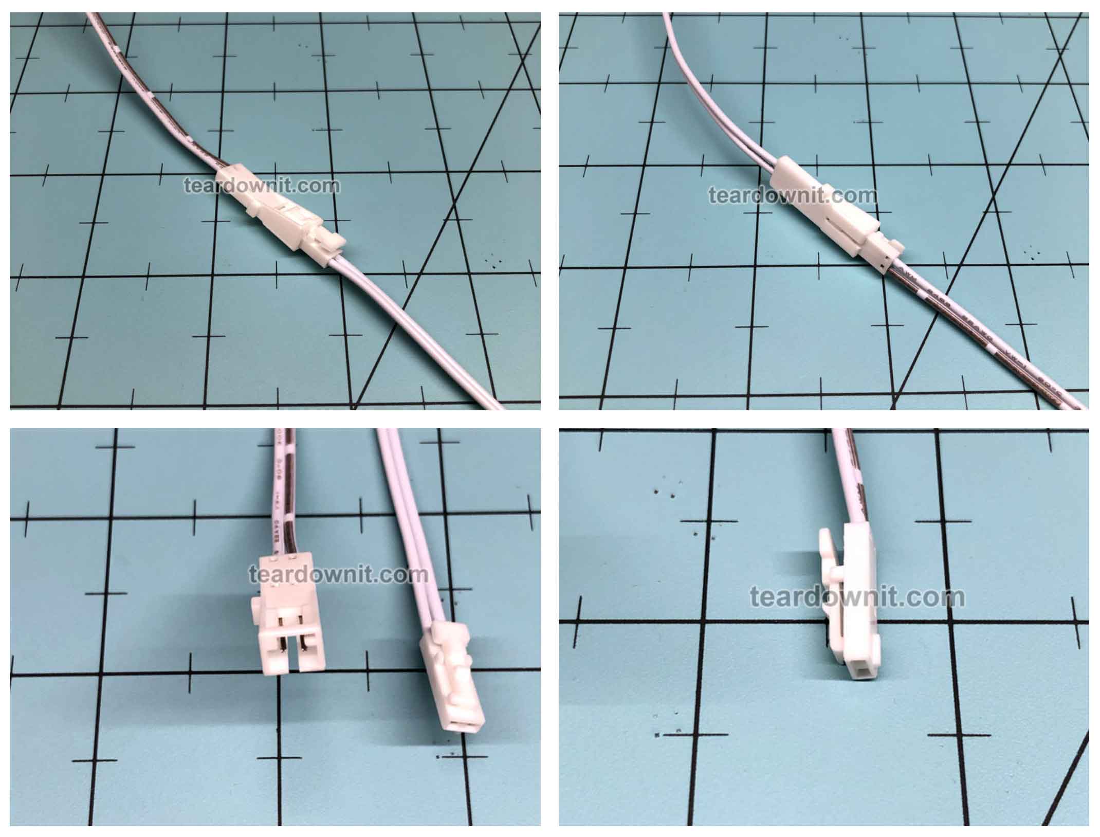
L814-L816
The first connector has different names. You can suggest variants in the comments or write me. I call this connector L814-L816 (also known as L813-815).
L814 Plug (“male”) / L816 Socket (“female”)
Max current: 3А
Wire: 22 and 24 AWG
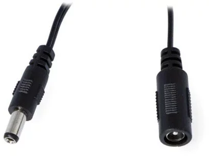
DC21-55
The second connector is known to me as DC 21-55 plug- socket (male – female).
Plug. Outer diameter: 5.5 mm / Inner diameter: 2.1 mm
Contact size: 9.5 mm
Socket. Outer diameter: 5.5 mm / Inner diameter: 2.5 mm
Contact size: 10 mm
Max. current: 5A
Wire: 18, 20, 22, 24 AWG
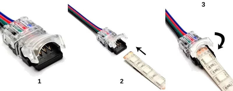
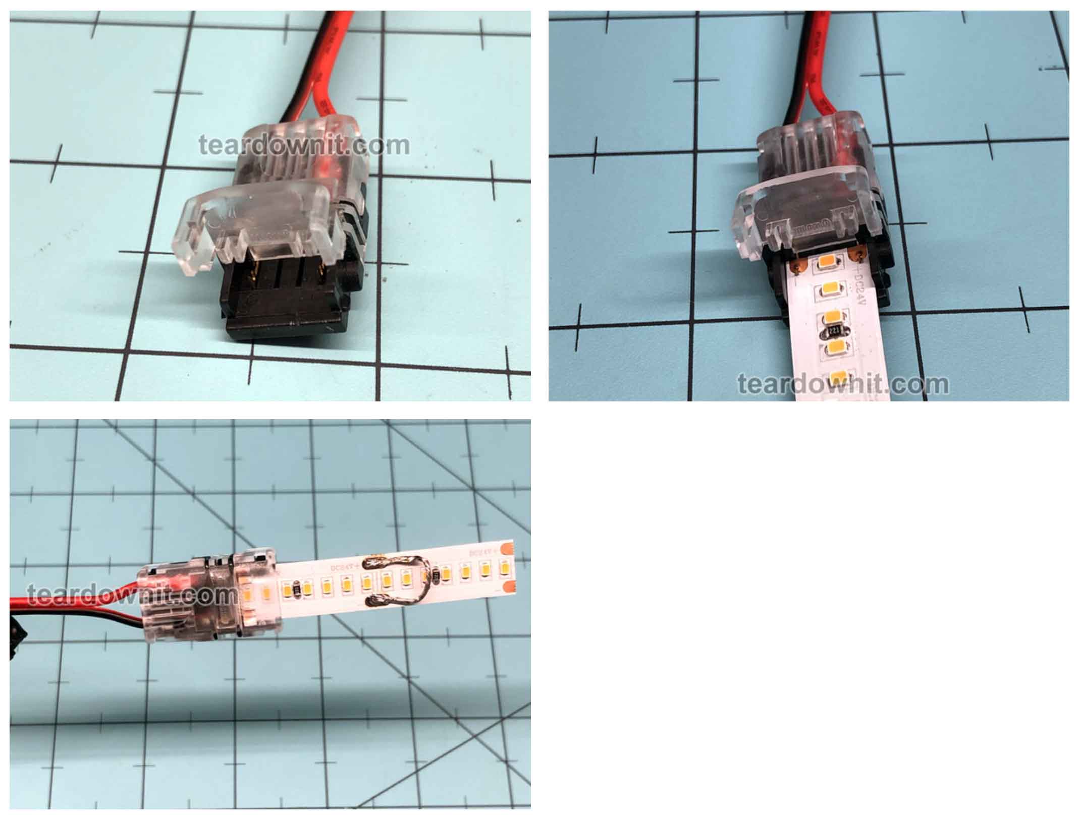
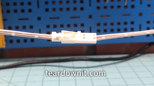
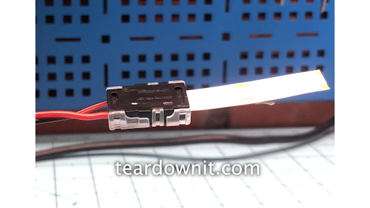
HIPPO LED STRIP CONNECTOR (WITHOUT SOLDERING)
The third connector connects directly to the LED strip without soldering.
Maximum current: 5A
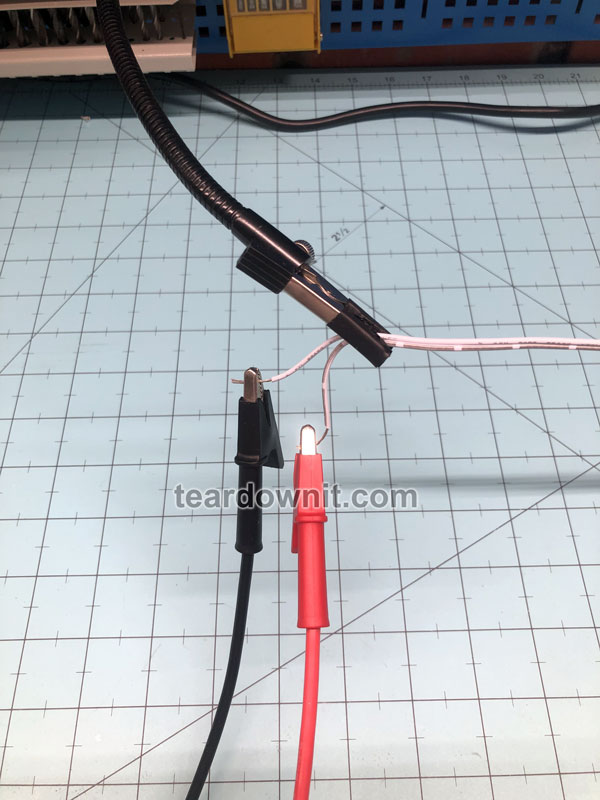
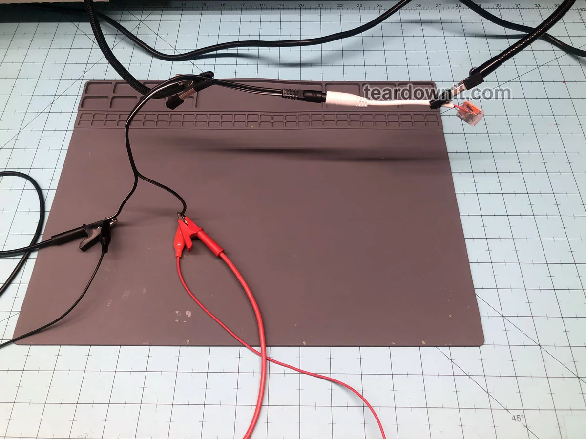
Experimental bench
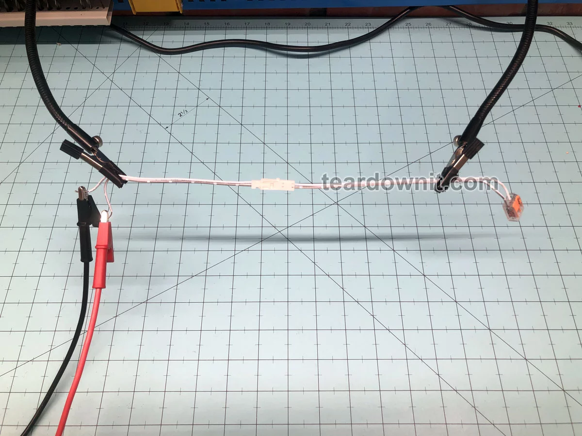
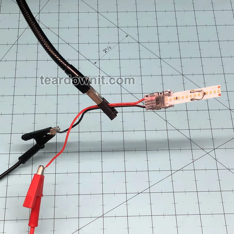
I hang the connectors and wires in the air with clamps. I short-circuit the wire on one side, and connect the other side to a powerful power supply.
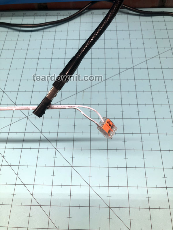
I use a piece of LED strip with a thick jumper soldered on to test the Hippo connector.
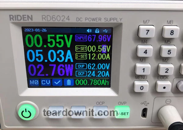
I will adjust the voltage to within 0.01 volts to get the right current level - good old Ohm's Law (I = U/R).
So.
I need a power supply. And it's the RIDEN RD6024 high precision laboratory power supply.
The integrated ammeter of this power supply will measure the current level. In my past experiments, I have verified that this is an accurate ammeter.
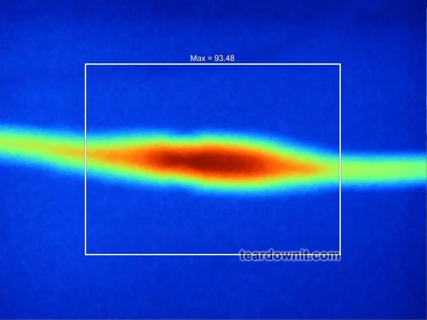
I will also use the Fluke TiS65 thermal imager (accuracy for temperature 80-1000 F = 2%) to measure the outside temperature of connectors and wires.
I will apply the required current to each sample for 30 minutes, measuring a stable temperature. I will also measure two identical samples to study the repeatability of the results.
Measurements
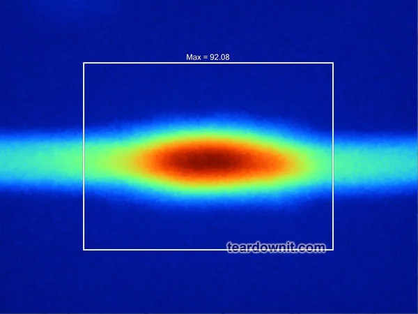
L814-L816 CONNECTOR
The connectors only heated up to 92 F at a 3A current. I measured another pair of the same connectors and got the same result. These connectors can be used at currents up to 3 Amps.
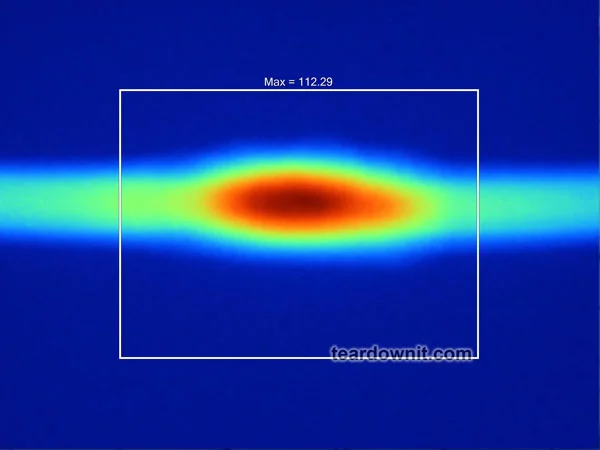
The same connectors heated up to 112 F at +50% of the maximum stated current = 4.5 Amps. Good!
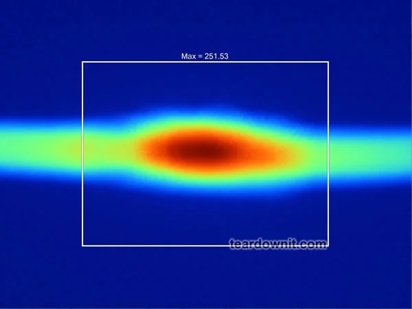
At ten amps, the connectors heated up to 251 F. They didn't collapse, but they are very hot.
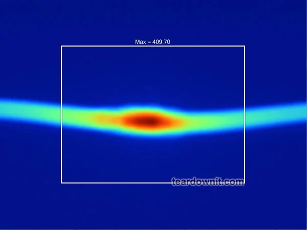
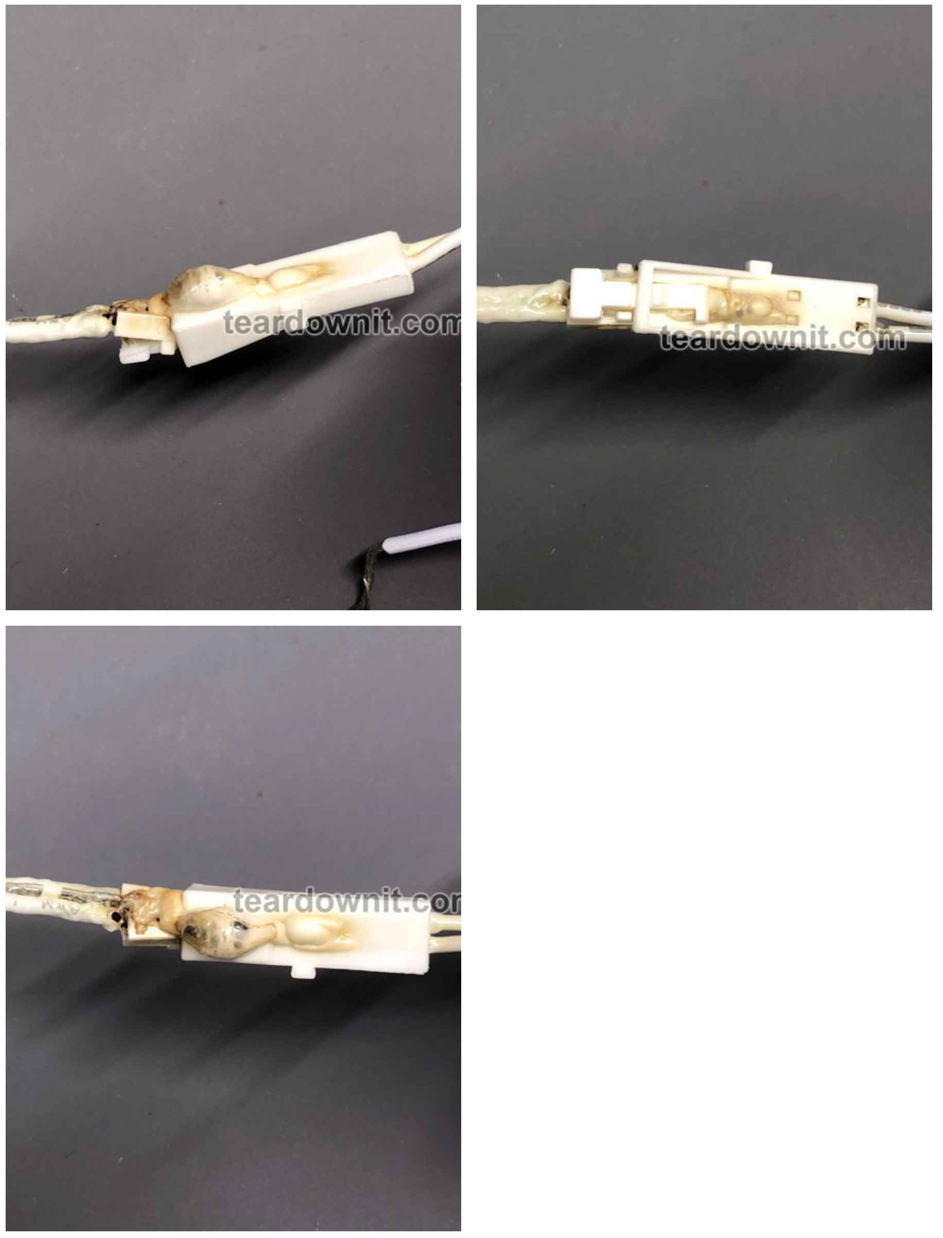
Finally, at 15 amps, the connectors quickly (1 minute) heated to 410 F and melted, producing stinky smoke.
The connectors are heated to 93 F at 5 Amps. These connectors can be used at currents up to 5 Amps.
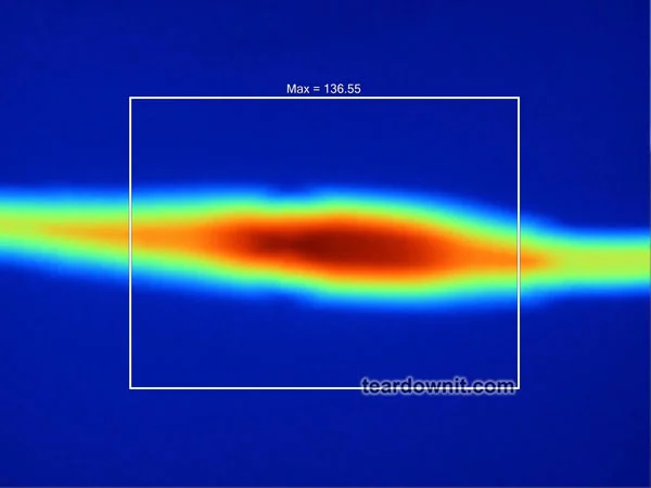
These same connectors only heated to 136 F at +100% of the maximum stated current = 10 Amps. That is an excellent reserve.
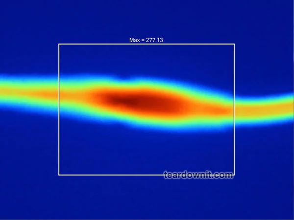
But at 15 amps, the connectors quickly heated to 277 F and melted, releasing smoke.
HIPPO LED STRIP CONNECTOR (WITHOUT SOLDERING)
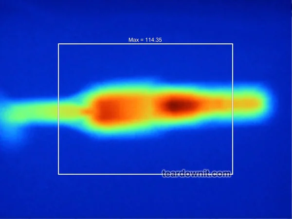
The connector only heated to 114 F at a 5 Amp current. These connectors can be used at currents up to 5 Amps.
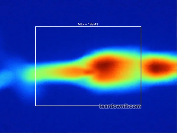
The connectors heated to 199 F at a current of +50% of the maximum stated current = 7.5 Amps.
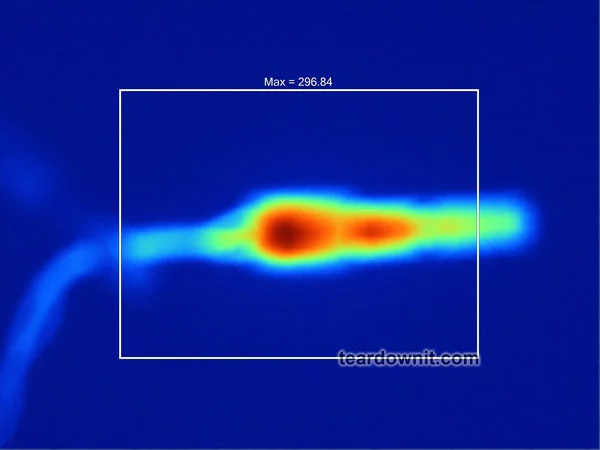
At a current of 10 amps, the connectors heated up to 297 F. The case remains intact.
At a current of 20 Amps, the temperature increased to 470 F. The connector began to melt and emit smoke.
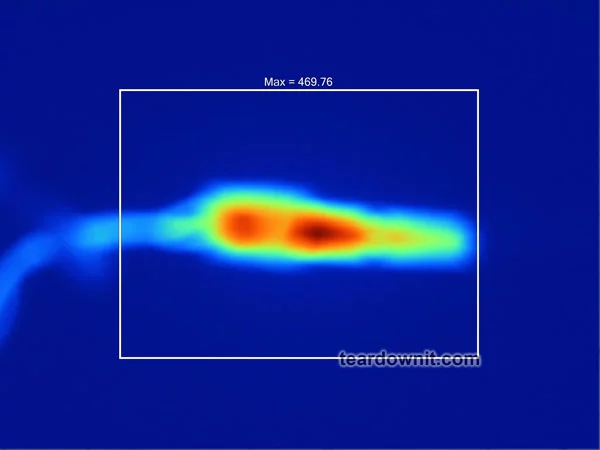
It's interesting. The heating centers are marked not in the "teeth" (places where the LED strip is pierced) of the connector but in the areas where the connector contacts the wires.
Discussions
Become a Hackaday.io Member
Create an account to leave a comment. Already have an account? Log In.