 teardownit
Wire tracing can be performed using two modes: passive and active.

The passive mode can be used to trace electrical wiring that has a current going through it. The electromagnetic field of the wire can be detected with a receiver that is equipped with either an inductive sensor (if an electric current is flowing through the wire) or a capacitive sensor (if there is no electric current present in the wire). The main disadvantage of this mode is the possibility of getting strong interference from other power lines, electrical appliances, and/or metal studs.

Therefore, the passive mode is very rarely used for tracing and identifying electrical wires when using professional devices.
During active tracing mode, a device generates a signal that is sent through the wire at a frequency different from the primary power line frequency (50/60 Hz). In this case, the signal can be sent through either a disconnected line or a live one.
Remember, conductors in the wiring cables are run in parallel. Let's assume that one sends signals through a pair of wire conductors that are opposite the line phase. In this case, the generated electromagnetic fields will be mutually compensated. Resulting electromagnetic field will be weak and hardly detectable.
For example, let's say a wire runs inside a metal cable duct. If you send a signal between one of the cable cores and this duct, mutual compensation of the signals will also be detected. It is easier to trace a wire in the points where cable cores are separated (e.g., in the switchboard, socket, or junction box). It is enough to just separate a wire pair by 1-3 cm to perform tracing. Then a signal can be sent through the wire pair as the next step.
The easiest way to trace a disconnected line is to send a generated high-frequency signal to the wire pair. Then, a capacitive sensor should be used in order to detect the generated electromagnetic field. In the case of a three-wire power line, it is recommended to use the phase-neutral wire pair. Do not use the phase-ground and neutral-ground pairs in order to avoid the risk of unwanted ground loops.
It is important to remember that the neutral wire should not be conductively-coupled with a natural grounding electrode (for example, a water supply pipe). If this is unavoidable, the signal generator can be connected to any large metal object instead of neutral (for example, the metal frame of furniture). However, the trace distance will be significantly reduced in this case.
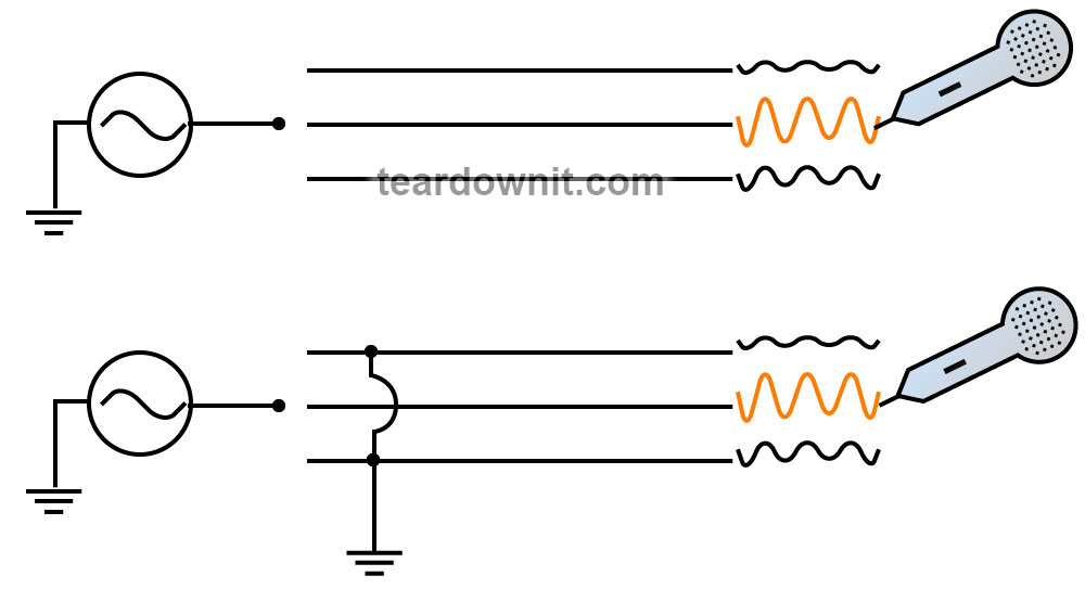
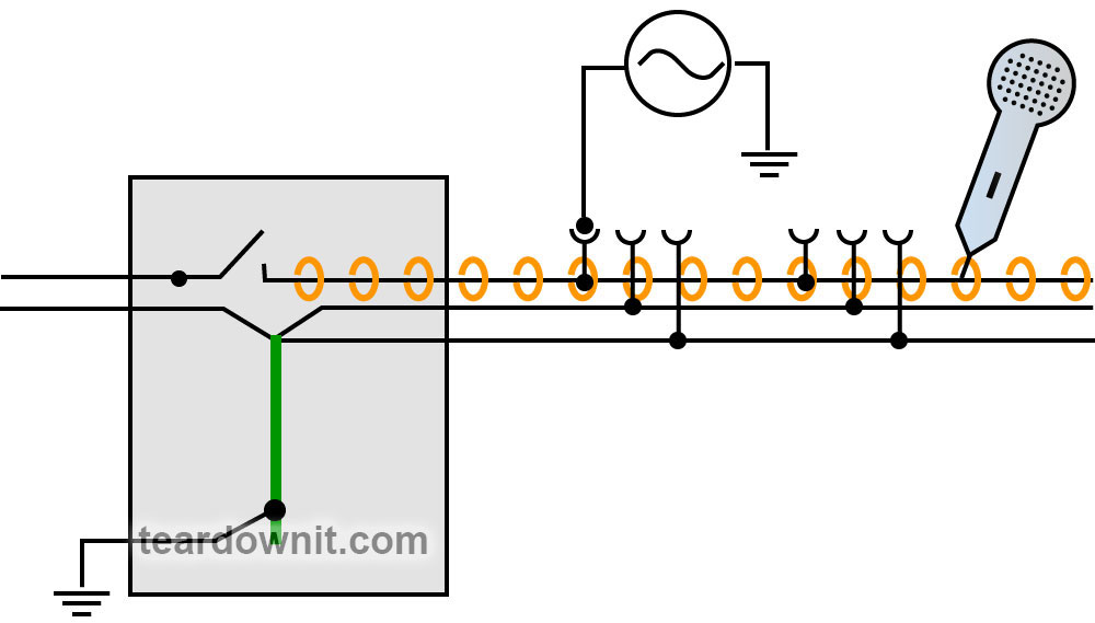
It is often necessary to identify cable wires while performing tracing. In this case, wires that are not receiving a signal should be grounded. Grounding must be provided at the signal generator connection point. This will significantly reduce the amplitude of the signal induced on the wires and make identification easier even if the cable is long.
There are three ways to send a signal to live wiring in the active tracing mode.

THE FIRST WAY
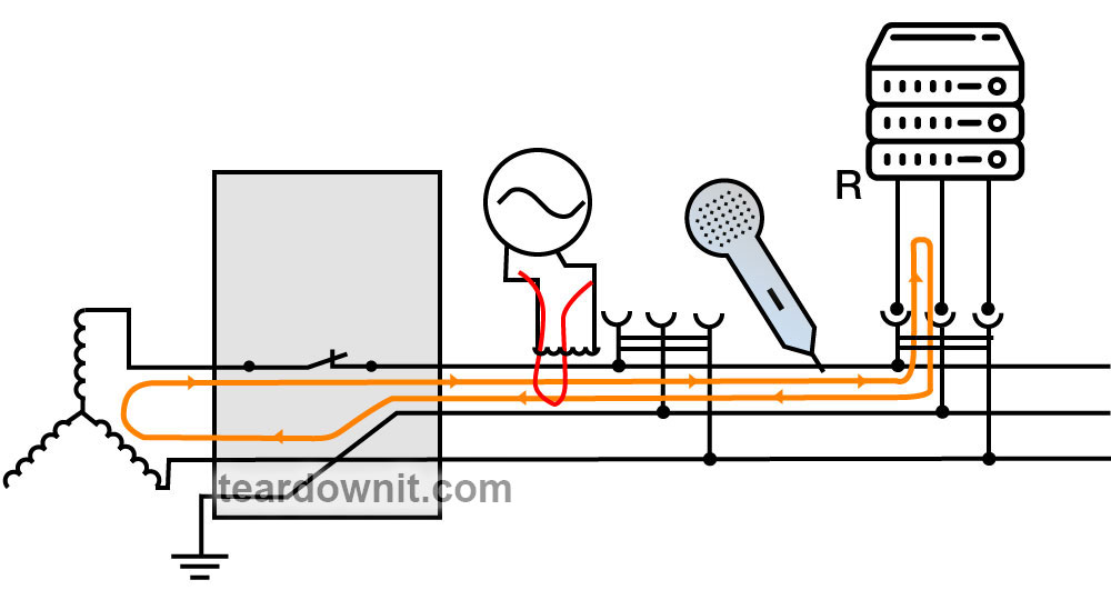
is to use a signal generator that provides resistive load with alterating resistance at a constant frequency. When you connect such a signal generator to the mains socket, the wires will start emitting a specific signal. This signal can be detected by a receiver with an inductive sensor. Moreover, the alterating resistance of the signal generator has no affect on the operation of the equipment that's connected in parallel, nor the alterating resistance of any other device.

In this case, the wiring can only be traced from a specific socket to the switch or breaker that's located inside the switchboard. However, you can find a switchboard and identify the relevant circuit breaker inside it without even performing line tracing.
The signal from such a signal generator goes from the load towards the power source. It can successfully overcome transformers. Thus, the signal amplitude varies in accordance with transformation ratio. But this signal is not passed along to circuits that are connected in parallel (e.g. other mains sockets). This hapens due to the fact that the traced signal is generated by current fluctuations caused by an alterating generator resistance.
THE SECOND WAY
is to use an induction clamp. The clamp is installed only on the phase wire conductor. The traced signal is generated by both the voltage and current fluctuations. The line is traced with the use of an inductive sensor starting from the point where the clamp is attached. Tracing can be directed to the load point (anything that consumes electricity) or to the power source.
Due to the high frequency of the signal sent, this method can be used to trace even those disconnected circuits. This is possible due to capacitive leakage current.
 THE THIRD METHOD
is based on the use of the signal generator with high-voltage capacitive decoupling. The signal generator is connected directly to any wire in the line. It generates an AC signal in the wire regardless of the circuit voltage availability. The choice of sensor depends on the signal frequency. An inductive sensor is used for low-frequency signals, while a capacitive sensor is used for high-frequency signals.
Meanwhile, if the line capacitive leakages are insufficient, then line can either be loaded or terminated at the far end.
IN CONCLUSION
it is important to note that the signal generated by a professional-grade signal generator is actually combination of three or four frequencies. This provides reliable tracing in conditions of high interferance. Signal generators that can be directly connected to powered lines can be utilized with both direct and alternating current of up to 600 V. Therefore, they are also suitable for tracing power circuits on power supply nodes.
Discussions
Become a Hackaday.io Member
Create an account to leave a comment. Already have an account? Log In.