 Joshua Beck
Something I've been meaning to do for a while, creating a new version of my lighting controller to work with my home server and cut out external dependencies.
- v1 - ATMEGA328P (Uno) + Ethernet + Android/Tasker
- Works, but fairly unreliable and can't be set remotely.
- It's a huge mess of interconnected boards.
- v2 - ESP8266 (NodeMCU) ATMEGA328 + WiFi + Thinger.io
- Soldered onto one board this time.
- Uses an external cloud service which simplifies a lot of the comms.
- Looks messy, want to clean it up a lot.
- Uses an ESP chip for the WiFi and an ATMEGA chip for running the real-time pattern code.
- v3 - ESP32 (TinyS2) + Arduino Nano + 3D printed case + WiFi + Thinger.io
- Much cleaner and integrated into a nice box.
I've got a new drive circuit and controller board and want to make a new version.
Maybe order a proper PCB and integrate it with my home server.
Also, I'd like to accurately measure the box this time and get the 3D printing right.
I've just got a few of these little PCA9685 PWM controllers:
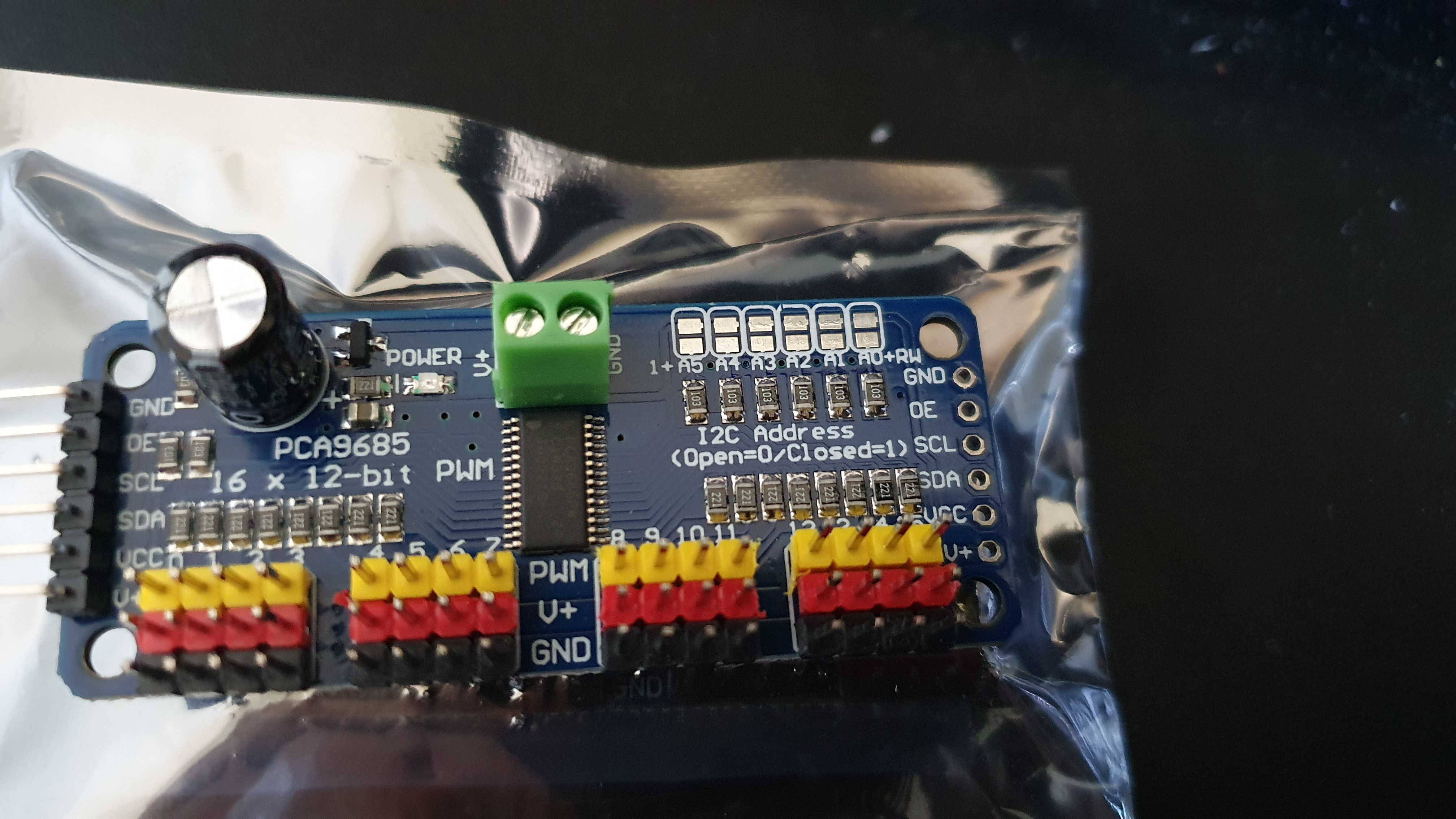
That's 16 PWM outputs easily.
I want to remove the coprocessor, but that'll involve somehow keeping the code working in real time while keeping the WiFi responsive.
I'm guessing that's going to involve a mess of RTOS stuff, hopefully, that won't force me to write the whole thing in Espressif C rather than something nice like CircuitPython. Think of the valuable hours of my life I'd waste...
So I'm guessing I can't drive very much current directly off this chip...
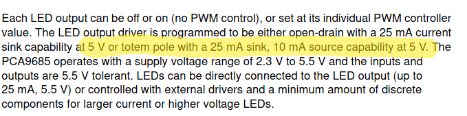
No good, I want at least 100mA per channel. That was the limit for the previous version.
Let's see what I have in the workshop.
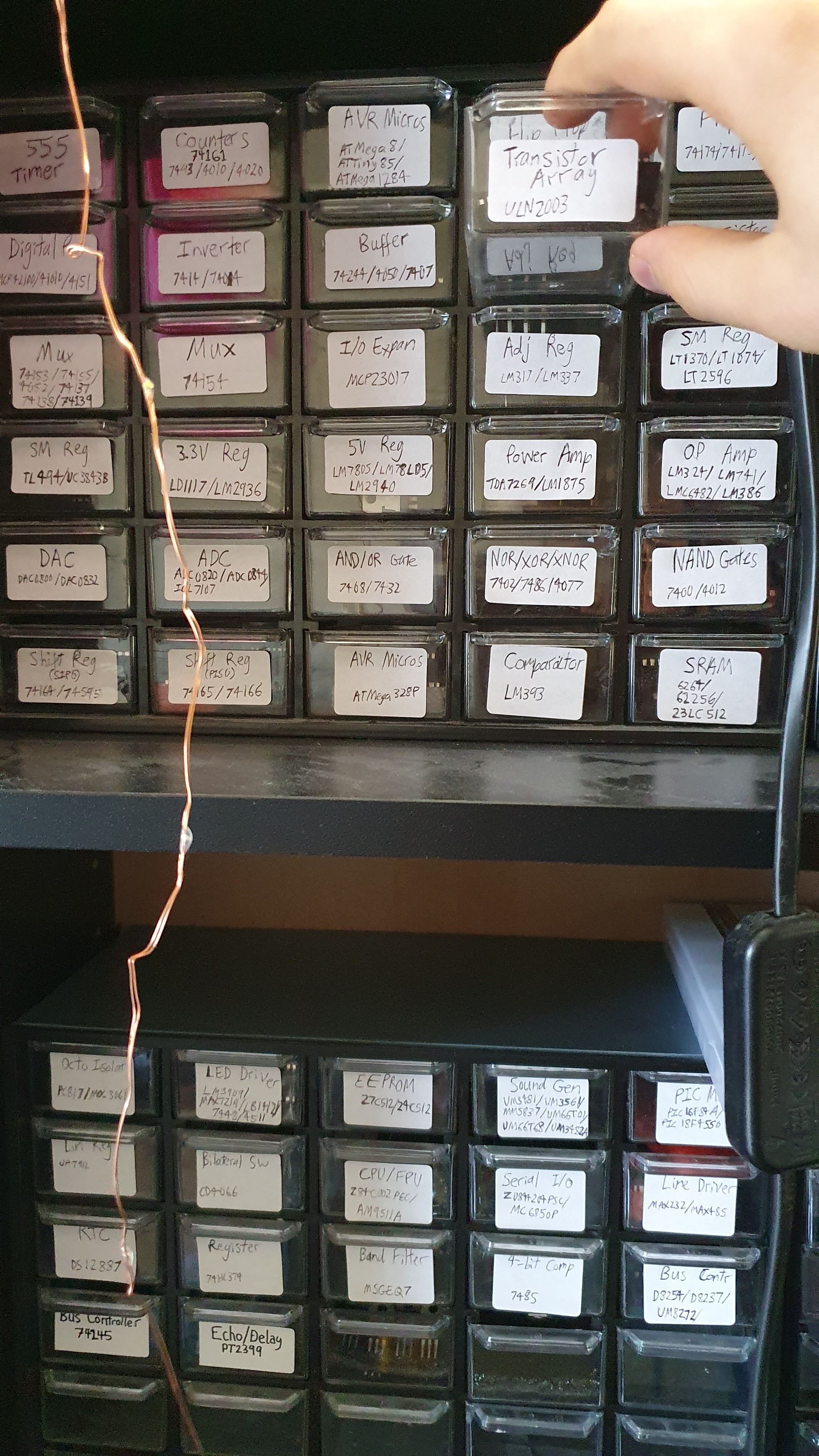
Ah, perfect.
Looks like that'll support the required 100mA per channel even with all channels running simultaneously and it should be very easy to wire.
I'll add in a TinyS2 ESP32 module and draw up a schematic for that.
Gotta love these user-supplied components. I'm eternally grateful to the people making these.
Looks like there's plenty of useful information available on Adafruit:
https://learn.adafruit.com/16-channel-pwm-servo-driver/overview
I should buy more Adafruit modules.
I'll use 3.3 volts as both the I/O and output voltage for simplicity. My current setup works at the voltage anyway.
There's no chance of the TinyS2 little linear regular providing enough power, so I'll need a power converter module.
The required current is within range of a little MP1482 module.
You can get a whole panel of these for a fairly low price.
Anyway.
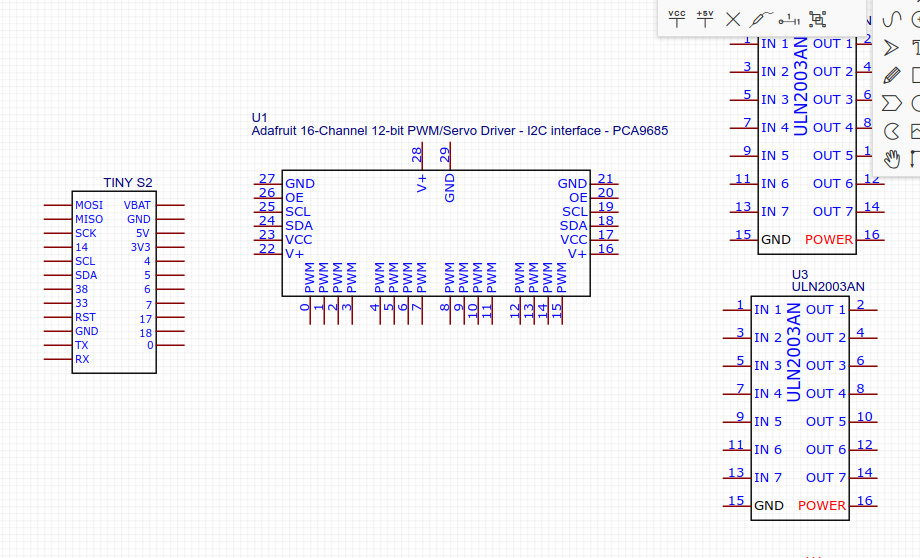
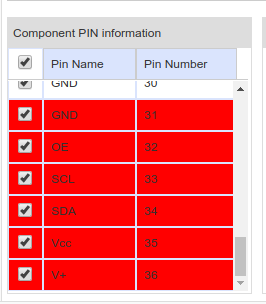
So we'll need multiple ULN2003 chips to cover all the outputs.
There are, uh, seven outputs. So that's 2.285714286 chips!
I mean three.
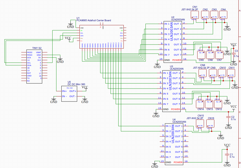
Now let's wire everything up.
Alright, looks good.
The connectors are a bit messy, but there's no surprises because we're basically just gluing modules together.
Here's a PDF link:
https://drive.google.com/file/d/1W7WFwgPljky7qHuddlNUGp8EHyyL_Ran/view?usp=share_link
Now for the wiring.
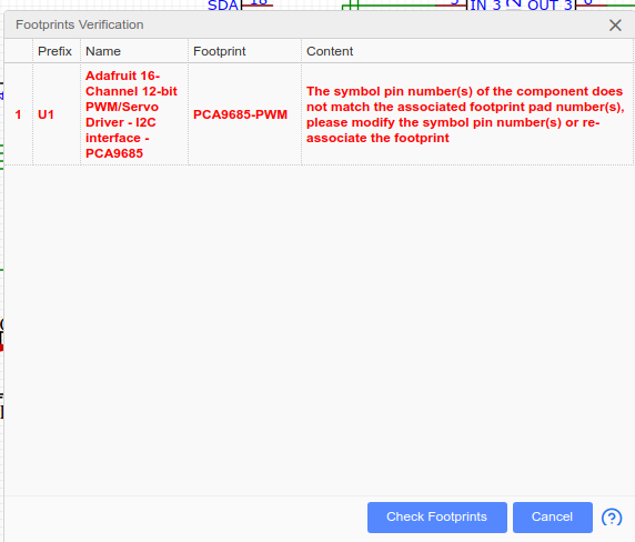
Ugh, really?
Let me swap that out real quick...
There we go.
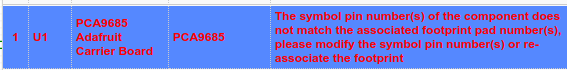
Nope. The error persists.
Oh... the problem is just in EasyEDA's imagination anyway. *sighs*
Finally got it after trying a third version of the component design.
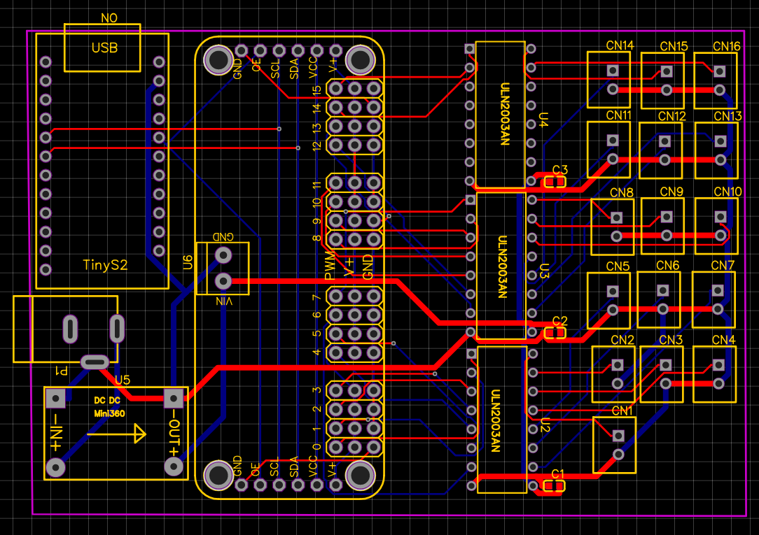
Now let's sort this mess out:
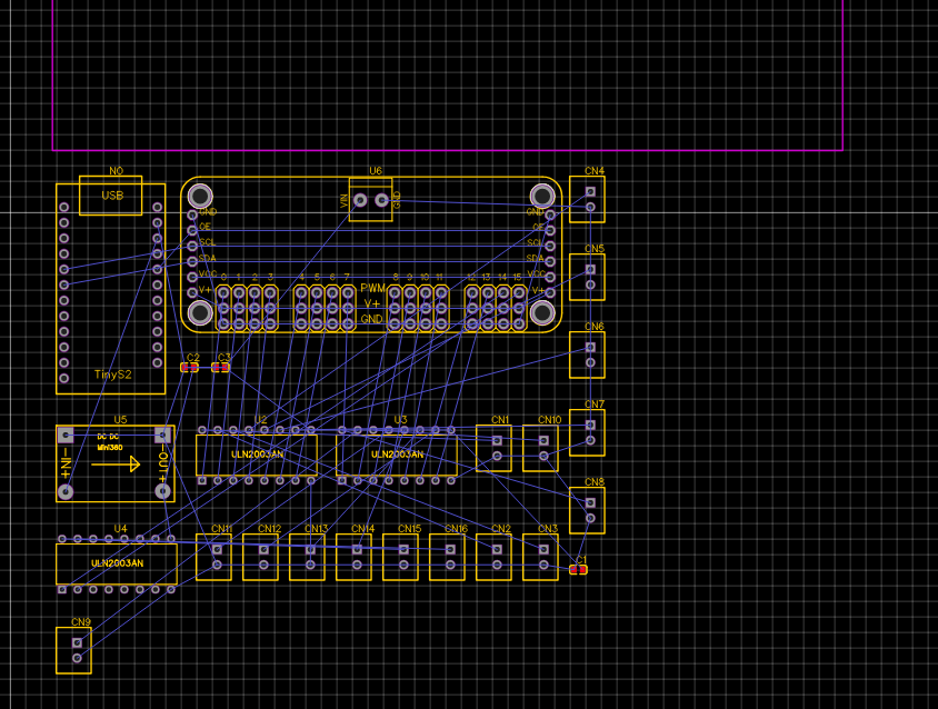 I arranged the headers into a rough grid of threes and put the other component wherever they would fit to form a nice rectangular board with minimal dimensions. I'll give the USB-C power connection a little overhang so it can reach outside the housing.
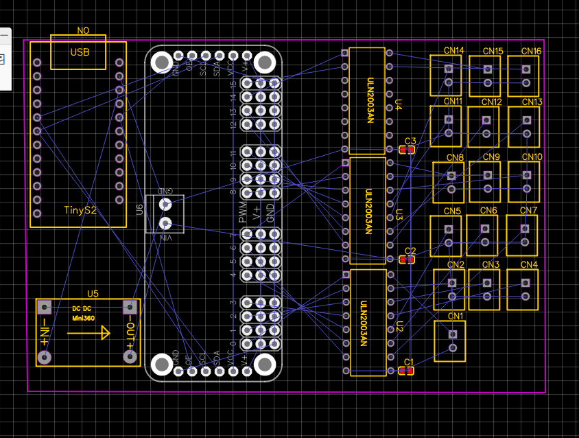
Autorouter, go!
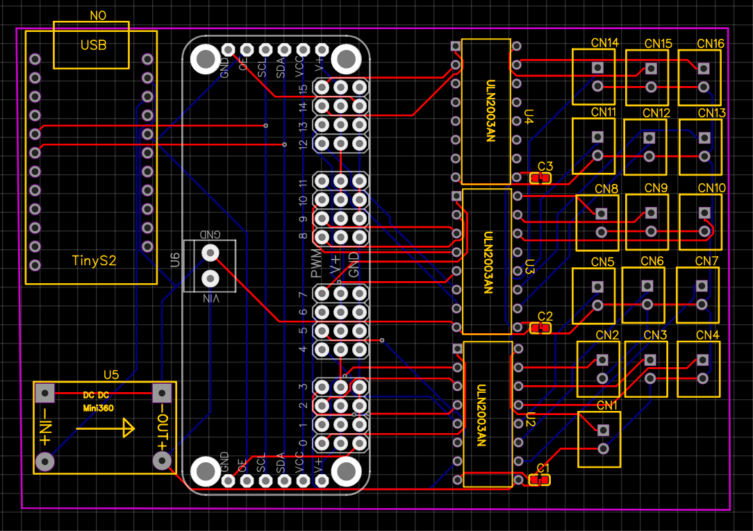
That went better than expected. I forgot this was a dual-layer board. I probably could have even moved them closer together.
But I should probably increase the track thickness for the tracks carrying high currents.
Given the 1.7 Amps, I'd say 0.75mm should be fine.
Then I'll just wire that to the TinyS2... oh huh.
I've added a barrel jack to power the board instead, I'll just plug in a 12V supply.
Here's the updated version:
Much better!
I'll go ahead and order a few of them. I've got plenty of parts here.

I did one last check of the workshop to make sure I've got everything. Due to my extensive hoard... uh preparedness I have everything needed. They can just use whatever generic they want for the SMD capacitor.

One last design check!
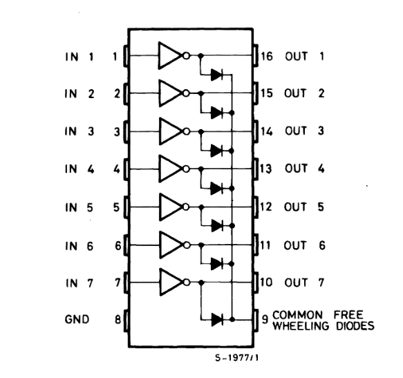
Hang on, is that actually how the ULN2003A works? I thought pin 9 was the flyback common.
Oh... I was using the module pinout, but I only have DIP chips.
What I want is something like this:

Shit.
....

The design is now fixed, but maybe not my sanity.

Hopefully, that'll be the end of it.
I went ahead and ordered the board to my workplace with the same settings as before.
Alright, well that might be a week and a half.
Discussions
Become a Hackaday.io Member
Create an account to leave a comment. Already have an account? Log In.