 BaumInventions
This is just a little writeup i can link to if i need to explain the tools for any CAN BUS Project i work on.
I am pretty sure the tools i use are not the best, cheapest, most expensive, well known or anything else ... They are just the things that have worked best for me over the years.
Back in 2012 when i started playing with CAN-BUS the choice of reasonable priced tools available to me was quite thin... Also my knowledge was quite thin too :) ...
I was not sure if i do things right. A lot of experiments with Can Shields and random Car hardware from the Scrapyard (and my car) led to non satisfying results in even reading can bus. I didnt know about Baudrates, or termination resistors... For the beginning i just wanted a out of the box experience that already does the things i want. I just wanted 1 layer less stress. So i bought the most expensive tool i ever bought.
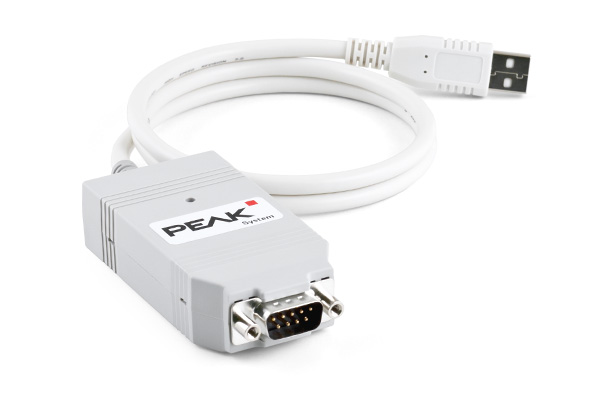
A PEAK Pcan USB ... As you can see it is about 190 Euros... THAT is very expensive for me BUT in the world of professional Industrial grade CAN Hardware that is nothing...
Now 10 years later i can say: That was one of the best investments i have ever done...
I KNEW that the Pcan will work right because it is a real professional tool from a well known brand. PEAK let you download the full API to write your own apps to use the Pcan Interface... BUT i am just using Pcan View example software to recieve and send can messages. The program is super simple and FAST!
It is really important to listen to ALL messages on the CAN BUS. If you have slow hardware you can miss messages.
Today there are several open source and commercial can sniffing tools. I know they exist. I always wanted to try some but Pcan always worked so incredibly well.
This is why i use a super specific and expensive Tool... Not because its the best currently available... Because at the time it was the best solution for ME. And it never even once let me down.
Now that i had sorted out the most expensive part and could start to hack, i instantly fell back into my old habit of just buying the cheapest stuff i can get my hands on :) .
Some experiments later i discovered the world of cheap chinese can Boards called "MCP2515". Thats simply the name of the specific Chip they use... Sometimes they are called "TJA1050" wich is the other chip on the board.

The Datasheet or the inner workings are not really important to understand thanks to an awesome Library:
At the time these were quite new and only a hand full of libraries existed to use them with Arduino.
One of the libraries that worked for me is the "MCP_CAN_lib" . You can see it is quite old now. But it still gets updates! This is why i use this library... It worked for me from back then till today. A great piece of code.
The setup of the library is quite simple if you know the can bus baudrate you want to connect to. It is fast enough to properly communicate... even with my super messy amateur code!
But small things first: Connect the CAN BUS.
CAN is just 2 wires. Its a differential pair, wich means that one wire always has the opposite state as the other one. If one is powered the other one is off. Simple. CAN wires are normally twisted around each other to cancel out magnetic fields. And thats quite important to make it work...
The two wires are called CAN H(igh) and CAN L(ow). If you connect them the wrong way around nothing bad happenes or breaks... it simply doesnt work. In Car applications the used components are normally quite good and create a proper network to simply tap into without any problems.
There are different ways to connect can devices together. Its called "topology". I found a "star" topology in cars like Renault Clio, Dacia Dokker or Dacia Logan. Megane 3 for example uses combinations of "line" and "star" topology.
If you just want to get things working the topology isnt that important. Most of the devices in a "line" topology simply send messages through themselfes if a message must be sent from one end of the chain to the other end.
If you connect just to a single CAN enbaled device (or a part of a network that doesnt work) its possible that MCP or Pcan are not abled to establish a proper connection and get the BUS going. Then there is probably no "termination"... Thats sounds worse then it is , because it is just a 120 OHM resistor in parallel to the CAN H and L lines. MCP´s jumper "J1" below the screw terminal boes exactly this. With Pcan i just use a 120 OHM resistor somewhere in parallel to the CAN lines.
Now the connection should be good.
Lets talk about how i set up a sniffing session with the Pcan. If you get a different solution it should at least have some similar settings and workflow. It is the bare minimum.
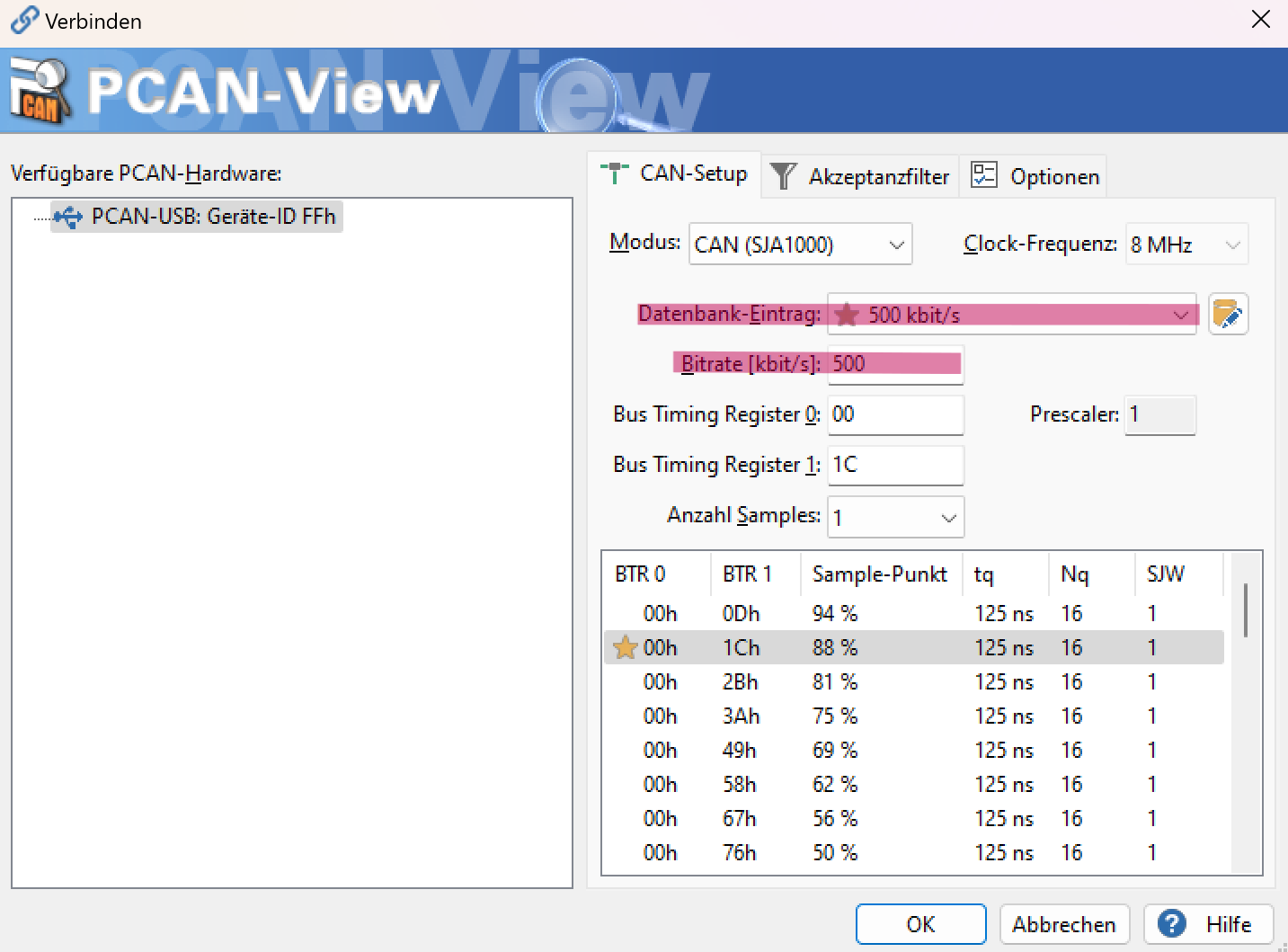
This is the first screen when i connect the interface to the software. The only really importent part i have marked red.
Here you can set the Baudrate of the CAN BUS. Thats the speed of the BUS. In most cases it is something like 500 or 250kbit/s. Pcan could be set up from 5kbit/s to 1Mbit/s but to be fair everything i have ever used is 500kbit/s. The Clock-Frequency is always 8MHz and is not changable here... so we just ignore it.
Another useful setting is the Filter. If you are just interested in messages out of a specific range you can set this up here.
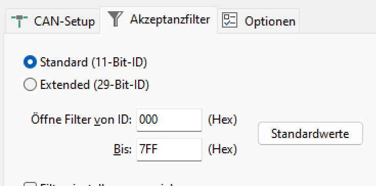
The range of adresses in 11Bit ID Format is from 0x000 to 0x7FF (HEX). Thats the mode most cars will use.
BTW. It is pretty useful to learn how HEXadecimal works... In short we dont count from 0 to 9 ... we count from 0 to F based on 4 BITS (where 8 BITS combine into 1 BYTE). HEX is the base of CAN. To properly understand and handle CAN you really have to understand HEX.
I am not a programmer... just a dude that has tought himself the stuff to understand what is needed to make it work. If i can do this you can do it too. It took me literally years to get to the point where i am now. I bet you can do this faster!
If you have set the baudrate right (and connected everything correct) you should get consistent Data.
Wich should look like this :
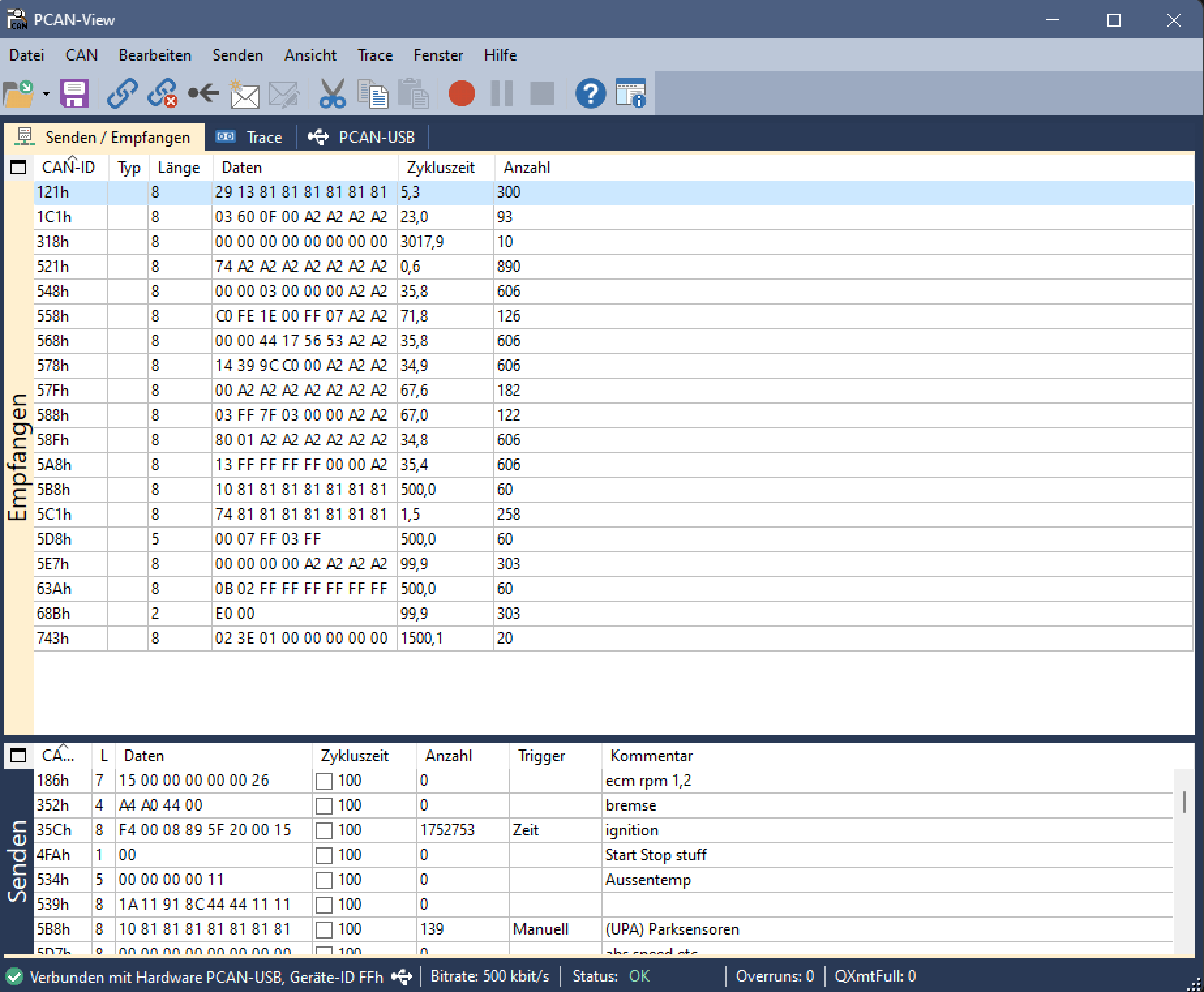
In the upper BOX you can see the Data that is currenty sent on the connected CAN. In the Lower Box there are some Messages i have set up to send as tests.
The CAN-ID is the address of the message. The IDs are fixed to the devices that send them. It will never chage.
Another not that unimportant information is the cycle time. Some messages are just sent on request, but most of them are sent periodically.
The most important bit is the data. Here we can see what these small black boxes are actually talking.
Up until here the preperation is the same for every can Project. The real fun starts here. Because:
Each car manufacturer does its own thing with the Data. One Bit or Byte most likely will not do the same thing on a VW Radio and a Renault Radio. Not even for example the CAN Bus of a Renault Clio is fully compatible with a Renault Megane.
But sometimes the manufacturers are forced to work together to make standards. Thats a good thing!
And sometimes the manufactueres even use these standards. Thats an even better thing!
One of these standards is "ISO-TP" in short. A Protocol used to transmit Data. I found this protocol several times implemented in the real world. So i think its important to at least know about it so you can identify it if you see it.
Now you know the basics of my workflow. If you have questions please feel free to ask.
Each Can Project of me will use these tools and this workflow to get it going. Specific settings and/or code will be contained in each Project.
Thanks for reading my Ted Talk.
Discussions
Become a Hackaday.io Member
Create an account to leave a comment. Already have an account? Log In.