 teardownit
The interpretation of the measurement results should be discussed in particular. What should be done after the cable fault location has been searched and the distance to the defect has been measured? First, it is necessary to find the scheme where the cable route is indicated and to estimate approximately which section of the cable the localized defect is located. It is required to make clarifying measurements from the switching points closer to the defect. Other measuring devices, e.g., TDR, should verify the results. Then it is necessary to measure a known distance to the defect on the cable route. It is most convenient to use measuring wheels for this purpose. However, the cable is not laid strictly along the line, so the defect may be quite far away from the postponed point. That is why before searching for the place with a defect on the cable, it is necessary to find the closest switching point to it and measure the defect from it.
Another group of "secrets" is related to the defect localization on real cables, which always consists of several sections. The section parameters may differ, e.g., regarding cross-section (which affects DC measurements) or cable type (which affects AC measurements). This is another reason you should measure as close as possible to the fault to be detected.
For composite cables
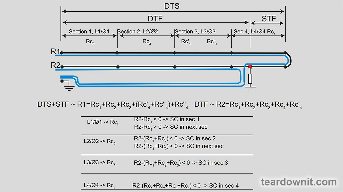
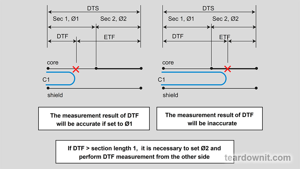
The rules to be followed when performing measurements on composite cables and DC are simple (see the following two figures). In cases where the faults to be localized are caused by low insulation resistance of the conductors (short circuits of the conductors to the shield or to each other). The same rules apply to AC measurements when localizing faults caused by increased core resistance (breaks).
For cable branches
A separate case is the fault localization in cables with taps. The general rule to avoid errors is that measurements should be carried out on individual cable segments. In cases where this is impossible, they are carried out on the cable with branches. But always keep in mind that the result depends on the choice of the location of the strap. Suppose the measurements indicate that the defect is located at the switching point. In that case, it may also mean that the branch cable is connected to the cable where the defect is located. It can be localized by disconnecting the branch, taking measurements, or changing the strap position.
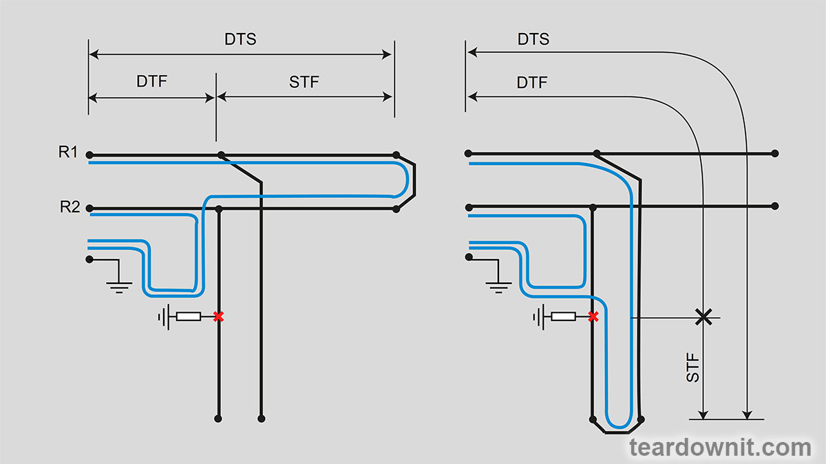
The figure above shows that if there is a defect in an undocumented tap, the fault location may be misleading - it will look like the problem is at the tap connection point. And the measurements on both sides will give the same result. In such a case, only an OTDR, where the tap will be visible, or cable examination at the switching point will help to finally determine the location of the defect.
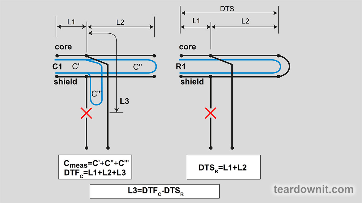
When an AC measurement is used to locate a wire break, the presence of an undocumented tap will also lead to erroneous results, but in a much less predictable manner. If the tap is located upstream of the open circuit, it will introduce an unknown added capacitance. The actual distance will therefore be less than the measured distance.
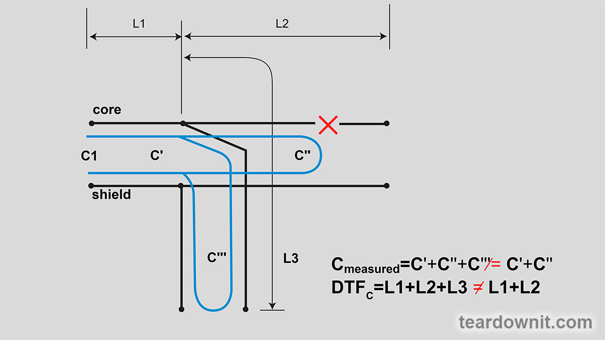
When localizing a break on a line with taps, it is also necessary to make two measurements according to the diagram shown in the figure below. One measurement is made with an AC bridge, and the other with a DC bridge.
Of course, these rules can only be followed if there is documentation of the cable network where the defect is localized. Therefore, when the first serious fault is eliminated, carefully prepared documentation will more than compensate for the time and resources spent on its creation.
Accepted designations
In most cable fault locators, the following intuitive and convenient symbols are used to designate the lengths of the various cable sections with localizable faults, which were chosen for the figures in this article:
DTS = Distance To Strap (distance from the device connection point to the installation point of the jumper at the far end);
DTF = Distance To Fault (distance from the device connection point to the pair fault);
STF = Strap To Fault (distance from the damage point to the place of installation of the jumper at the far end of the pair);
DTE = Distance To End (distance from the device connection point to the twisted pair end);
ETF = End To Fault (distance from the fault location to the end of the cable line farthest from the device).
Discussions
Become a Hackaday.io Member
Create an account to leave a comment. Already have an account? Log In.