 simeononsecurity
Table of Contents
- Introduction
- Step-by-Step Setup
- Alternatively, copy the firmware files to the extracted esptool.exe’s folder and run the following as an administrator
- Additional Configuration For Unicorecomm UM980 and UM982 Devices
Best Budget DIY GPS/GNSS Base Station using the UM980 and a ESP32
Introduction
The ESP32 is a versatile microcontroller renowned for its WiFi and Bluetooth capabilities. In this guide, we’ll walk you through setting up the your ESP32 development board with the Unicorecomm UM980 and various accessories. We’ll also cover flashing the ESP32 with the desired firmware.
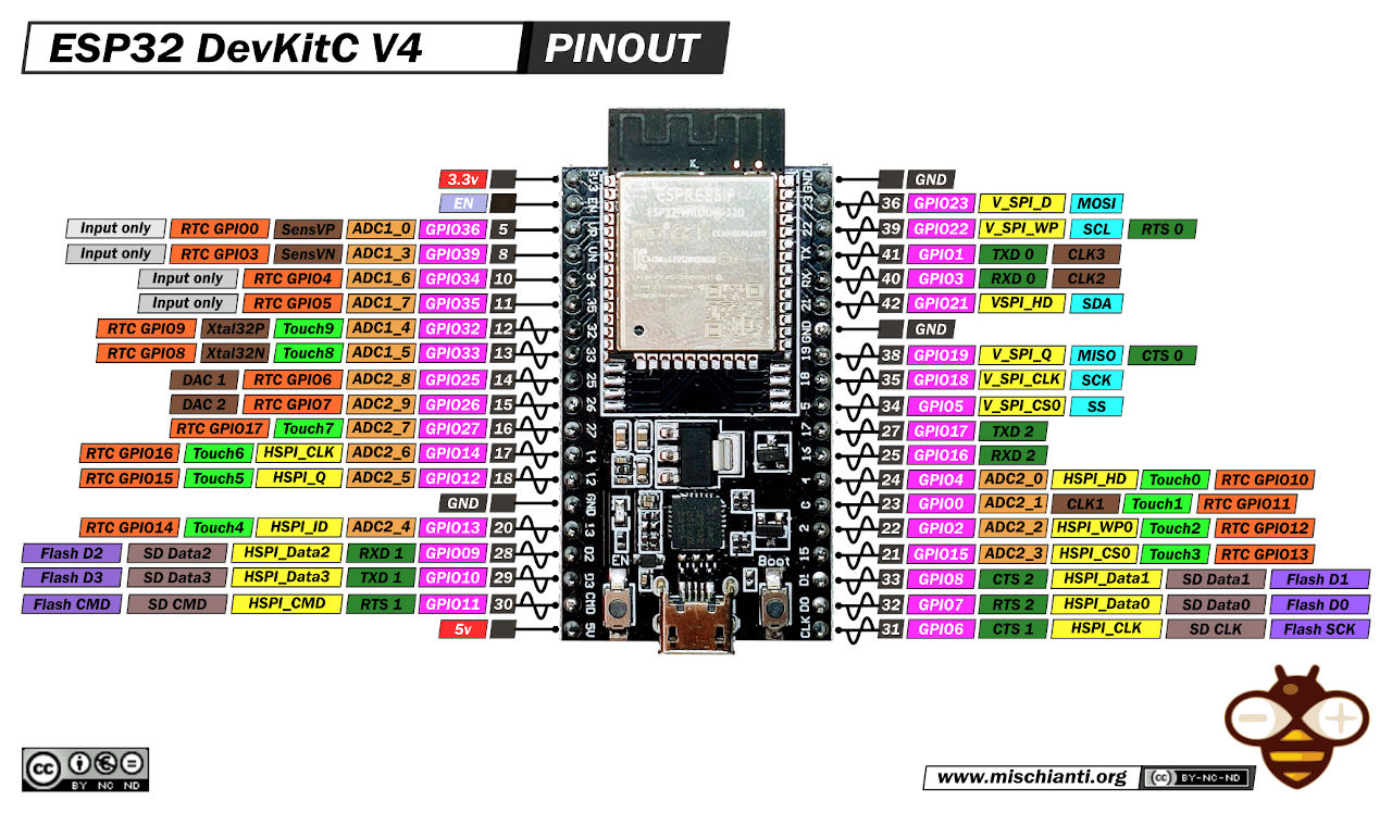
ESP32 Wroom DevKit Full Pinout - mischianti.org
Alternate Instructions
Want to use a linux distro or a raspberry pi?
Check out our guide on Setting up a NTRIP server on Linux
Looking for how to use this with Onocoy?
Check out our guide on DIY Onocoy Ntrip Server and Reference Station Setup
Hardware Components
Before we begin, let’s take a look at the hardware components you’ll need:
ESP32 Development Board: AITRIP 2 Sets ESP-WROOM-32 ESP32
Power Supply: CanaKit 3.5A Raspberry Pi 4 Power Supply (USB-C)
Adapter Cables: (Choose one):
- elechawk 9 PCS 1.25mm to Dupont 2.54mm Pitch Adapter Cables
- PB1.25 to Dupont 2.54mm Connectors and Cables Kit Compatible with Molex PicoBlade 1.25mm Pitch Connectors 20cm Wires
- 2Pcs 1.25mm to 2.54mm dupont cable 1pin female 2.54mm wire connector 1.25mm 2/3/4/5/6P wire harness 28AWG Length 20cm - Choose the 4P Option
Enclosure Kit: qBoxMini DIY IOT Enclosure Plus Kit (One SMA)
GNSS Receiver Board (Choose one):
- UM980 RTK InCase PIN GNSS receiver board with USB C
- Use discount code
SIMEONSECURITY_GNSSfor an additional 5% discount. - If you choose this option, you’ll need some male to male dupont wires .
- Use discount code
- Full Frequency Centimeter Level Low-power and High-precision UM980 Module RTK Differential Drone GPS Module GNSS Whole System
- UM980 RTK InCase PIN GNSS receiver board with USB C
Firmware: ESP32-XBee Firmware
Recommended Antennas
Basic Antennas for RTK, ROVER, Window Situations
- Bingfu GPS Navigation Antenna
- $9
- Basic, simple, not the best, but it works.
- Bingfu GPS Navigation External Antenna
- $24
- Outdoor Rated, Cheap, Allows view of the Sky.
- SparkFun GNSS-RTK Accessory Kit
- $85
- This is only recommended for those who can not properly install the antennas below. It will underperform against the others.
Advanced Antennas for Base and Reciver Stations
- (Preferred)
Beitian High Gain High Precision GPS/GNSS Antenna
- $86
- High Antenna Gain, High Precision, Builtin Anti-interference, IP67 Rated, High and Low Temp Ratings, UV Resistant Housing, Supports Most Bands..
- (Preferred)
Calibrated Survey GNSS Tripleband + L-band antenna (IP67)
- $230
- Calibrated Quad-Band, Extremely High Precision, Anti-interference, Supports All Bands
- Multi-frequency High Precision Survey Antenna
- $95
- Strong Antenna Signal, High Precision, Builtin Anti-interference.
- GNSS Surveying Antenna and Precise Navigation Antenna
- $180
- High Antenna Gain, Extremely High Precision, IP67 Rated.
- HARXON CSX627A
- $135
- Calibrated Triple Band RTK Antenna, IP67, Supports All Bands
- L1/L2/L5 GPS, G1/G2/G3 GLONASS, B1/B2/B3 BDS, Galileo E1/E5/E6 38dB Antenna
- $205
- Supports Most Bands, IP67 Rated
Step-by-Step Setup
1. Assemble Your Workstation / Desktop / Laptop
Ensure you have a computer with a USB port and internet access. You’ll need this for downloading firmware and drivers.
2. Connect Hardware Components
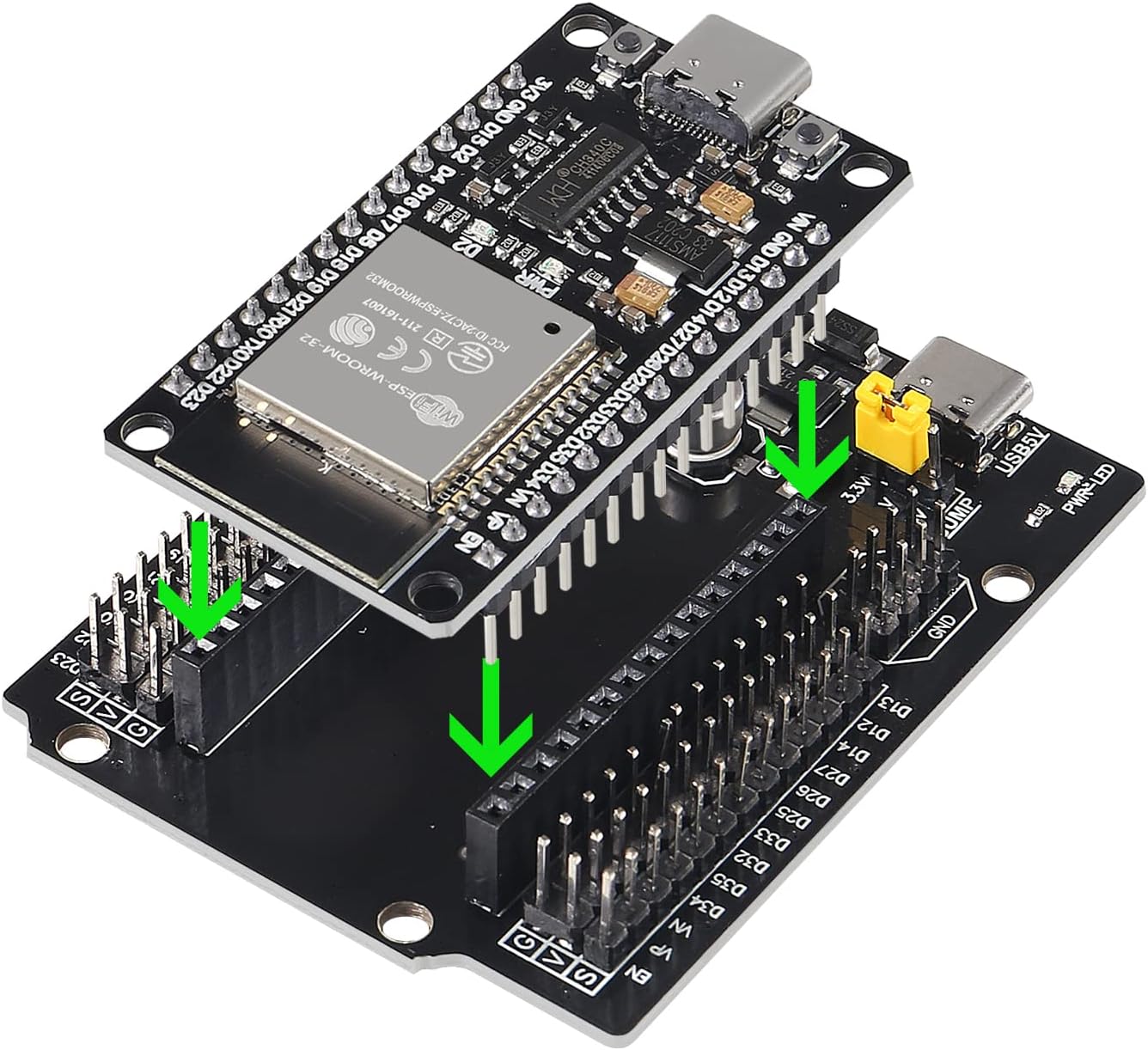
- If applicable, plug the ESP32 into the breakout board.
![Connecting ESP32 to Dev Board]()
ESP32 Dev Board
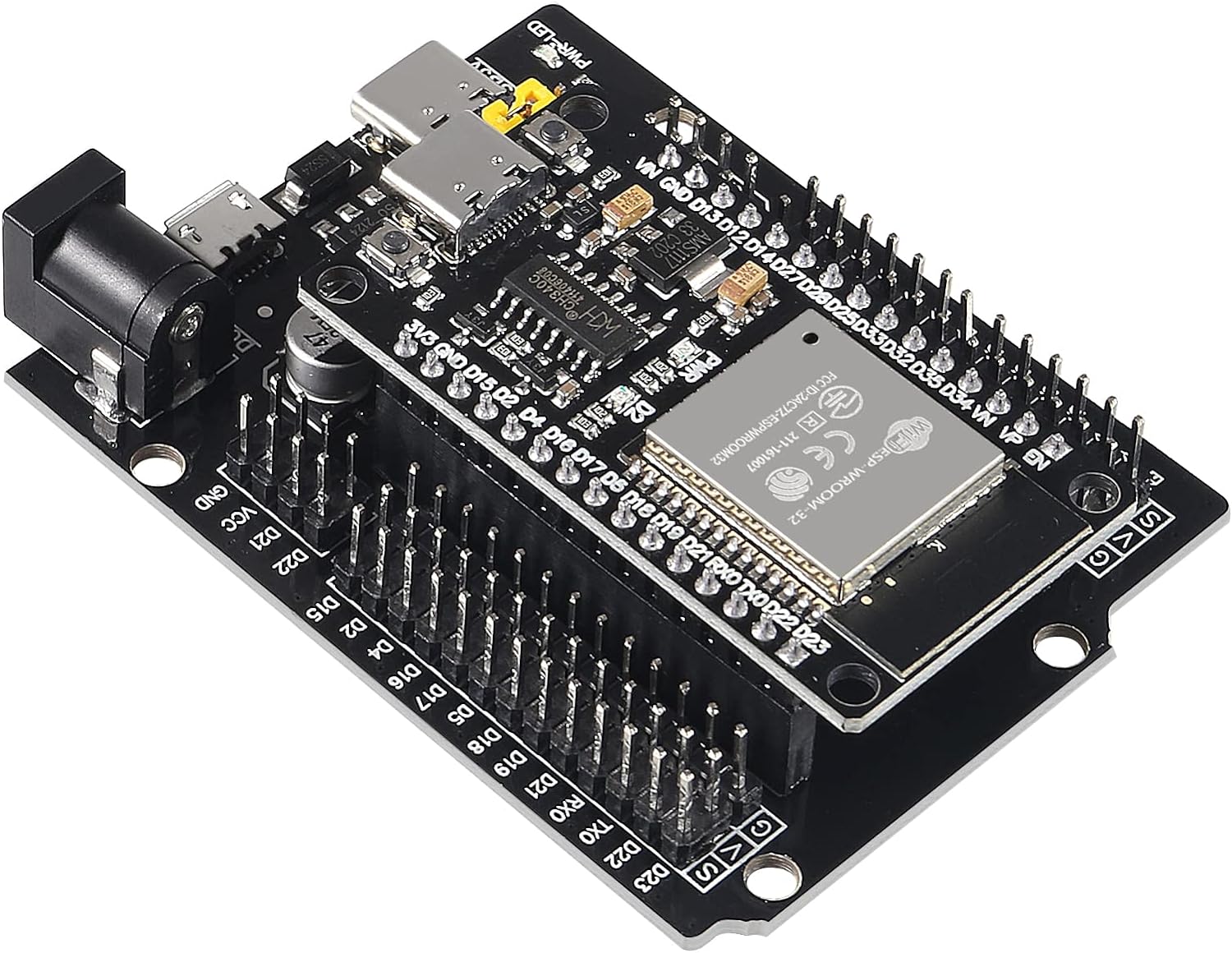
![ESP32 Dev Board]()
ESP32 Dev Board
- Connect the ESP32 development board to your computer using a Type-C USB cable .
3. Use Adapter Cables
Utilize the elechawk adapter cables or alternatives as necessary to connect the UM980 to your ESP32 board . These cables offer compatibility with various connectors for expanding your project.
- UM980 RTK InCase PIN GNSS receiver board with USB C
- If you choose this option, again, you’ll need some male to male dupont wires
- Wiring
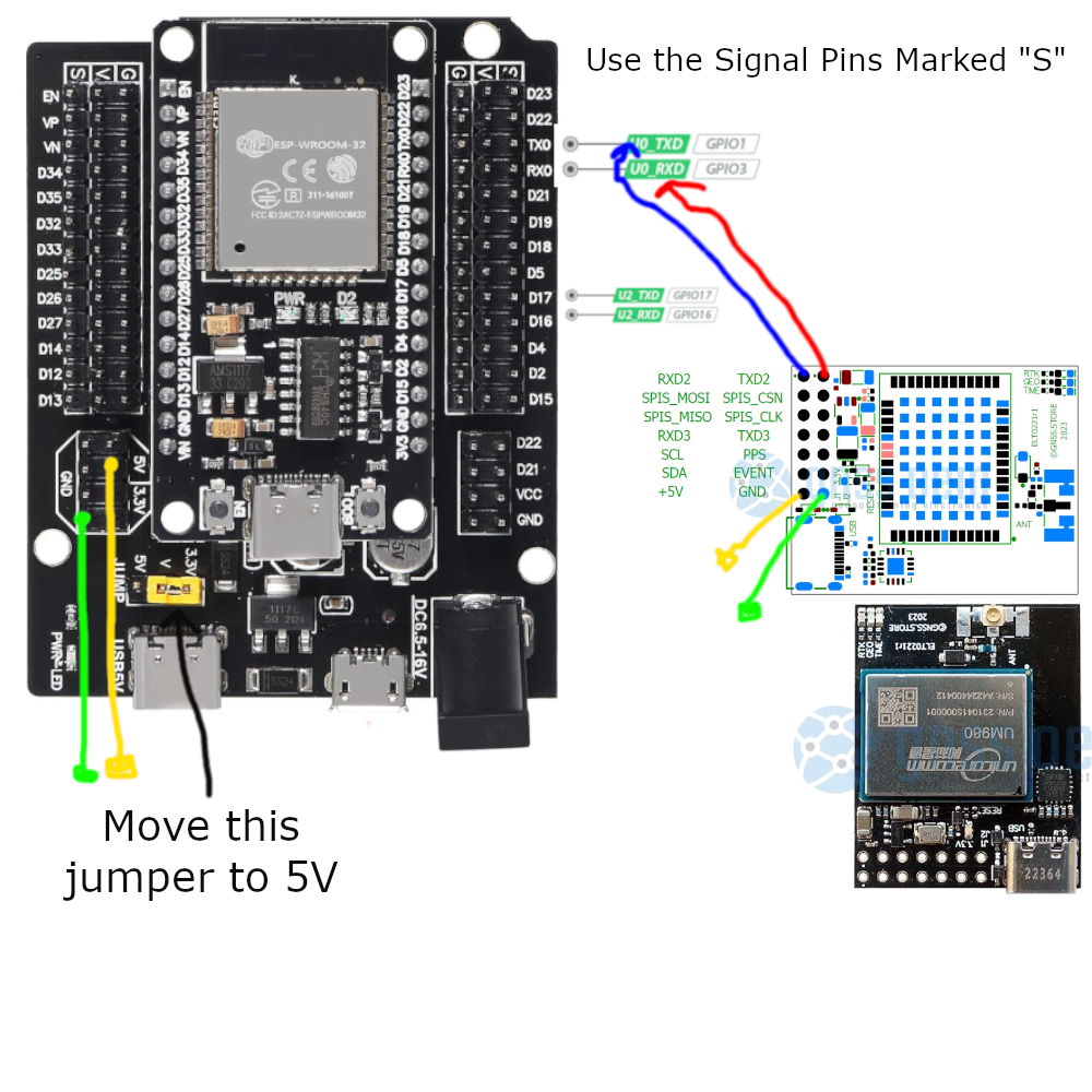
UM980 +5VtoESP32 5V(or 3V3) for power.UM980 GNDtoESP32 GNDfor ground.UM980 TXD2toESP32 GPIO pindesignated for receiving data (e.g.,GPIO pin 16,RX1,RX0).UM980 RXD2toESP32 GPIO pindesignated for transmitting data (e.g.,GPIO pin 17,TX1,TX0).![Connecting the GNSS.store UM980 Module to The ESP32 Devboard]()
GNSS.store UM980 to ESP32 Dev Board Breakout Pin Diagram
- Full Frequency Centimeter Level Low-power and High-precision UM980 Module RTK Differential Drone GPS Module GNSS Whole System
- Wiring
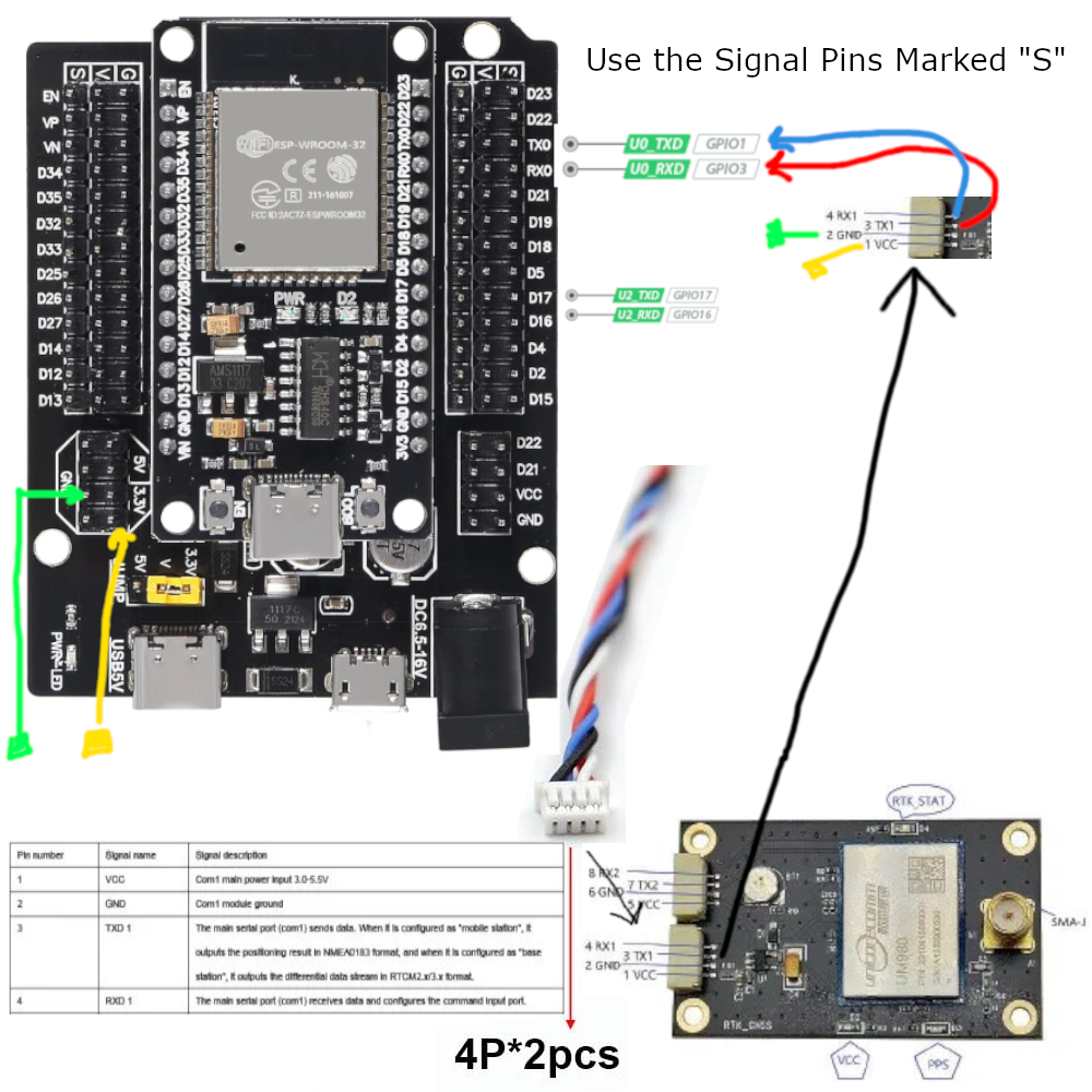
UM980 UART VCC (Pin 1)toESP32 3.3V(or 3V3) for power.UM980 UART GND (Pin 2)toESP32 GNDfor ground.UM980 UART TXD (Pin 3)toESP32 GPIO pindesignated for receiving data (e.g.,GPIO pin 16,RX1,RX0).UM980 UART RXD (Pin 4)toESP32 GPIO pindesignated for transmitting data (e.g.,GPIO pin 17,TX1,TX0).![Connecting the AliExpress UM980 Module to The ESP32 Devboard]()
AliExpress UM980 to ESP32 Dev Board Breakout Pin Diagram
- Wiring
4. Employ the Enclosure Kit
For environmental protection, consider using the qBoxMini DIY IOT Enclosure Kit . It offers waterproof protection and includes connectors and a prototyping PCB for easy integration.
5. Choose the GNSS Receiver
Depending on your project needs, timeline, and budget, select the appropriate GNSS receiver board . Follow the wiring diagram above for implementation.
6. Flash the Firmware
To flash the ESP32 with the ESP32-XBee firmware , follow these steps:
- Download the firmware from the provided GitHub release .
Go to the latest stable firmware release and download:
bootloader.binpartition-table.binesp32-xbee.binwww.bin
If you would like to reset the device configuration, you should also download:
- `wipe_config.bin`
- Install necessary flashing tools like the ESP-IDF framework and Espressif’s ESP Flash Download Tool.
- Windows
- Windows Flash Tools from Espressif
- Linux
If you have not already done so, install the ESP flashing tool,
esptool:Ubuntu/Debian:
sudo apt-get install esptoolArch:
sudo pacman -S esptool
- Connect the ESP32 to your computer.
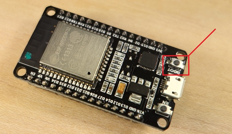
- While plugging into your computer, hold down the
BOOTbutton to prepare the ESP32 for Flashing.![ESP32 Boot Button]()
ESP32 Boot Button - randomnerdtutorials.com
- While plugging into your computer, hold down the
- Flash the XBEE ESP32 Firmware Note: Your COM device location will be different than mine. You’ll need to identify it first before continuing.
- Windows
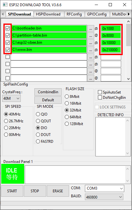
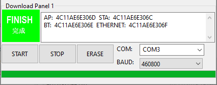
- Open
the ESP Flash Download Tool, select the firmware files, set flashing
options, and click “Start” to flash the firmware onto the ESP32.
![loading ESP32 Firmware on Windows]()
Loading ESP32 Firmware on Windows - github.com/nebkat/esp32-xbee/
- It is important that the offsets exactly match the files:
bootloader.bin@0x1000partition-table.bin@0x8000esp32-xbee.bin@0x10000www.bin@0x210000
- If you would like to reset the device configuration, you should also include:
wipe_config.bin@0x0
![Flashing ESP32 Firmware on Windows]()
Flashing ESP32 Firmware on Windows - github.com/nebkat/esp32-xbee/
Alternatively, copy the firmware files to the extracted esptool.exe’s folder and run the following as an administrator
.\esptool.exe --before default_reset --after hard_reset --chip esp32 --port COM10 --baud 115200 write_flash --flash_mode dio --flash_size detect --flash_freq 40m -z 0x1000 ./bootloader.bin 0x8000 ./partition-table.bin 0x10000 ./esp32-xbee.bin 0x210000 ./www.bin
- Open
the ESP Flash Download Tool, select the firmware files, set flashing
options, and click “Start” to flash the firmware onto the ESP32.
- Linux
esptool.py -b 460800 --after hard_reset write_flash --flash_mode dio --flash_freq 40m --flash_size 4MB 0x8000 partition-table.bin 0x1000 bootloader.bin 0x10000 esp32-xbee.bin 0x210000 www.bin- If you would like to reset the device configuration, also include:
0x0 wipe_config.bin
Found 1 serial ports
Serial port /dev/ttyUSB0
Connecting....
Detecting chip type... ESP32
Chip is ESP32D0WDQ5 (revision 1)
Features: WiFi, BT, Dual Core, 240MHz, VRef calibration in efuse, Coding Scheme None
Crystal is 40MHz
MAC: 4c:11:ae:6e:30:6c
Uploading stub...
Running stub...
Stub running...
Configuring flash size...
Compressed 3072 bytes to 110...
Wrote 3072 bytes (110 compressed) at 0x00008000 in 0.0 seconds (effective 1540.7 kbit/s)...
Hash of data verified.
Compressed 17216 bytes to 11168...
Wrote 17216 bytes (11168 compressed) at 0x00001000 in 1.0 seconds (effective 138.8 kbit/s)...
Hash of data verified.
Compressed 788768 bytes to 493546...
Wrote 788768 bytes (493546 compressed) at 0x00010000 in 43.9 seconds (effective 143.8 kbit/s)...
Hash of data verified.
Compressed 1048576 bytes to 93902...
Wrote 1048576 bytes (93902 compressed) at 0x00210000 in 8.4 seconds (effective 1004.1 kbit/s)...
Hash of data verified.

Leaving...
Hard resetting via RTS pin...
- Restart the ESP32
- Hit the “EN” button
- Or Power Cycle the Device
7. Configuration
Step 1: Connect to the XBee Hotspot
- Using your phone or PC, connect to the ESP32’s WiFi Hotspot which will be called
ESP_XBee_XXXXXXwhereXXXXXXare some random numbers/letters unique to your device.
- Using your phone or PC, connect to the ESP32’s WiFi Hotspot which will be called
Step 2: Browse to the Configuration Page
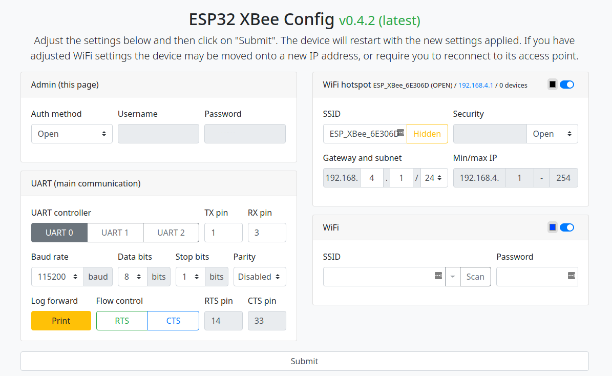
- Open your browser and navigate to http://192.168.4.1/. You should see a page similar to:
![XBee ESP32 Configuration Page]()
XBee ESP32 Configuration Page - github.com/nebkat/esp32-xbee/
- Open your browser and navigate to http://192.168.4.1/. You should see a page similar to:
Step 3: Configure WiFi
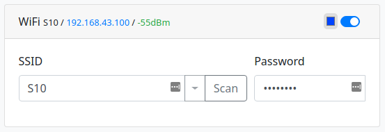
Enable the WiFi section, press Scan to search for networks, choose your home WiFi network (or phone hotspot) and enter the password.
The ESP32 does not have very good WiFi reception, so make sure you are relatively close to the network you are connecting to, especially when indoors, to avoid problems.
Press the Submit button, and follow the instructions on screen. You may need to reconnect to the ESP32 XBee hotspot after it restarts.
The WiFi section will now show its connection status:
![XBee ESP32 Wifi Configuration Page]()
XBee ESP32 Wifi Configuration Page - github.com/nebkat/esp32-xbee/
If you are connected to the device using a serial terminal, the device will output information about its WiFi connection.
$PESP,WIFI,STA,CONNECTING,S10,P*71
$PESP,WIFI,STA,CONNECTED,S10*4C
$PESP,WIFI,STA,IP,192.168.43.100/24,192.168.43.1*5D
Step 4: Improve Security Configuration
Hotspot
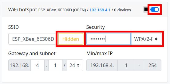
To prevent others from accessing your ESP32 XBee, you may want to adjust the settings of the WiFi hotspot section.
There are three ways to do this:
- Change from Open security to WPA/2-PSK and enter a password (recommended).
- Hide the SSID by toggling the Hidden setting.
- Note: This will not prevent connections, but will hide the hotspot from WiFi scans on other devices.
- Disable the hotspot entirely by toggling the WiFi hotspot section
- Note: You will not be able to access the ESP32 XBee if there is a problem with its connection to your home WiFi network, unless you perform a Full Reset .
![XBee ESP32 Secure Wifi Configuration Page]()
XBee ESP32 Secure Wifi Configuration Page - github.com/nebkat/esp32-xbee/
Configuration
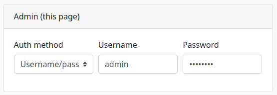
If you would like to prevent others on your home network from modifying the ESP32 XBee configuration, you can also adjust the settings of the Admin section.
You can choose between only allowing devices connected to the hotspot, or a username/password.
The new IP address will be the first address in the 3rd line as above, i.e. 192.168.43.100.
![XBee ESP32 Admin User Configuration Page]()
XBee ESP32 Admin User Configuration Page - github.com/nebkat/esp32-xbee/
Step 5: Improve Security Configuration
You can now proceed to configure the available protocols.
Note: Do not enable all protocols at once. The ESP32 is not able to handle an unlimited amount of open sockets/connections, so only enable the protocols you are actually using.
The small color selector beside each section’s toggle button will determine the color of the RGB LED on the ESP32 XBee for that feature, so that you can keep track of its status. Setting the color to black will disable the LED for that feature. Typically, a fading LED means the feature is working correctly/connected, while a blinking LED or no LED means the feature is awaiting a connection or could not connect to its target.
7. Profit?
8. Extras
Full Reset: In case you encounter any problems and are unable to connect to the device, simply hold the
BOOTbutton for 5 seconds, and the ESP32 will be reset to its default configuration.![ESP32 Boot Button]()
ESP32 Boot Button - randomnerdtutorials.com
If this procedure does not work for any reason, an alternative method to perform a full reset is to follow the Firmware Update procedure, including the
wipe_config.binfile as described.
Additional Configuration For Unicorecomm UM980 and UM982 Devices
To enable all the bands and base station mode on the Unicorecomm devices you’ll need to serial into them using baud rate of 115200 and run the following commands. This can be done within terminal, putty, or the
Unicorecomm UPrecise
software.
mode base time 60 2 2.5: This line configures the reference station’s operation mode, which is set to “base”. In this configuration the base station will figure out it’s actual location after receiving traffic for 60 seconds.CONFIG SIGNALGROUP 2: This command appears to configure the signal group for the UM980/UM982 devices. This enables all bands and frequencies on the device.rtcm1005 30 and rtcm1006 30: These commands set the rate at which RTCM messages 1005 and 1006 are sent out from the reference station, respectively. The values “30” commands a 30-second interval.rtcm1033 1, rtcm1074 1, rtcm1077 1, rtcm1084 1, rtcm1087 1, rtcm1094 1, rtcm1097 1, and rtcm1117 1, rtcm1124 1 and rtcm1127 1: These commands enable RTCM messages, ensuring that the reference station transmits these specific messages. The value “1” enables these messages to happen every second..saveconfig: This command saves the configured settings, ensuring that they persist and are applied whenever the reference station is operational.
Unicorecomm UM980 and UM982 Configuration Script
mode base time 60 2 2.5

CONFIG SIGNALGROUP 2

rtcm1005 30
rtcm1006 30
rtcm1033 1
rtcm1074 1

rtcm1077 1
rtcm1084 1
rtcm1087 1
rtcm1094 1
rtcm1097 1
rtcm1117 1

rtcm1124 1
rtcm1127 1

saveconfig
*It should be noted that the Unicorecomm device does not have the ability to transmit the RTCM 1230 message type.
Unicorecomm UM980 and UM982 Commands Reference Manuals
For additional configuration guidance, consult the following documentation:
9. Testing
Once the firmware is successfully flashed, your ESP32 board is ready for testing. Begin developing and running IoT applications, making the most of the board’s WiFi, Bluetooth, and GNSS capabilities.
This is where you’ll unplug the ESP32 from your desktop and Plug the CanaKit Raspberry Pi 4 power supply into a power source and connect it to the ESP32 board via USB-C.
Testing is going to depend on multiple factors. This part is up to you. I suggest using Onocoy and using their service to test your configuration if you’re setting up an NTRIP Server.
Disclosure and Affiliate Statement:
Affiliate Disclosure: We may earn a commission from links on this page. These commissions support our website and the content we provide. Rest assured, we only recommend products/services we believe in. Thank you for your trust! Click Here to Learn More
Discussions
Become a Hackaday.io Member
Create an account to leave a comment. Already have an account? Log In.