 BastelBaus
- Multiple devices with the same I2C address?
- Don't like bit-banging?
- No money for extra I2C multiplexer?
- Spare IO ports ?
==> Continue reading !
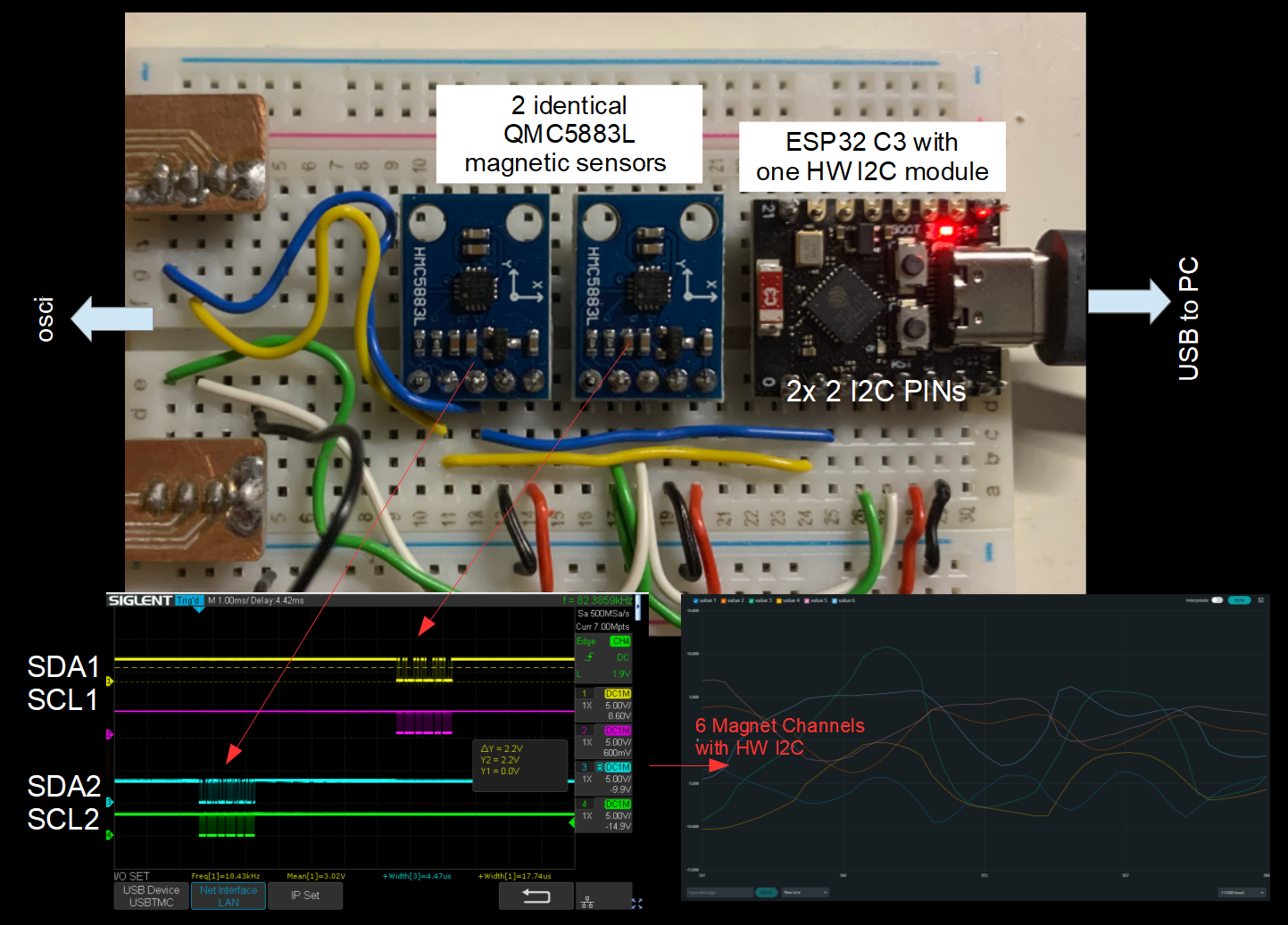
This was a short proof of concept to use the IO_MUX capability of the ESP32 to change online the PINs used for the I2C communication. Basically, the I2C hardware module can be connected to nearly every pin ofd the ESP32 and this switch can be done on the fly. I was not sure how good this work but a fast breadboard build and software sketch showed that it works like charme! See the picture and the code snippet below. Combining this with this nice hack to use only one SCL or SDA for multiple devices (link), this could be even more advantagous in several cases and save costs/space for an I2C multiplexer!
Picture of the breadboard setup:
The code snippet running on the ESP32:
// ESP32 S3 Dataseeht (as example) https://www.elecrow.com/download/product/DLC35010R/esp32-s3_datasheet_en.pdf
// Example i2c driver: https://github.com/espressif/esp-idf/blob/master/components/driver/i2c/i2c.c

#include <Wire.h>
#include "C:\Users\pagantroll\AppData\Local\Arduino15\packages\esp32\hardware\esp32\2.0.12\tools\sdk\esp32c3\include\driver\include\driver\i2c.h"
#include "C:\Users\pagantroll\AppData\Local\Arduino15\packages\esp32\hardware\esp32\2.0.12\tools\sdk\esp32\include\esp_rom\include\esp_rom_gpio.h"

#include <DFRobot_QMC5883.h>
DFRobot_QMC5883 compass(&Wire, QMC5883_ADDRESS );

#define I2C_SDA1 3
#define I2C_SCL1 4
#define I2C_SDA2 1
#define I2C_SCL2 2

void activate_I2C_GPIO_a() {
  i2c_set_pin(0, I2C_SDA1,I2C_SCL1, GPIO_PULLUP_ENABLE,GPIO_PULLUP_ENABLE,I2C_MODE_MASTER);
  esp_rom_gpio_connect_out_signal(I2C_SCL2, SIG_GPIO_OUT_IDX, false, false);
  esp_rom_gpio_connect_out_signal(I2C_SDA2, SIG_GPIO_OUT_IDX, false, false);
}

void activate_I2C_GPIO_b() {
  i2c_set_pin(0, I2C_SDA2,I2C_SCL2, GPIO_PULLUP_ENABLE,GPIO_PULLUP_ENABLE,I2C_MODE_MASTER);
  esp_rom_gpio_connect_out_signal(I2C_SCL1, SIG_GPIO_OUT_IDX, false, false);
  esp_rom_gpio_connect_out_signal(I2C_SDA1, SIG_GPIO_OUT_IDX, false, false);
}

void readMagSensor() {
  sVector_t mag = compass.readRaw();
  Serial.print(mag.XAxis);Serial.print(",");
  Serial.print(mag.YAxis);Serial.print(",");
  Serial.print(mag.ZAxis);Serial.print(",");
}


void setup() {

  Serial.begin(115200);
  Serial.println("Tesing I2C Multiplexing");

  Wire.begin(I2C_SDA1, I2C_SCL1);

  activate_I2C_GPIO_a();
  while (!compass.begin()) {
    Serial.println("Could not find a valid 5883 sensor on first port, check wiring!");
    delay(500);
  } Serial.println("First sensor initialized");

  activate_I2C_GPIO_b();
  while (!compass.begin()) {
    Serial.println("Could not find a valid 5883 sensor on second port, check wiring!");
    delay(500);
  } Serial.println("Second sensor initialized");

}


void loop() {
  delay(20);

  activate_I2C_GPIO_a();
  readMagSensor();

  activate_I2C_GPIO_b();
  readMagSensor();

  Serial.println("");
}
P.S.: Also thanks to the ESP forum (link) who gave me very fast advice!
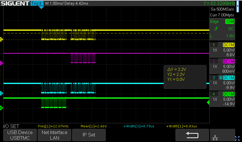
P.S.: Here the results with a common SCL line and only two seperate SDA lines. Works comparable nice :-)
Discussions
Become a Hackaday.io Member
Create an account to leave a comment. Already have an account? Log In.
I'm trying to do the same for an SPI slave. I have a device, an SPI master with just two lines (SCLK and MOSI) and I want my ESP32-S3 to sometimes listen to the first and sometimes to the second. I understand high-level what you do, but not enough to apply it myself to SPI slaving.
#define SPIIN_SCLK_B 35
#define SPIIN_MOSI_B 36
#define SPIIN_SCLK_A 37
#define SPIIN_MOSI_A 38
#define SPIIN_BUS FSPI
void spiin_for_A() {
spiAttachSCK(SPIIN_BUS, SPIIN_SCLK_A);
spiAttachMOSI(SPIIN_BUS, SPIIN_MOSI_A);
esp_rom_gpio_connect_out_signal(SPIIN_SCLK_B, SIG_GPIO_OUT_IDX, false, false);
esp_rom_gpio_connect_out_signal(SPIIN_MOSI_B, SIG_GPIO_OUT_IDX, false, false);
}
void spiin_for_B() {
spiAttachSCK(SPIIN_BUS, SPIIN_SCLK_B);
spiAttachMOSI(SPIIN_BUS, SPIIN_MOSI_B);
esp_rom_gpio_connect_out_signal(SPIIN_SCLK_A, SIG_GPIO_OUT_IDX, false, false);
esp_rom_gpio_connect_out_signal(SPIIN_MOSI_A, SIG_GPIO_OUT_IDX, false, false);
}
void spiin_init() {
spiin.setDataMode(SPI_MODE3);
spiin.begin(SPIIN_BUS, ... , ... , ... , ... ??? );
spiin_for_A()
... trigger A and read the messages it masters to us ...
spiin_for_B()
... trigger B and read the messages it masters to us ...
}
Any suggestions how to do this?
Are you sure? yes | no
Dear Maarten, SPI is designed to be a single Master mutliple slave setup. You can add additioonal devices by just adding a chip select line per new device and SCK/MISO/MOSI are wired to all devices. You might check out this tutorial for example: https://randomnerdtutorials.com/esp32-spi-communication-arduino/ (e.g. chapter "Multiple SPI Devices (same bus, different CS pin"). Hope this helps you
BR, BastelBaus
Are you sure? yes | no
Hi BastelBaus, thanks for the quick answer, but the communication is reversed to what you suggest.
The devices (A,B) I hook up to the ESP are SPI _masters_. In my system, the ESP triggers either A or B (forget it, but yes, the first free SPI block in the ESP is used for this), and after a while the triggered device starts mastering a message back to the ESP. I want to use the second SPI block in the ESP to receive from A (when A was triggered) or from B (when B was triggered).
Instead of having an external mux I wanted to used the pinmux internal to the ESP, just like you did :-)
Are you sure? yes | no
This should work for UART as well. The ESP32 has 3 UARTs, but if you are like me and need to speak to 5 modbus slaves over RS232, as well as 4 modbus slaves over RS485, as well as acting like a modbus slave over yet another RS485 bus, you start looking for ways to connect more!
So, just like you have done by reinitialising the I2C bus in between each read, do the same with a serial peripheral. Just substitute new RX and TX GPIO's when calling Serial.begin(), and you're golden! This should get you up to 10 or even more hardware-backed UARTs, so long as you can control who talks and when, and it is acceptable to have a little bit of latency between each conversation.
This obviously won't work when the remote end can talk at any moment. For that, you probably want to look at SoftwareSerial, bit-banging the serial protocol using interrupts and timers.
Are you sure? yes | no
brillant! thanks for this idea.
Are you sure? yes | no