 dittohead
Once in Internet I found photos of giant soviet panel named IGG1 (ИГГ1). It was looking stunning!
This panel made in two versions:
IGG1–32x32 with 32x32 dots resolution
IGG1–64x64 with 64x64 dots resolution
Some technical data:
Brighntness: 150–300 kd\m2;
Minimal anode voltage: 210–240v;
Working voltage: 400v
Working voltage range: 370–420v
Current per dot: 25 uA;
Refresh frequency: 1000 Hz;
Maximum cathode duty cycle: 64;
Anode duty cycle: 32;
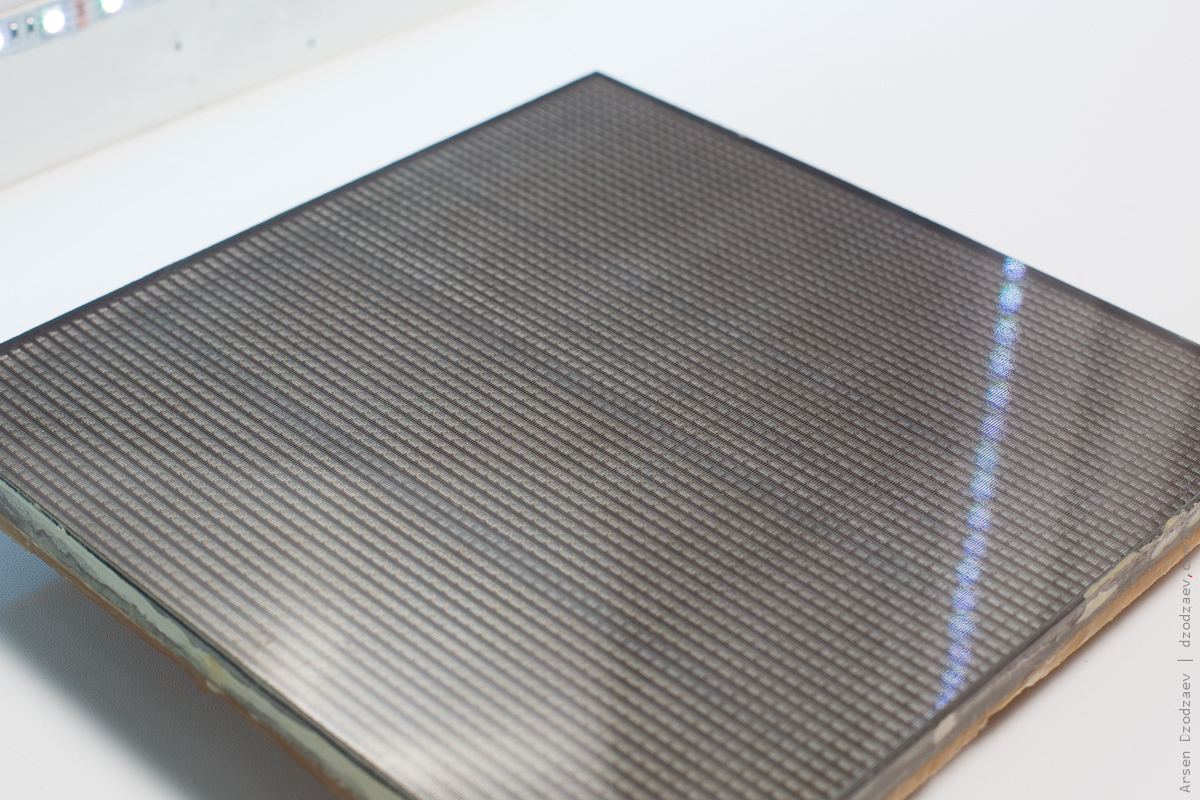
Dimensions: 193x193mm;
Weight: about 1 kilo.
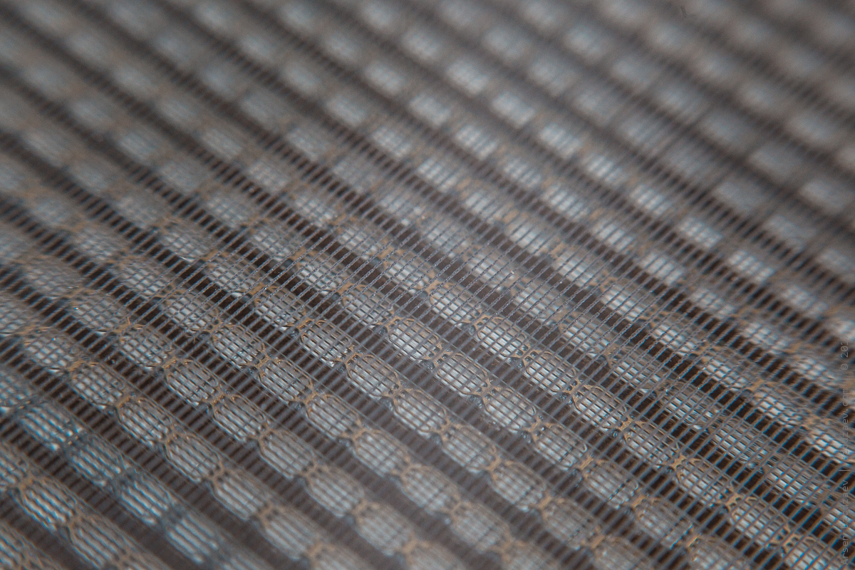
64 version have two alternates dots colors: green and orange
Made at late 1980x — beginning 1990x at “Gazotron” factory (Rivne, Ukraine)
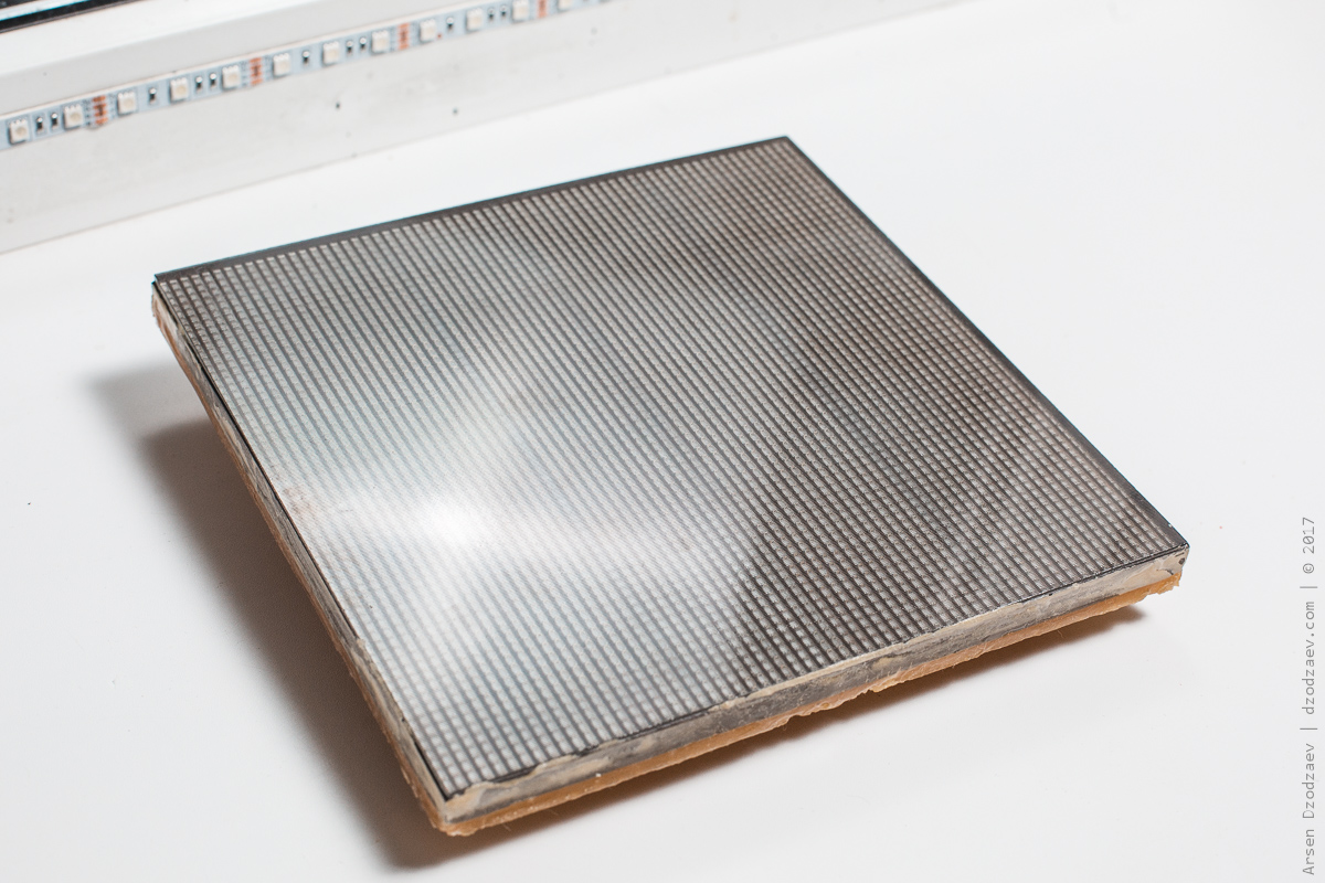
Today I got one IGG-64 for test. Maybe do some table clock with Wi-Fi sync:)
On photos it looks more smaller than in real life.
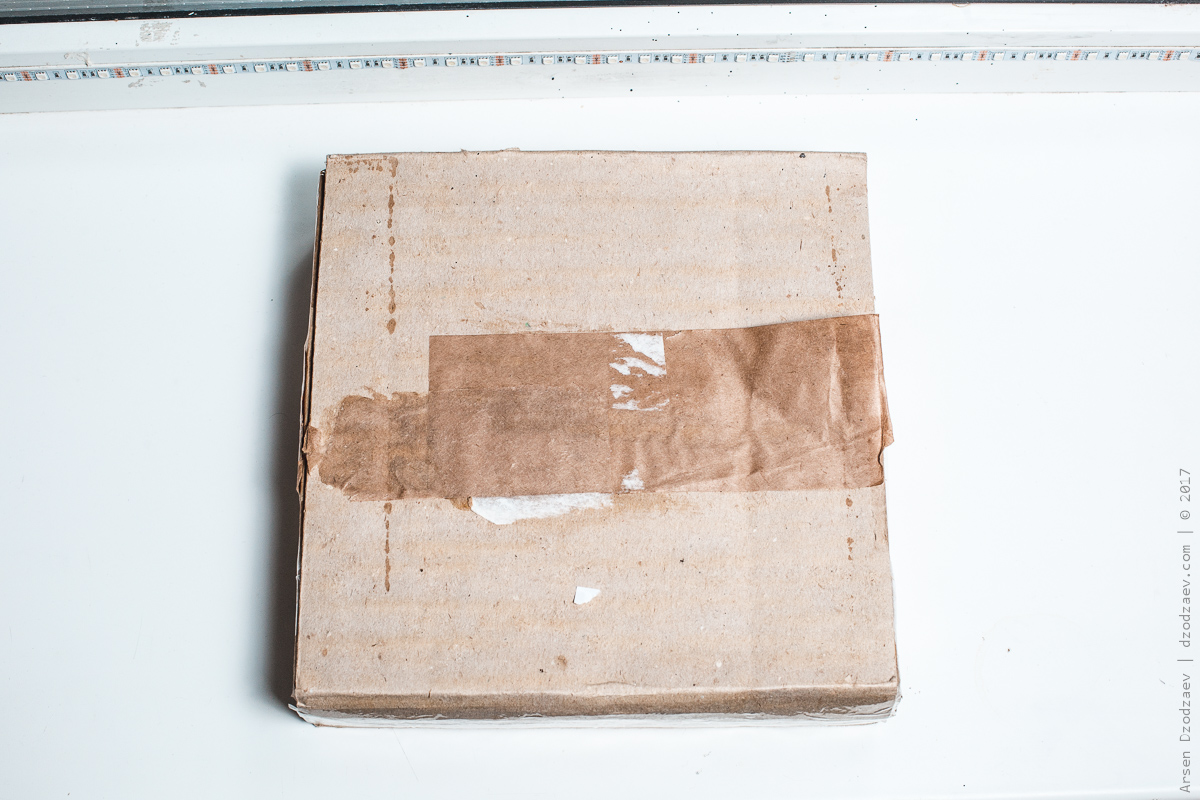
 Original packaging
 Compare with Arduino board
 Compare with iPhone 6S
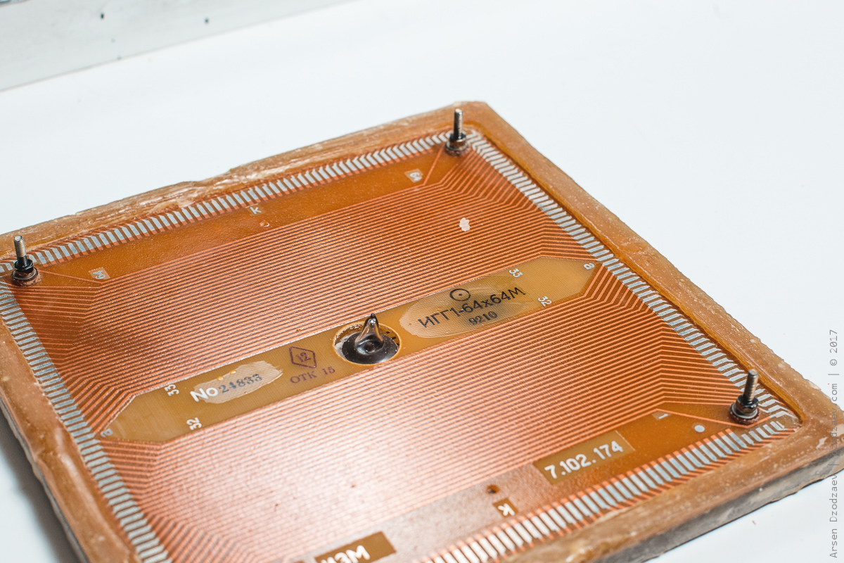
 Serial number
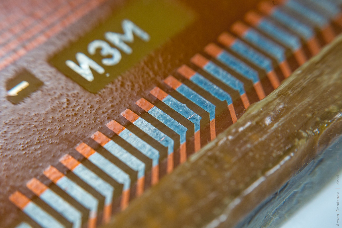 Pins
Pins


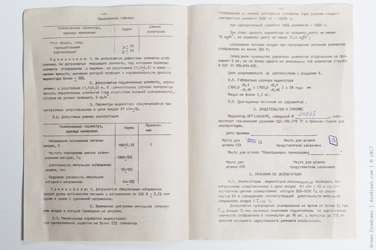
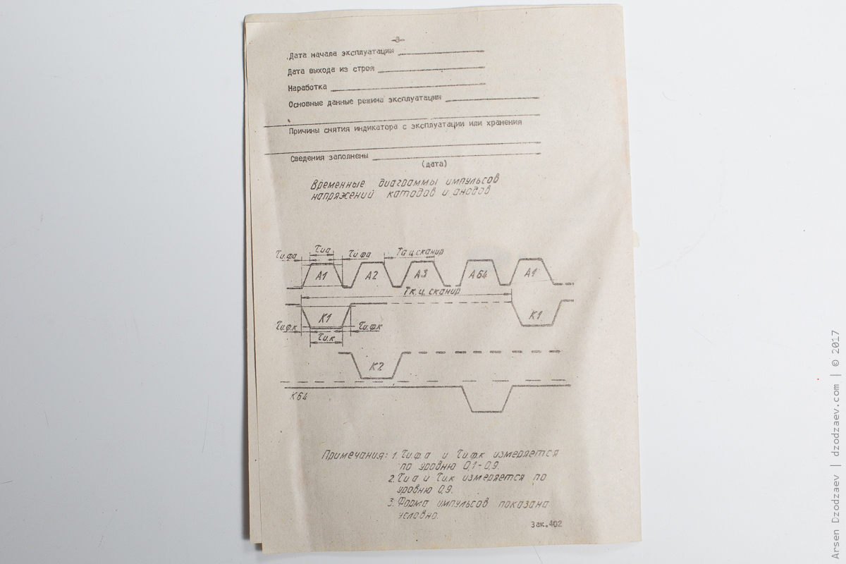
 Original datasheet

Discussions
Become a Hackaday.io Member
Create an account to leave a comment. Already have an account? Log In.
That is awesome!
Are you sure? yes | no
tough, old, Soviet gadgets capable of surviving a nuclear explosion ) good luck to run it!
Are you sure? yes | no
For convenience I've created a project page to log what I've found so far :
https://hackaday.io/project/46302-1-64x64m-adventure
Are you sure? yes | no
I’d love to know if you get this working too. I’d love to use one of these but the supply voltage is beyond my skills 😪
Are you sure? yes | no
Can't read the Russian datasheet, and looking through the tech info on eBay I have a question. How do you select between the red and green colors for a pixel ?? Do the pixels alternate in color (red, green, red green, etc), such that you can only get 32 red and 32 green across or down ??? So that would make it a 32x32 for red or 32x32 for green, but not 64x64 for all red or green.....
Are you sure? yes | no
Yes you're right, it is 64x64 pixels, but 2 times a 32x32 specific color matrix. Red (orange) and green alternate on a chessboard way
It is shown at the second page of the datasheet, I don't read Russian neither, but I searched green (зеленый) and red (красный) with google translate.
Are you sure? yes | no
Thanks for confirming what I was thinking.
Are you sure? yes | no
I think I start to have the idea of how the anode driver works:
http://muth.inc.free.fr/temp/CaptureSpice001.PNG
Except the 10Kohm values visible on the video, the others resistor values are stupid guesses.
When input (V1) is at 0v, Q2 is 'closed', charging C1 and Q1 is 'open'. So output is at 180v (~V2)
When input (V1) is at 5v, Q2 is open, Q1 is closed, putting C1 in series to the 180v, out is at 360v (~V2 + Vc1).
Transistors might be high voltage BJT NPN such as the MPSA42.
As I don't have yet these transistors, however I've tested 'manually' to charge a tiny capacitor (10nF) at 180v, then placed it in series with the 180v power supply and one anode. One cathode at ground. And yes, a pixel is flashing :)
Are you sure? yes | no
These panels are inexpensive and available on eBay. I'd love to see you (or anyone else) get one up and running. The video @Muth linked to has a bit of a demo and the pixels have a really striking appearance!
Are you sure? yes | no
The DIP packages should be shift register of some sort.
I don't know the types of the transistors, npn, pnp, fet or... So far I can only see something such as : http://muth.inc.free.fr/temp/Capture001.JPG
I'm not enough advanced in this kind of electronic to really 'see' how it's working yet.
Are you sure? yes | no
I found this video on youtube : https://youtu.be/hXe-FHFUHzo
Apparently it is possible to drive the anodes at 300-400V from a ~180V source, using a capacitor discharge.
I'm trying to figure out the schematics, not easy but doable.
Are you sure? yes | no
Did you get this working? Just curious.
Are you sure? yes | no
Unfotunatley no, I dont have time to have fun with it:(
Are you sure? yes | no