 Valentyn
Over the past 10 years, we have witnessed the active development of the VR industry and efforts to implement it in various business and entertainment sectors. It quickly evolved from an exotic, incomprehensible, and very expensive novelty to a common accessory that almost everyone can afford. If you are familiar with platforms like VRChat, Somnium Space, or any other metaverse, you have probably heard of the concept of Full Body Tracking (FBT). This article is specifically about developing trackers. However, for those who have not yet had the chance to explore virtual worlds, I will try to give you an overview before getting to the essence.
A Bit of History. The first commercial VR headsets were essentially just displays with lenses to create a normal focal distance and implemented only three degrees of freedom (3DoF) through inertial sensors or a magnetometer. This allows you to look around but does not track your movement, similar to phone cardboards. The next development step in VR was the introduction of spatial tracking. For example, in 2014, Oculus was able to add an inexpensive and quite accurate tracking system to its new headset, the Rift DK2. Infrared (IR) LEDs built into the headset acted as points of interest for a simple computer vision system that took images from an IR camera and calculated spatial coordinates along with rotation angles, further refined by inertial sensors (IMUs). This allowed the user to freely move around the play area, rather than being anchored to a fixed position.
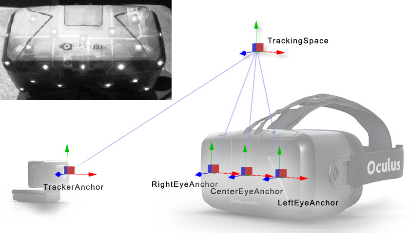
Fig. 1. Oculus DK 2, optical tracking system based on IR camera and LEDs.
Although this 6DoF system has its flaws, its relatively low cost makes it an excellent solution for mass-produced headsets like PlayStation VR or Oculus Rift. Moreover, this method allowed the inclusion of trackable controllers. And so, our virtual avatar has not only a floating head but also fully functional hands.
The next significant development in tracking systems was made by HTC in collaboration with Valve, revolutionizing everything by embedding a photodiode array into the headset instead of LEDs. Unlike all previous solutions, the new system introduced in 2015 as SteamVR Tracking does not use cameras, and the PC does not process any data. It was designed from the outset to provide room-scale position tracking without needing to connect sensors to the user's PC. The growing popularity of this system was also helped by the fact that the documentation for this system is open, as is some of the software.
Instead of stations based on IR cameras, new devices called, quite logically and succinctly, "Lighthouse" was introduced. If you want to learn more about their design and history, I suggest paying attention to Brad's video: “Valve's Lighthouse: Past, Present, and Future,” and here I will try to briefly explain their working principles. Positioned at opposite corners of the room, the lighthouses emit wide-angle two-dimensional IR laser beams throughout the room, doing this one axis at a time, meaning from right to left, then from top to bottom. Before each sweep, they emit a powerful IR light flash to synchronize. Each tracked device, whether it be a headset or controller, contains an array of IR photodiodes connected to a microcontroller (MCU), which measures the time between the flash and the laser hitting each photodiode. The tracking system uses simple trigonometry to calculate the position of each sensor with a fraction of a millimeter accuracy.
Fig. 2. Lighthouse tracking.
One of the main advantages of this approach is that now an unlimited number of devices can be tracked in the room, as long as the laser beam reaches at least a few photodiodes. A little later, the first Vive Tracker was introduced, featuring a standard 1/4 inch thread mount, meant to be attached to almost anything, whether it be a camera to track its position in the studio or a baseball bat to capture the trajectory of a swing. But the most logical solution seems to be – if our virtual character has a flying head and hands, why not add other limbs?
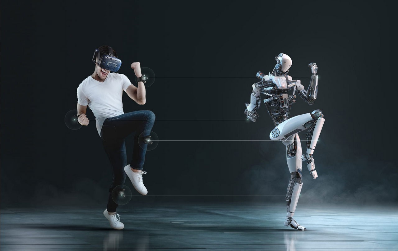
Fig. 3. HTC Vive trackers.
Do you need it? I want to note right away, that even if you own a VR headset, FBT technology is niche and might not be necessary for you. In dynamic games, even the presence of a body in the character, which falls into the user's field of view, can create discomfort for some people. Therefore, Valve's approach to implementing game mechanics in HL: Alyx seems quite rational and correct to me. However, it's a different story for social platforms/games where it may be important for users to convey emotions, gesticulate, and just immerse themselves in the game as much as possible. If you have the opportunity to travel through the worlds of VRChat, you will immediately understand who the target audience for FBT systems is, as hard as it may sound in words:

Of course, it's not just games; this technology is also actively used for creating animations, capturing movements of VTubers, etc.
What solutions already exist? Today, many FBT systems differ both in fundamental working principles and in the quality of implementation. On the SlimeVR project page, there is a good comparative table. While I have questions about some of the data in it, overall, it well reflects the differences in popular tracking systems:
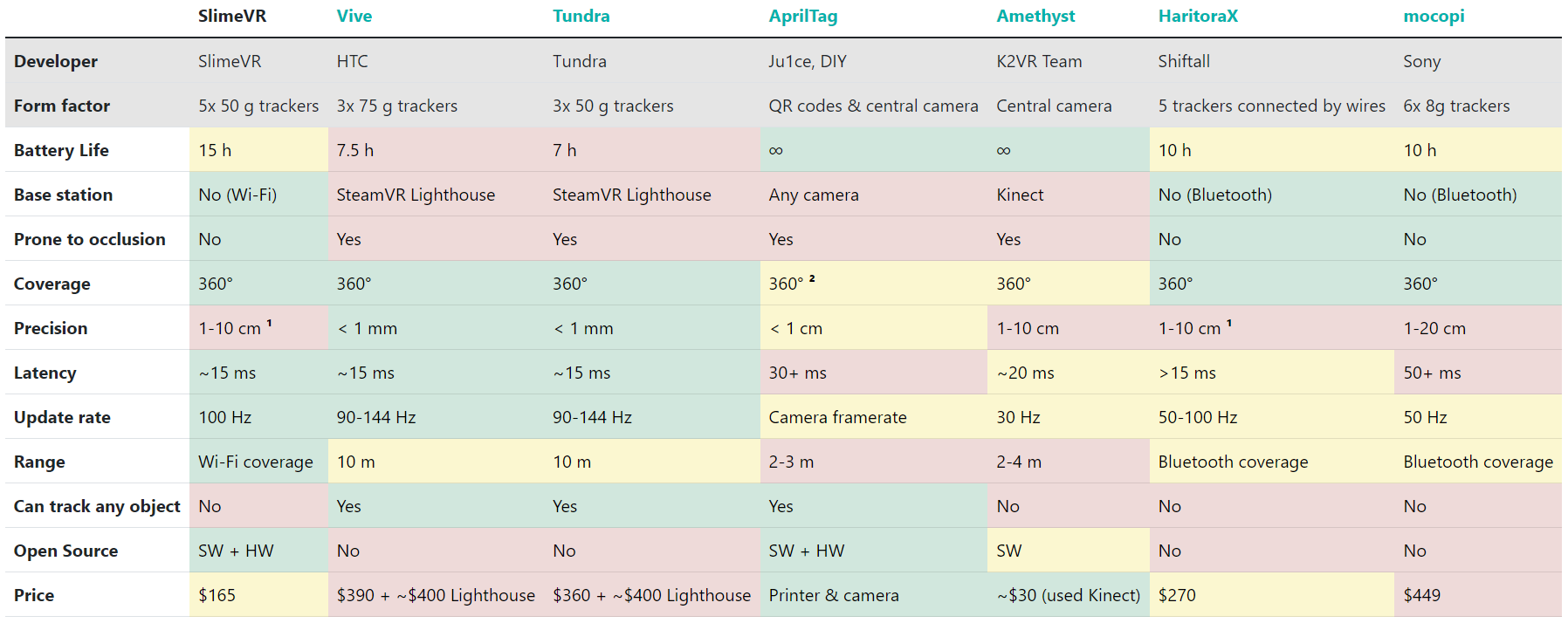
Fig. 4. SlimeVR comparison table.
From it, we can identify three main groups:
- Tracking with base stations (Lighthouse): Vive, Tundra. This method is still the most accurate today, but with the industry's rapid shift to inside-out tracking (using cameras built into the headset), not every VR user has base stations, which require at least two for reliable coverage. Also, you won't be able to wrap yourself in a warm blanket in the cold winter.
- Camera-based tracking: AprilTag, Amethyst, Driver4VR. Probably the most accessible method for the average user, special software captures the image from a regular camera and, using a neural network, finds the position of the user's limbs, or Kinect, which also uses a camera with an IR dot projector. The main disadvantage is accuracy, and while standing in front of the sensor you likely won't have problems, just take any non-standard position or even sit on a chair, and the model twists randomly.
- Inertial trackers: SlimeVR, HaritoraX, mocopi. Each tracker monitors its rotation in space, and the software uses your proportions and the coordinates of the VR headset to calculate joint angles and estimate limb positions. Speaking more technically, the technology relies on absolute orientation sensors, a calibrated skeleton model, and forward kinematics.
I would like to focus more on the third category. Inertial trackers are attractive due to their low price, lightness, ease of wear, and autonomy. Since they do not depend on cameras or base stations, they can track a wide range of movements without being obscured or blocked from view, which would result in a loss of tracking by external sensors. On the other hand, they are less accurate, require periodic reorientation, and you need more of them. For example, a set for the lower body includes at least five trackers – two on each leg and one on the waist, or seven if you also want to track foot position. In contrast, for a similar task, only three Vive trackers are enough. However, even considering a larger number, the total price of the set still comes out significantly lower than the cost of Vive or Tundra tracker sets.
A good example of the implementation of this technology is the small Estonian startup SlimeVR, which gained significant popularity in the VR community thanks to open-source software and easy assembly.
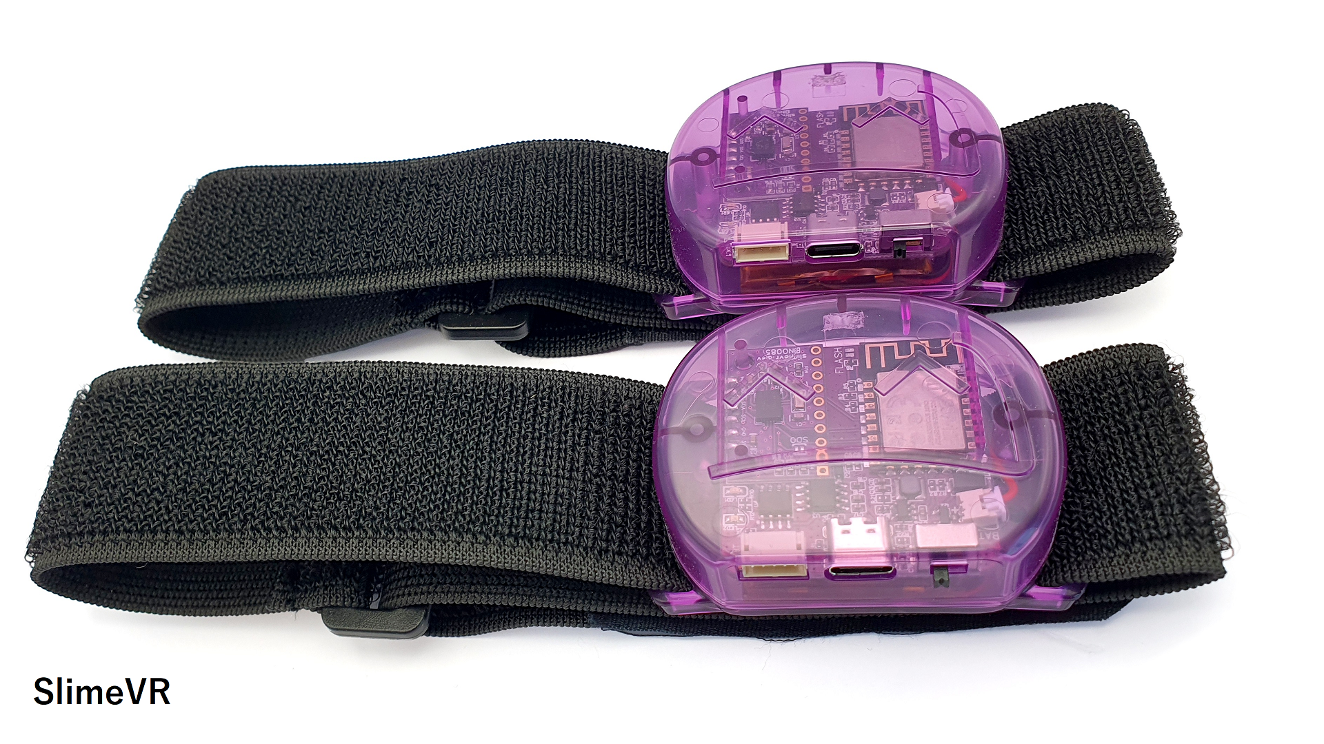
Fig. 5. SlimeVR serial model.
The base uses the ESP8266/ESP32 module, which connects to WiFi. This is both good and bad. On one hand, you have good coverage, directly dependent on your router, as well as a device limit in the network. On the other, this method is much more energy-consuming than, for example, BLE. Also, in the pursuit of universality, you can lose unique features that a certain sensor might offer.
The main blog topic. I was not satisfied with certain shortcomings inherent to SlimeVR or HaritoraX, and the desire to make my version, as they say "Just for fun," prompted me to start this small project.
The following points are key technical aspects that I would like to see reflected in the final version of the device:
- Small and lightweight form factor for comfortable wear;
- Active working time of at least 48 hours;
- Three power modes: active tracking, sleep mode with motion detection (no need to manually turn the tracker on and off, it understands when it is being worn), deep sleep mode (activation only by pressing a button);
- Ease of setup and connection;
- Low gyro drift, no more than 4 degrees per hour;
- The presence of an accurate magnetometer to compensate for drift;
- Refresh rate of 60Hz;
Before starting work on the design, let's decide on the choice of key components:
- Microcontroller. As I plan to power the device from a battery, and a very small one at that, the ESP32, which consumes about 90mA even in Rx mode, is clearly not my choice. Moreover, there is another important reason, but more on that later. Having the most experience working with STM32, my choice fell on the STM32WB series. These are ultra-low-power MCUs that support the BLE 5 standard, as well as wireless protocols 802.15.4. Specifically, the STM32WB15CCU6 was chosen due to its low price of $2.5 and its availability in JLCPCB's stock. There is no USB in this version, but the firmware can be updated via OTA, which is only more convenient.
- IMU. This can be said to be the heart of the tracker, as its final accuracy depends mostly on it. First of all, we are interested in the scale, sensitivity, and noise level of the gyroscope (mdps/rtHz), the same applies to the accelerometer. Although drift can be partially compensated for by the magnetometer, it should not be relied upon too heavily. All sensors will be subject to high levels of noise. For example, movement-induced acceleration will lead to a shift in the controlled direction of gravity. Therefore, choosing and configuring the orientation algorithm is equally important. The task of the orientation filter is to calculate a single estimate of orientation obtained by measurements from the accelerometer, gyroscope, and magnetometer. The Kalman filter has become the most recognized for constructing such algorithms, but there are other more modern ones, like the Madgwick or Mahony filter.
On one hand, I want to implement a rather professional solution; on the other, I do not want to dive again into the intricacies of setting up filters, quaternion equations, etc. After all, this was planned as a weekend project, not something I'm ready to spend huge time resources on.
ICM-42688-V, that's the solution! This MEMS sensor comes with an Advanced Sensor Fusion Library from TDK, providing high-precision orientation output data, and moreover, allows easy integration of any external magnetometer. But an unpleasant feature of this library is that it comes as several headers and precompiled files for different platforms, and their list is quite short: Cortex M0, M3, and M4. Thus, ESP is out again. For STM32, everything is simple, our chip is built based on the CM4 core, you only need to link the library in your favorite IDE and implement basic functions such as reading and writing registers, as well as obtaining timer values.
The counterpart of this MEMS is ICM-42688-P, the same pinout, the same noise and accuracy, and practically an identical register map. But! It will not work with the ASF library!
Jumping ahead, let's try to at least estimate the accuracy. First, we open the first library for the 42688-P that comes to mind, where the author immediately presents his measurements of drift in a calm mode using the Madgwick filter and basic calibration:
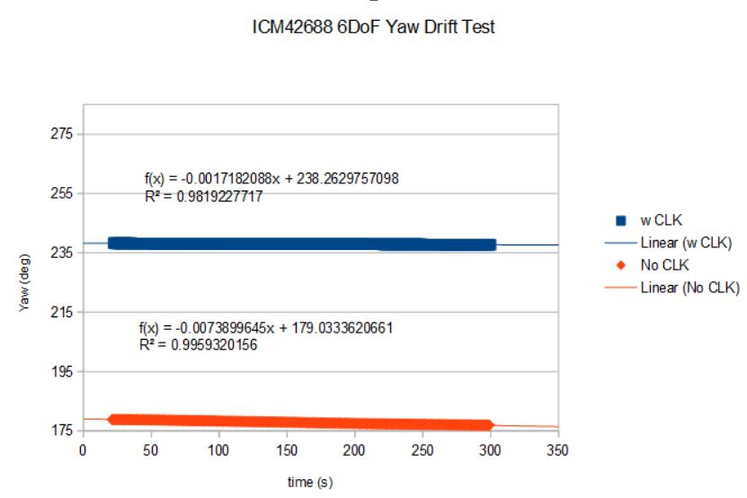
Fig. 6. ICM-42688-P drift.
To increase accuracy, the manufacturer recommends providing an external clock signal, and indeed, with an external quartz generator, accuracy increased by four times! The drift is 6 degrees per hour, which is quite good for relatively cheap MEMS.
But what can be obtained in practice with 42688-V and the ASF library? For this, I implemented all the low-level functions and ran the algorithm on the devboard. Calibration is very simple - randomly rotate the sensor until the algorithm reports that it has established values for all axes. I was too lazy to draw graphs, so here are the Euler angles at the start of the experiment:
Euler: 350.377594, -0.133775, -1.941636
And an hour later in a stationary state:
Euler: 351.549072, -0.099869, -1.850119
We see that the drift along the Yaw axis was only 1.16 degrees. Even for a static position, this is incredibly small. But we should not be too optimistic, in dynamics this number should be higher, I do not have access to the necessary equipment, but when trying to quickly rotate the IMU for a minute, and then return it to its initial position, I did not notice significant deviations. Therefore, the verdict: ASF works and works very well, even without a connected magnetometer.
- Magnetometer. Here everything is simpler, we look at the dynamic range, solutions in the range of 4-16G (gauss) will be optimal. The best I could find for sale is MMC5983MA, and its price of $2-3 makes it very attractive.
Design. I had a certain image of the design in my head by this stage, it remained only to transfer it to 3D using SolidWorks and see how technological it is for production. I would like to note in advance that I do not plan to print the case on a home FDM printer, but prefer to outsource such work to JLCPCB. For just $3, they can print all the parts on an MJF printer with excellent quality.
Without wasting time, let's move straight to the result:
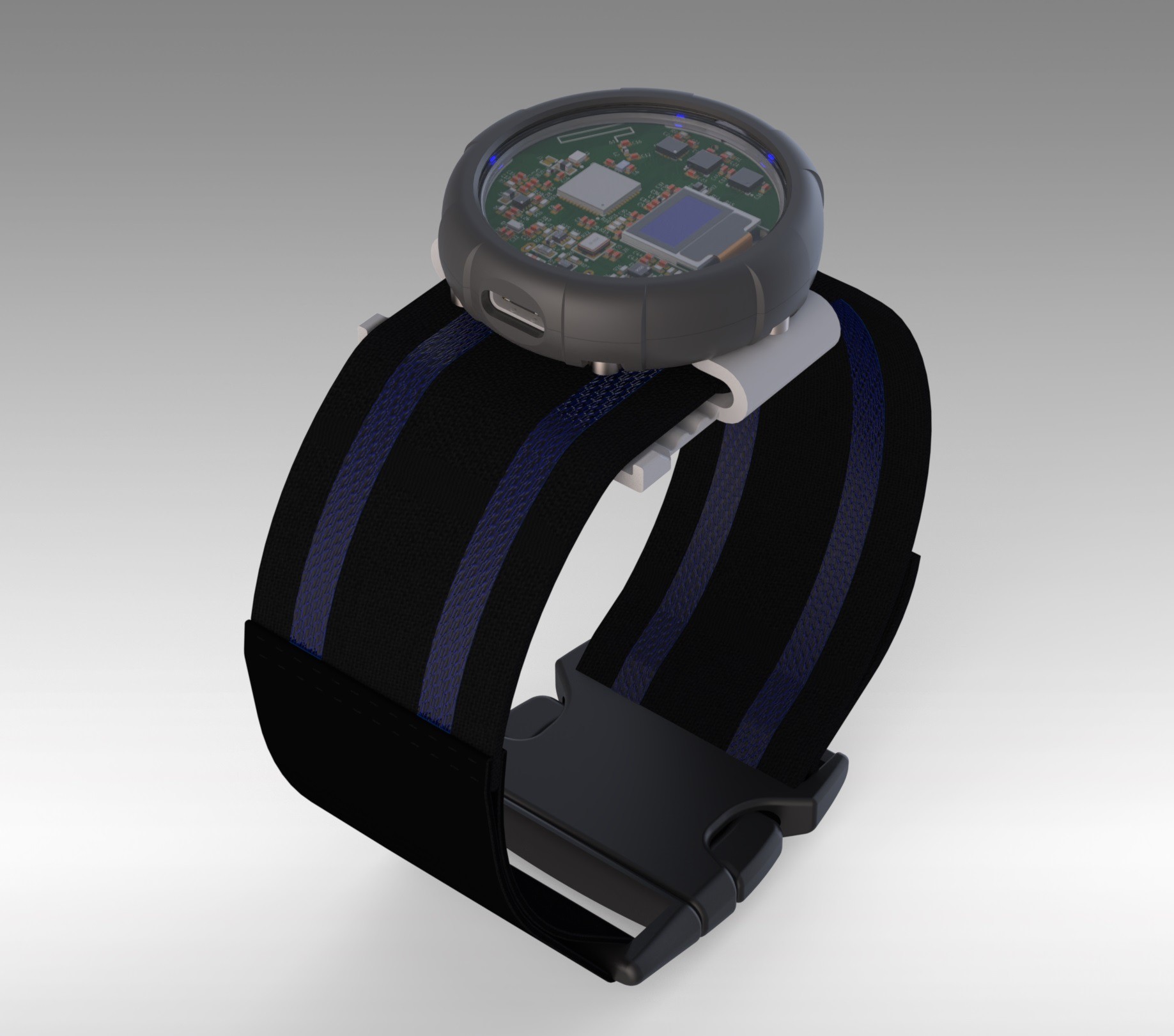
Fig. 7. Prototype design render.
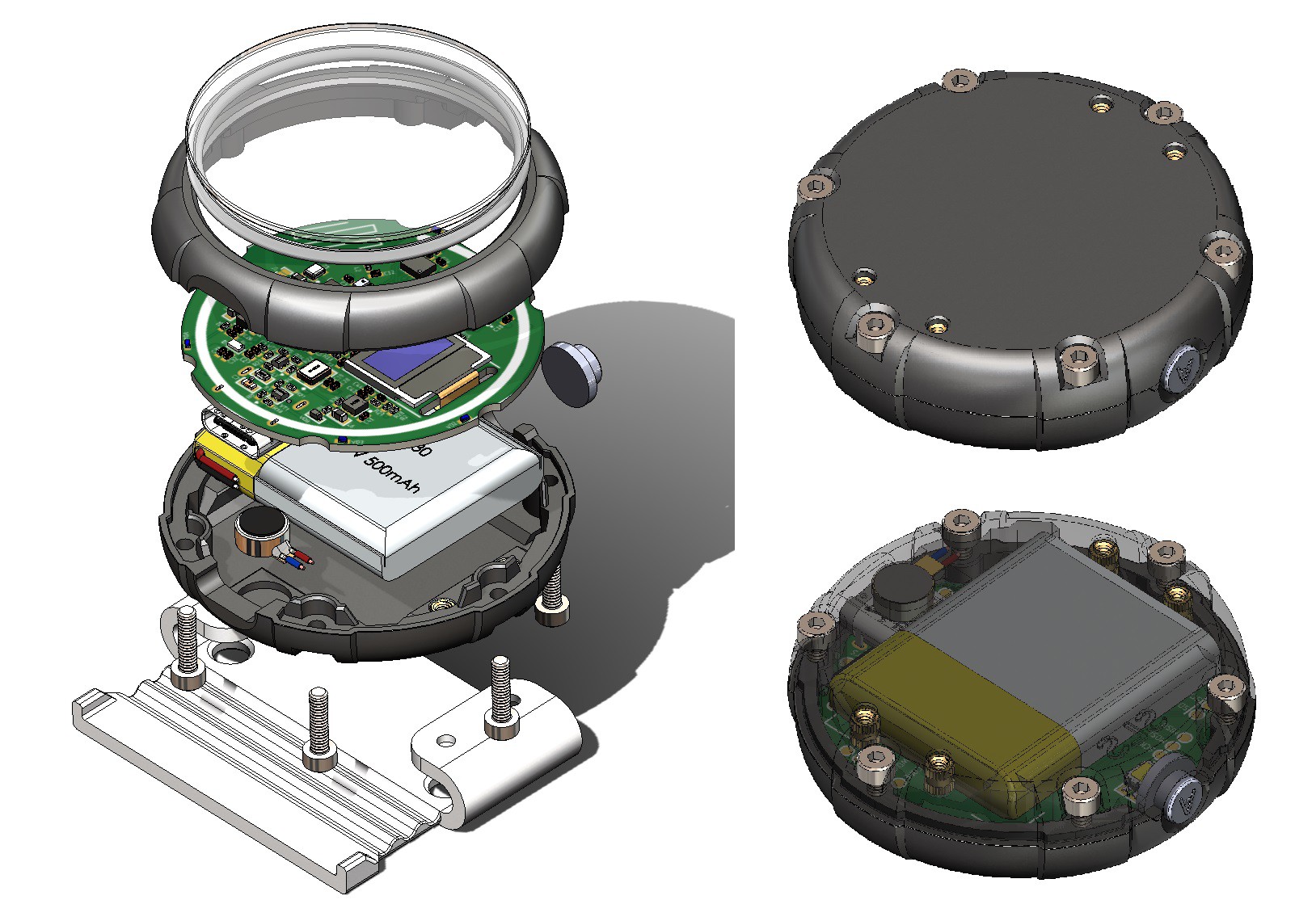
Fig. 8. Prototype assembly.
The design turned out to be practically in the form factor of a wristwatch. The maximum diameter of the case is 46mm, and the thickness excluding the strap mount is 11.6mm. The structure has four printed parts: the lower and upper halves of the case, the strap buckle, and the button. I wanted to make a "geek" design, so the printed circuit board (PCB) is located under transparent mineral glass, sturdy enough not to be easily broken, and in case of a strong impact, it will not shatter into small fragments, like most watches. The pressure to the upper part of the case and the gap between the glass and the PCB is provided by a silicone sealing ring with a cross-sectional diameter of 2mm, when designing the board, it will be necessary to ensure that no component is higher than ~1.6mm. Also, the ring is semi-transparent and will partially diffuse light, so we can play with the backlight around the perimeter (for example, add battery charge indication). In the lower part of the case, four insertion M2 brass nuts were added for mounting the belt buckle or any other attachment. The battery thickness was chosen so as to position the USB and button approximately in the center, and it is 6mm, with a capacity of 500mAh. As we can see, the layout turned out to be quite compact, and all details can be easily ordered from China.
Designing the schematic and PCB. Here everything is quite simple, we have several sensors, DC-DC converters, a charging controller, etc. Just remember, the device is powered by a battery and we want to save as much charge as possible, so even for the resistor divider for measuring the battery voltage, I put MOSFET switches. Carefully study all datasheets, interesting lines for us: quiescent current, sleep mode current, etc., this will give some idea of consumption in different operating modes and about what can be put into sleep mode and what will have to be turned off completely. The Altium project will be published later. A week of evening work in front of the computer monitor and here is the actual design of the board:
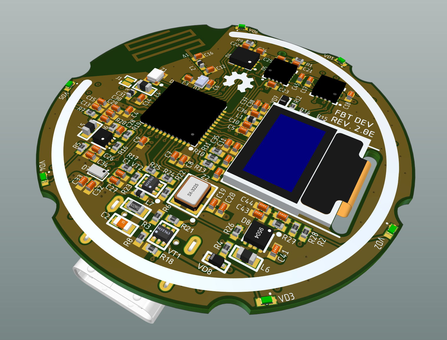
Fig. 9. PCB top layer.
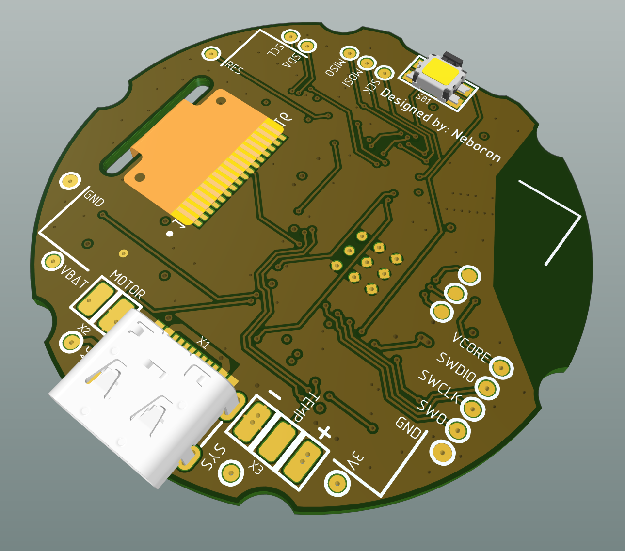
Fig. 10. PCB bottom layer.
The round board with a diameter of 40mm accommodates all components including the antenna, a tiny OLED display with a resolution of 72x40 was added more for the sake of convenience in debugging. All DC-DC converters and the charging controller are located on the side of the USB. On the opposite side, away from theoretical sources of noise and magnetic parts, sensors were placed. We can see that there are now three, another footprint was added for a more accessible magnetometer, it's not much worse than MMC5983, but at the same time, it's available in large quantities in JLC warehouse. On the back, there are the USB type C charging connector, the tactile button, and place for the LiPo battery, which is glued with double-sided tape.
Time to assemble everything. I made a final review for mistakes, prepared gerbers, CPL, BoM, and sent it to the factory. As always, I'm too lazy to prepare a proper BoM with LCSC/JLC component codes, so some I need to choose manually. The boards are more expensive than usual because I specified increased accuracy for the vias, but usually, there will be no problems even with the standard configuration of the order.
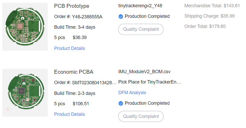
Fig. 11. JLCPCB order.
Assembling the first five prototypes cost only $106.5, but with not all components installed, to save money assembly was one-sided. USB, button, and display I can solder myself. It's clear that for a larger quantity, the cost of one tracker noticeably decreases. A preliminary calculation showed that for a batch of 100 trackers, the cost of one would be ~$25, including all plastic parts and the strap.
Approximately a week for production and another week for delivery, and here they are in my hands:
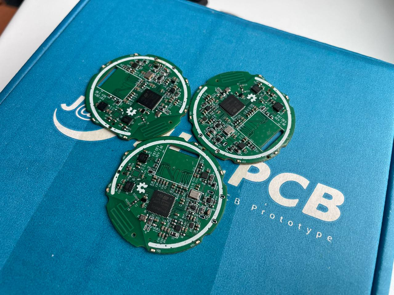
Fig. 12. Assembled boards by JLCPCB.
I solder the missing components and can begin to gradually bring each component to life (at the time of writing the article, I managed to get everything that lies on the I2C bus to work: display, charging controller, magnetometer). Plastic parts arrived in a separate parcel, this time in addition to MJF I ordered SLS, to compare print quality. In SLS, it is indeed slightly higher, but the surface is not smooth, feeling more like fine-grit sandpaper, so I will continue to use MJF.
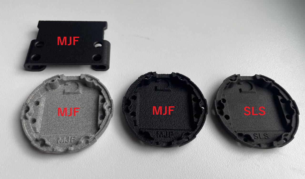
Fig. 13. Printed parts by JLCPCB.
I assembled the first prototype to see how all the parts fit together:
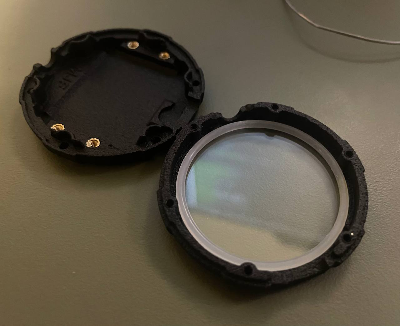
Fig. 14. Tracker assembly, step 1.
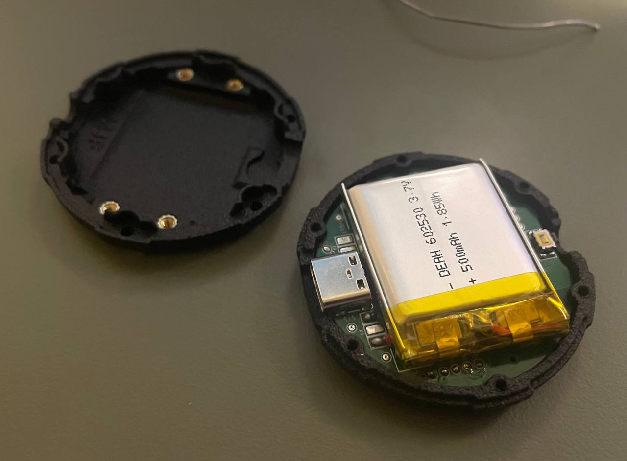
Fig. 15. Tracker assembly, step 2.
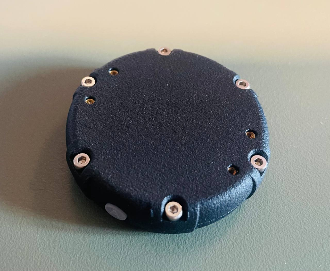
Fig. 16. Tracker assembly, step 3.
Everything fits perfectly, there are only minor corrections for the next revision, such as reducing gaps. A few more photos of the assembled device:
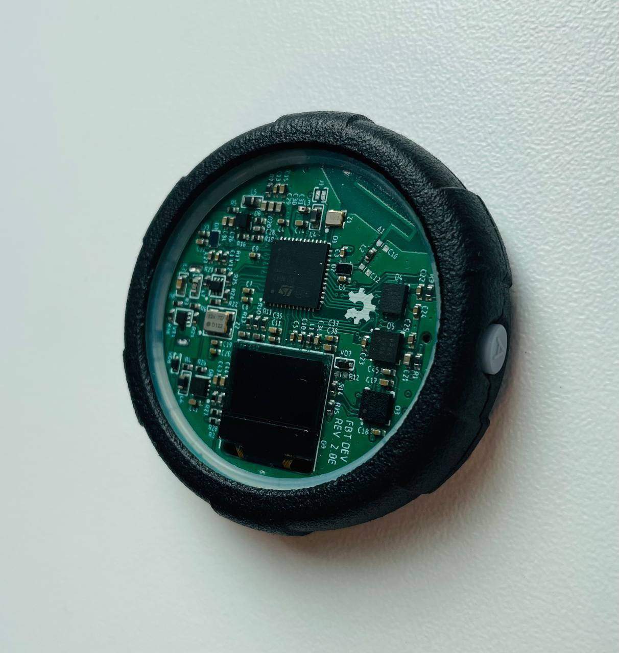
Fig. 17. Assembled tracker.
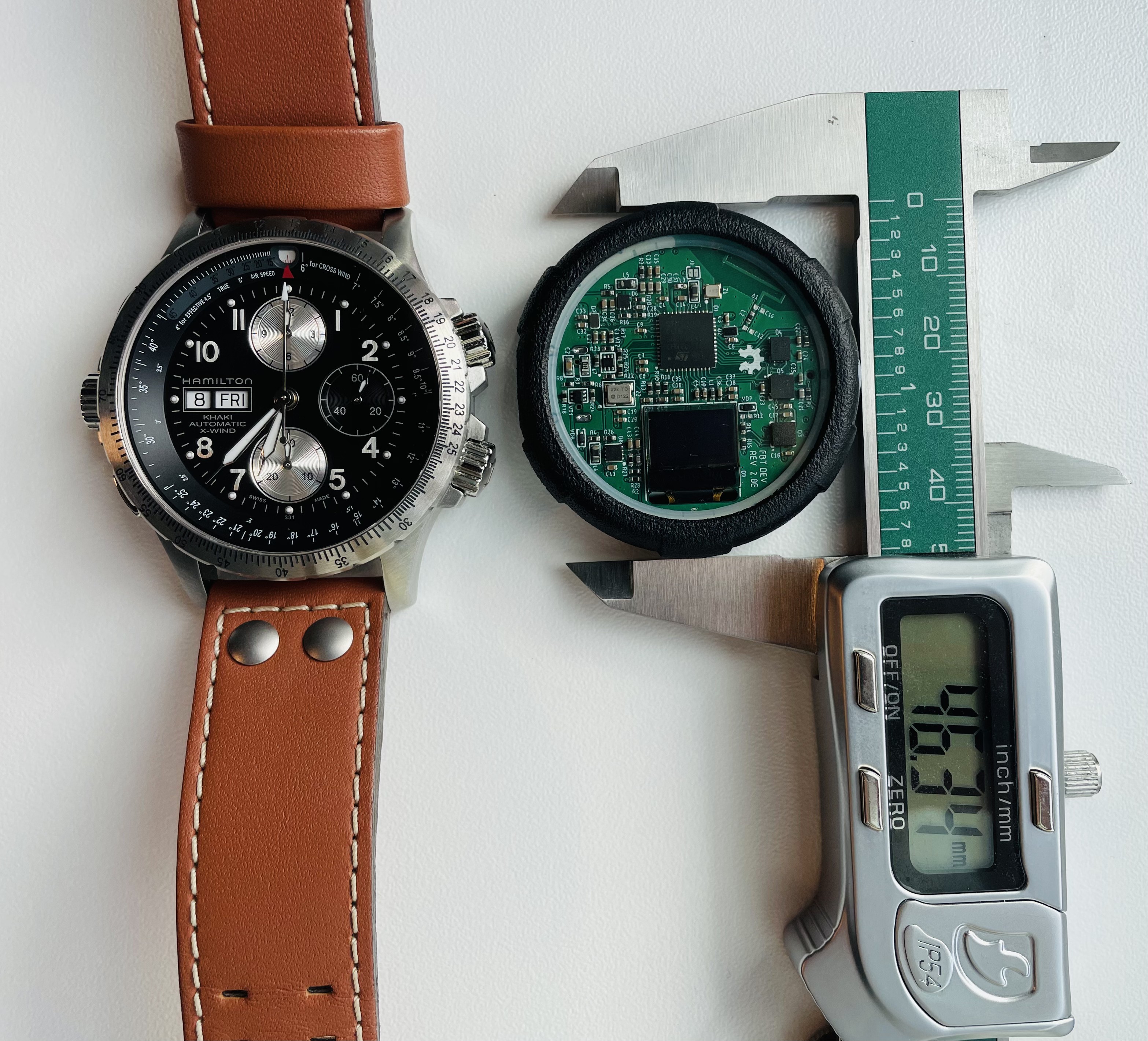
Fig. 18. Tracker size comparison.
What's next? This article was written to talk about the current status of the device, I plan to release the second part soon, when some software parts will be ready. There is a lot of work ahead in software development, when the tracker is brought at least to a basic working state I will open my GitHub repository. The design is not final, I plan to change the color of the printed circuit board to white (green was the cheapest), as well as the brightness and color of the LEDs. But I must warn you, that this project is one of the lowest priorities on my list, so I may have to freeze it for some time.
P.S. Initially, I wrote this blog in Ukrainian, translated it into English with ChatGPT, and made a quick check, but some minor mistakes may be present.
Discussions
Become a Hackaday.io Member
Create an account to leave a comment. Already have an account? Log In.
You should try using my firmware as a starting point! It's written in rust and already works on cortex m devices like the nrf. I've been thinking about rewriting it now that async fn in trait is stable, and this platform sounds like an excellent choice.
https://github.com/SlimeVR/SlimeVR-Rust/tree/main/firmwareAre you sure? yes | no
Thank you, it looks nice. You did a very good job writing this firmware. BTW, how are you connecting the NRF to the SlimeVR server? I've come to the conclusion that Windows is not friendly for BLE devices, so I have an Android app serving as a bridge between the trackers and the SlimeVR server.
Are you sure? yes | no
Hello! For current versions of SlimeVR with nRF it actually doesn't use BLE, it is using ESB and connects to a receiver which is plugged into the computer.
https://github.com/SlimeVR/SlimeNRF-Tracker
https://github.com/SlimeVR/SlimeNRF-Receiver
SlimeVR has a Discord server if you are interested also
Are you sure? yes | no
Always looking to improve my tracking system, and have more to use in my content creation, these trackers could be my solution. And at a price point that is below even the SlimeVR trackers,.this could cause quite the stir in the VRChat community
Are you sure? yes | no
Ngl I would love to buy a pair of these, I have been looking for an affordable, and working tracking solution for some time now.
Are you sure? yes | no