 teardownit
As you know, a data cabling system consists of different segments. To connect them all and bring the data connection to the end user, it is necessary to make a certain number of crossings. Often, staff forgets to disconnect "old" lines. As a result, over time, parallel branches appear, and their presence can have a detrimental effect on the quality of services.
BRANCHES AS A SOURCE OF PROBLEMS
Parallel branches can make it difficult to serve clients and ensure system functionality. With the introduction of digital systems, the search for parallel branches becomes an increasingly important task since they negatively affect the operation of digital transmission systems and, even if in most cases they are relatively short in length, nevertheless lead to significant problems. The bramch creates a second path for digital signals transmitted on the main line, which travel along the branch and are reflected from its open end. Reflected signals (echoes) enter the main line, where they are mixed with "good" digital signals and negatively affect the quality of the transmitted data. Therefore, to ensure correct operation of the digital line, the branches must be disconnected completely.
When connecting to analog lines, branching also creates problems. For example, if there is a fault on such a branch, it may show itself in the form of a decrease in the quality of the transmitted signal.
Finally, unknown branches can affect the accuracy of diagnostic equipment, for example, when measuring cable capacitance and estimating the distance to a break using a capacitive bridge. An unknown branch increases the combined capacitance of the cable pair and causes a measurement error: for the tested pair, the calculated length will be greater than the actual length.
It is very important to have full information about all the parallel branches available on the line in order, if necessary, to select the correct algorithm for troubleshooting and eliminating the problem.
SEARCHING FOR THE LOCATION OF THE BRANCH CONNECTION
The capacitive bridge is the device most often used to measure the length of a cable that is open at the far end. Unfortunately, it only allows one to estimate the total length of a cable pair, including all parallel branches.
Using multi-function devices (combining a capacitive and resistive bridge), it is possible to calculate the length of the branch cable due to the ability to compare the length values obtained from measuring the cable capacitance and the resistance of the loop.
Pic main_img_p7621_thumb.png
In this case, an OTDR is the most optimal and, moreover, the only device that allows one to find the locations of branching, measure the lengths of the branches, and determine the distance to them.
However, in practice, cable analyzers that combine the functions of a reflectometer and a multi-function instrument are more convenient. The implementation of two measurement methods (reflectometric and bridge) in one device allows for comparison of the results obtained for more accurate fault localization.
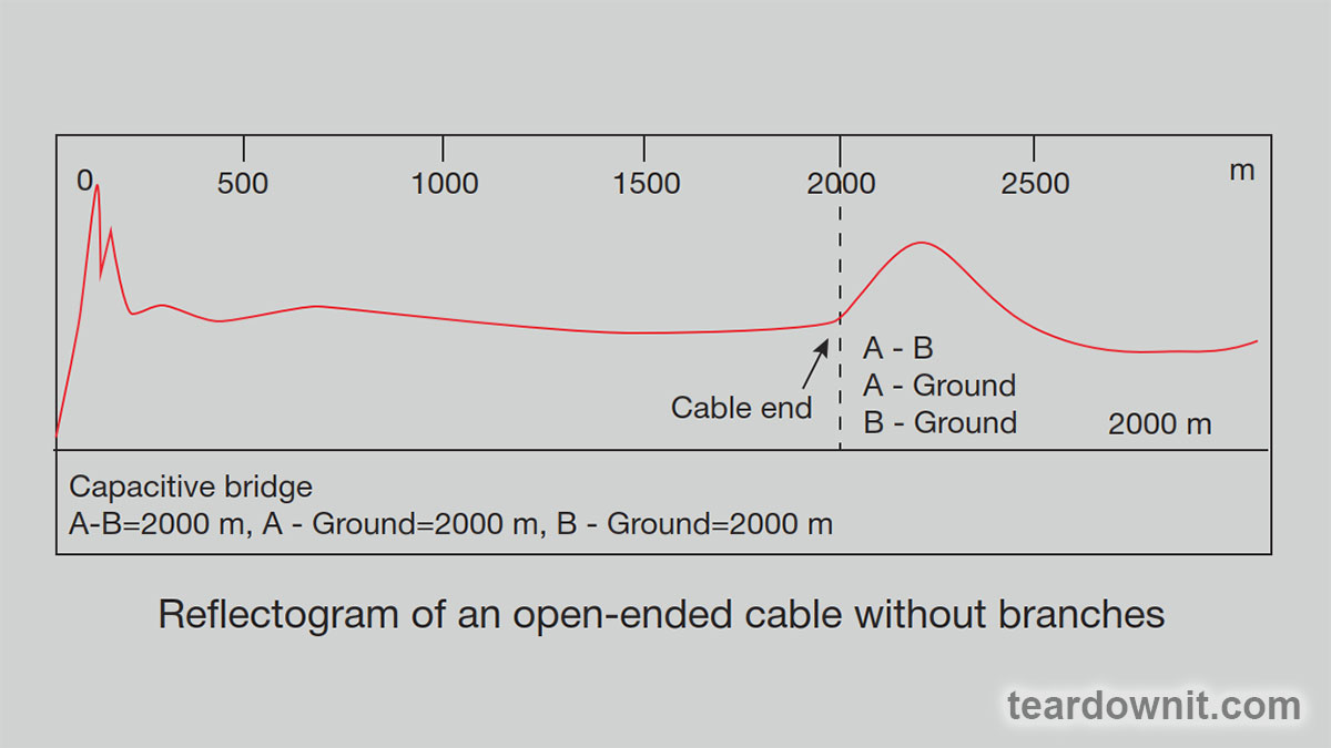
The classic branch reflectogram is similar to the one for testing a damaged cable, the only difference being that the reflection of the signal from the branch is a straight line rather than a curve.

As an explanation, let's look closely at the reflectograms for an open-ended cable section without a branch and a cable section with one (it is located at a distance of 3385 ft). The corresponding measurement results using a capacitive bridge were transferred to the reflectometer for direct comparison and accounted for. Note how the presence of a branch affects the measurement results of a capacitive bridge—in particular, how the cable section with a branch distorts the pulse reflected from the open end of the cable at a distance of 6500 feet. This occurs because part of the energy of the reflectometer signal was lost passing through the branch. The ideal way to view these graphs simultaneously is to use a dual-channel OTDR to connect and compare the "good" and "bad" cable pairs back-to-back.

Just as echoes affect digital signal transmission, parallel branches affect cable reflectograms. Interpretation of the reflectogram becomes significantly more difficult if two or more branches are connected to the pair under test.
The following graph is similar to the one shown in the previous figure, but in this case there is an additional branch at a distance of approximately 5400 feet.

The open end of the cable at a distance of 6500 feet is almost invisible on this reflectogram since the energy of the reflectometer test pulse is spent on passing two branches. If there are multiple branches connected to the cable under test, the best strategy is to locate the first one, access its location, and only then locate the next branch. This procedure should be repeated until the locations of all branches have been found.
Let's get to conclusions. Branches obstruct the operation of digital systems. The search for branches and their subsequent removal is extremely important to ensure the high quality of the digital services provided.
In order to make sure that the distance to the nearest branch corresponds to the standard for digital lines (maximum and total length of branches), one can use the following algorithm:
- Check the distance to the nearest branch.
- Check the length of the cable branch.
- Check the total length of all branches found.
Discussions
Become a Hackaday.io Member
Create an account to leave a comment. Already have an account? Log In.