 Super Circuits
If you know a bit about electronics than you must have seen non-inverting and inverting operational amplifier circuits. This article shows how versatile simple op-amp voltage follower can be.
You can implement this circuit with transistors if you do not have an access to an operational amplifier IC and wire wrap sockets:
https://www.instructables.com/id/Transistor-Sensor-Amplifier/
https://www.instructables.com/id/Recycled-Transistor-Amplifier/
You can see the circuit working in the videos:
Light Motion Sensor and Light Detector
Touch LED
Infra-red Receiver/Remote Control Tester
Frequency LED 1
Frequency LED 2
In the video you see that op-amp saturation voltage would not allow the LED to turn OFF. The minimum supply voltage must be 4.5 V. However, I used a 6 V power source.
Step 1: Design the Circuit
This circuit does not waste any resistor on feedback. An op-amp with zero resistance feedback does not need capacitors and has a high frequency bandwidth. A high resistor feedback will also limit the circuit applications. However, this circuit can only amplify current source inputs and does not amplify voltage sources.
I drawn the circuit in https://easyeda.com online simulation and PCB design software.
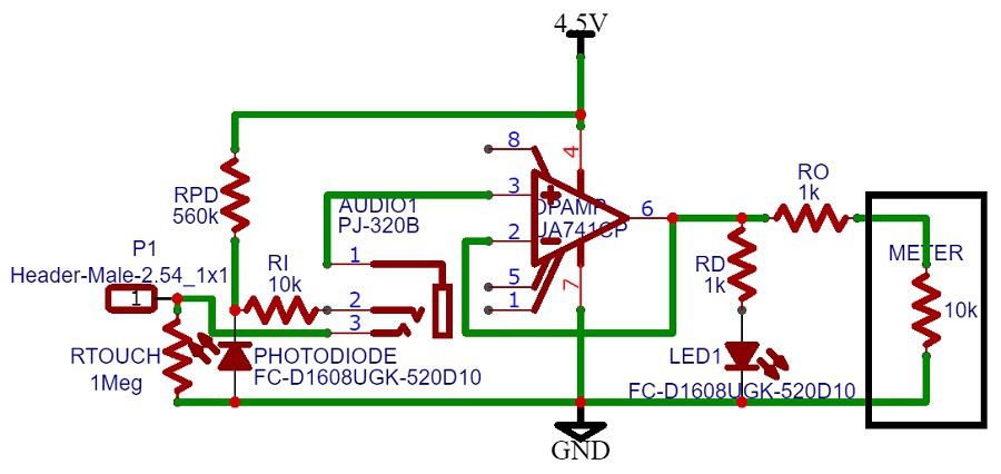
The Ro resistor is used for short circuit protection to prevent op-amp failure. Ri is used to protect the photo-diode from short circuits because op-amp input wire can be connected to power source or the photo-diode circuit output can be accidentally grounded. In both of those instances the photo-diode will fail, unless a 10 kohm resistor is placed in series (shown in the circuit diagram). A similar circuit was implemented for the infra-red receiver. Rtouch resistor is used prevent op-amp saturation due to disconnected inputs for the touch sensor. I connected to oscillator directly to the op-amp input. Than means that negative voltage was entering the op-amp.
Step 2: Make the Circuit
I used the well known LM741, 8 pin op-amp. However, I did not have an 8 pin wire wrap socket in stock. I used wire wrap tool and a bit of soldering. The black transistor looking component at the bottom is actually an infra-red photo-diode. The normal light photo-diode is on the right of the circuit.
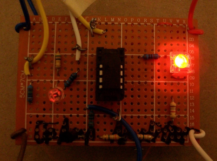
The yellow wire with a masking tape is connected to op-amp positive input terminal. The white wire is connected photo sensor circuit output. The blue wire at the bottom of the photo is connected to infra-red sensor circuit output. The blue wire at the top left corner was connected to signal generator and the other end to op-amp input (the yellow wire with masking tape). The yellow wire is touch sensor circuit output. You might not need to bias the op-amp input wit the Rtouch 1 Megohm resistor if the LED is OFF. I tried touching with one finger and two fingers (the other finger connected to power supply). The circuit worked with one finger when Rtouch was disconnected.
Discussions
Become a Hackaday.io Member
Create an account to leave a comment. Already have an account? Log In.