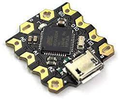
Even though it's the smallest Arduino board, the Arduino beetle still has all the features of the Arduino Leonardo. This board is an impressive complement to the Arduino technology's understated design. The Atmel Atmega32u4 microprocessor serves as its foundation. Modern technology developments have led to the development of electronic gadgets that are lighter, more portable, and capable of carrying out various tasks.
These tools are cheap and can be utilized by anyone without extensive training. Although every Arduino board also functions as a microcontroller, not every microcontroller is an Arduino board. The Arduino board has built-in features that can be used without other connected components.
Arduino Beetle Features and Specifications
The primary specifications and characteristics of the Arduino Beetle are listed below:
The board is miniature, measuring only 20 by 22 millimeters
Uploading and testing can be done directly using Micro USB.
Users will appreciate the V-shaped, big, gold-plated input/output ports, which are easy to twist wires onto and may be immediately stitched onto clothing using conductive thread.
Two honeycomb-shaped power interfaces with gold plating
BLINK indication in a magical light blue color
The system requires a 5V supply and operates at 16MHz.
There are ten digital I/O pins, five analog ones, and four PWM ones.
Currently, the Bootloader consumes 4 KB of the 32 KB of available Flash memory.
Cycles of Writing/Erasing: 10,000 Flash/100,000 EEPROM
20 years at 85°C and 100 years at 25°C for data retention
It features an ATmega32u4 microcontroller
Beetle: Minimize Your Arduino Projects
One recent development in Arduino-based simplicity is the DFRobot Beetle. Having the processing power of an Arduino Leonardo while still being around the size of a quarter, this little guy makes it easy to scale back your projects without sacrificing features.
Now that I've had some experience with the Beetle, I'll share the knowledge and expertise I used to connect it to a Bluetooth HC-06 module successfully.
Step 1: Introduction to the Arduino Beetle
DFRobot has the Beetle on sale for about $8; the more you buy, the cheaper it gets. Because of its micro USB port, the Beetle can be easily programmed and operates similarly to an Arduino Leonardo. I'll only talk about how to make it Bluetooth-enabled.
Step 2: Strength
Although the Beetle's specifications state that it needs 5V to work, it may also run on 3.7V. It is useful since most LiPo batteries are available in most hobby shops and run at 3.7V. For convenience, use Tenergy, but any 3.7V source will work. Make sure it doesn't go beyond 5V, or you risk damaging the surface elements.
Inconveniently, the Beetle lacks a dedicated battery port, so you'll need to supply external power via the micro USB port or soldering on the female connector yourself. However, we'll observe some power terminals in the following phase.
Step 3: Choosing a Power Distribution Point
Power can be supplied to the Beetle using two connectors. Each end features a positive and negative (hot and ground) power terminal. The Beetle can be seen starting up with the battery in the images above.
After a successful code upload to the Arduino Beetle, the LED stops blinking and remains solid blue until digital 13 is written to the high state. Replacing the hot and ground wires will cause your Beetle to overheat, perhaps melting parts.
Step 4: Bluetooth HC-06
The HC-06 remains one of my go-to Bluetooth modules due to its simplicity and reliability. This component sends information from the Beetle to a PC using TTL serial connection via a virtual COM port.
Connecting this module in parallel with the Beetle circuit means that both can share the same 3.7V LiPo battery. The fact that this module costs only $5 is another excellent feature. All of these modules come with a default pairing code of 1234.
Step 5: Enabling Bluetooth and Beetle
You may power the Bluetooth module by connecting the...
When it comes down to it, an operational amplifier is just a multi-terminal linear IC. Op-amps are voltage amplifiers with external feedback elements like capacitors and resistors connected between their input and output terminals. An electrical voltage amplifier with high gain typically has a single-ended output and a differential input. Op-amps are utilized in various products across different industries and fields of study, making them one of the most ubiquitous electronic components.
What is an Operational Amplifier?
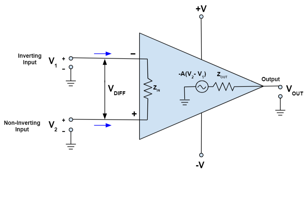
Operational amplifiers (op amps) are analog circuit components that take differential voltage inputs and output single-ended voltages.
Most operational amplifiers contain three connections: 2 high-impedance inputs and 1 low-impedance output. A negative (-) symbol is used to indicate an input that is inverting, whereas a plus (+) sign is used to indicate an input that is not inverting. The operational amplifier is a device used in signal chains, power supplies, and control systems that amplifies a voltage difference between its inputs.
Operational Amplifier Classifications
Operational amplifiers can be categorized in one of four categories:
Voltage amplifiers use input voltage to create an output voltage.
A current amplifier is an electronic circuit that takes in and outputs another current.
Transconductance amplifiers take in a voltage and produce a current as a result.
Transresistance amplifiers take an input current and transform it into an output voltage.
Since operational amplifiers are typically employed for voltage amplification, that's what we'll be discussing here.
Types of Operational Amplifier
Depending on the range of voltages that go into and out of the operational amplifier, there are three main types: Dual Supply, Rail-to-Rail, and Single Supply. See below for a breakdown of the input/output voltage ranges for the various op amp types.
Dual Supply Operational Amplifiers
Since operational amplifiers are designed to boost low-level signals, the VEE of a dual-supply op amp must be reduced to below -1.5V in order to accept a 0V input. Due to its frequent usage of a negative power source, the resulting operational amplifier is known as a dual supply operational amplifier since it requires both positive and negative supplies. The LM4558 is a dual supply operational amplifier. Learning about the LM4558 Pinout will help you to fully understand how to use it.
Rail-to-Rail Operational Amplifiers
Recently, there has been a shift toward reducing energy use, and as a result, more and more sets are being operated at reduced voltages. Op amps must also function at low voltages, however if VCC falls to almost 5V, an op amp with a single supply can only accept input 1.5V below VCC, which can be problematic. A Rail-to-Rail operational amplifier, on the other hand, can work normally even if the input voltage changes from VEE to VCC.
Single Supply Operational Amplifiers
While a negative voltage is required to input signals approaching 0V when employing a dual supply operational amplifier, a single supply op amp does not require this. Because it can function with an input signal as low as the ground level, it's also known as a ground sense operational amplifier.
Characteristics of Operational Amplifiers
Op-amps have a wide range of several crucial properties and parameters. More information about these traits is provided below.
Open-loop gain
In an op-amp, the gain amount attained in the absence of feedback is denoted by its open-loop gain ("A"). It indicates that the feedback loop is active. Except for when used with voltage benchmarks, an open-loop gain typically needs to be extremely big (10,000+) to be helpful.
Comparators that measure voltage do so by contrasting the voltages at their terminals. Voltage comparators can force the output to the rails in any direction, regardless of how minuscule the voltage difference is. Closed-loop systems benefit from high...
Similar to Arduino, ESP32 is a development board. Therefore, it offers all the capabilities required to construct your projects. You should be aware of who designed this board to comprehend it fully. You also need to know its primary purposes, how the ESP32 is used, and its technical characteristics.
Even while the ESP32 is greater than the Arduino UNO and ESP8266, that doesn't imply it's the best choice for every project. To use this microchip, we need to understand what it is, how it operates, and what makes it stand out from the crowd.
What is ESP32?
Espressif Systems developed the ESP32 using several low-cost, power-efficient modules and SoC.
The ESP32 is a successor to the ESP8266, a device that "surprised" Western experimenters in 2014. The first version of the ESP8266 was released on a module named the ESP-01, whose capabilities were mostly undocumented due to a lack of English paperwork. Immediately after the ESP8266's documentation was localized into English, a slew of curious tinkerers learned about the device's capabilities and swiftly gained widespread popularity.
The ESP32 design was enhanced in several areas over the ESP32 design. ESP8266 has WiFi. However, it provides BLE and Bluetooth. It comes with a dual-core design and is speedier. Additionally, it has an ultra-low power mode that is perfect for battery-powered tasks.
The compact ESP32 package offers numerous high-level interfaces, including:
Switches for antennas
Balun to regulate RF
Power booster
Amplifier with minimal noise
Modulated energy and air filtration systems
It uses extremely little energy because it has power-saving features like a synchronized clock and different operation modes. Because of its low quiescent current consumption, the ESP32 chip is perfect for use in battery-operated projects and Internet of Things uses.
ESP32 Peripheral Features/Workings
The accompanying Block diagram showcases the ESP32's impressive peripherals.
ESP32 Pinout Diagram:
The ESP32 pinout diagram for the ESP32 WROOM module is shown above; in it, various pins are indicated by their respective colors, which we will discuss in further depth below.
Digital pins
There are 34 digital pins all on the ESP32. These pins function similarly to the digital pins on an Arduino. Therefore, it allows us to connect external components such as screens, buttons, sensors, buzzers, and more to our creations.
Most of these pins support internal pull-up, high impedance, and pull-down states. They are, therefore, perfect for integrating matrix keyboards and buttons and implementing popular Charlieplexing LED control methods.
ESP32 WROOM module includes 25 GPIO pins, all inputs with or without a pull-up.
The "Recommended Operating Conditions" part of the ESP32 datasheet says that 40mA is the most current that can be drawn from a single GPIO.
Input only pins:
GPIO 34
GPIO 35
GPIO 36
GPIO 39
Pins with pull-up INPUT_PULLUP
GPIO14
GPIO16
GPIO17
GPIO18
GPIO19
GPIO21
GPIO22
GPIO23
Pins without internal pull up
GPIO13
GPIO25
GPIO26
GPIO27
GPIO32
GPIO33
ADC (Analog to digital converters)
Analog sensors can be read from and written to using the same pins on the pinout diagram corresponding to the analog inputs on an Arduino board.
The ESP32's 18-channel A/D converter and 12-bit resolution (0-4096) make it possible to collect data from various voltage and analog-based sensors.
With several analog sensors, you may still create very small linked applications thanks to this.
Analog input pins:
ADC1_CH0 (GPIO 36)
ADC1_CH1 (GPIO 37)
ADC1_CH2 (GPIO 38)
ADC1_CH3 (GPIO 39)
ADC1_CH4 (GPIO 32)
ADC1_CH5 (GPIO 33)
ADC1_CH6 (GPIO 34)
ADC1_CH7 (GPIO 35)
ADC2_CH0 (GPIO 4)
ADC2_CH1 (GPIO 0)
ADC2_CH2 (GPIO 2)
ADC2_CH3 (GPIO 15)
ADC2_CH4 (GPIO 13)
ADC2_CH5 (GPIO 12)
ADC2_CH6 (GPIO 14)
ADC2_CH7 (GPIO 27)
ADC2_CH8 (GPIO 25)
ADC2_CH9 (GPIO 26)
DAC (Digital to Analog Converters)
The majority of Arduino boards produce analog voltages via PWM signals. Two 8-bit D/A converters are present...
Industrial applications all over the world frequently use brushless DC motors. First, there are DC (Direct Current) motors and AC (Alternating Current) motors. As the name implies, DC motors that employ no brushes are called brushless. While it is clear that brushless DC motors have several advantages over conventional ones, what exactly are they, what is it used for, and how does it work? All of that will be explained in detail in this article.
What is a Brushless DC Motor?
Because its permanent magnets are in the rotor, a Brushless DC Motor does not require a commutator or brushes. Constant rotor rotation is ensured by monitoring the orientation of the rotor's magnetic poles and adjusting the coils' electrical current flows correspondingly.
The rotor won't turn if the motor is just connected to a power source; a drive circuit is necessary in this case.
Surface permanent magnet (SPM) motors have their permanent magnets affixed to the rotor's exterior, while internal permanent magnet (IPM) motors have magnets embedded within the rotor's core.
Brushless DC motors have several advantages over brushed DC motors, including reduced maintenance requirements because of longer service life and quieter operation.
Construction of Brushless DC Motor
Different physical arrangements can be used to build BLDC motors. These can be set up as 1-phase, 2-phase, or 3-phase motors based on how the stator is wound. The most popular type of motor is a 3-phase brushless DC with a permanent magnet rotor.
This motor's design is similar to traditional DC and 3-phase induction motors. Stator and rotor components are present in this motor, just like in all other motors.
Steel laminations are piled to form the BLDC motor's rotor, which carries the windings. These windings are inserted into slots that have been axially carved along the stator's inner perimeter. Either a star or a delta arrangement of these windings is possible. But most brushless DC motors feature a 3-phase stator with a star connection.
Several interconnected coils are used to build each winding, with one or more coils inserted into each slot. Each winding is dispersed across the stator's outer edge to create a balanced amount of poles.
Based on the capacity of the power source, a stator featuring the appropriate voltage rating must be selected. Low-voltage brushless DC motors are ideal for robots, automobiles, and other small actuation applications. Motors rated 100 V or above are utilized for automation and industrial systems.
Rotor
The rotor of a brushless DC motor contains a permanent magnet. Based on the need, the rotor might include two to eight sets alternating north and south poles. High flux density is required for maximal torque in the brushless DC motor. The rotor must be made of appropriate magnetic material to generate the necessary magnetic field density.
While ferrite magnets don't break the bank, their low flux density per unit volume is a drawback. Magnets made of rare earth alloys are widely utilized in innovative designs. Samarium Cobalt (SmCo), Ferrite and Boron (NdFeB), and Neodymium (Nd) are examples of these metal alloys. You can build the rotor with various core configurations, including a circular core with a permanent magnet around the outside, a circular core containing rectangular magnets, and so on.
The Hall Effect Sensor
The data from the hall effect sensor is used to coordinate the stator armature's excitation with the rotor's location. Because the commutation of brushless DC motors is electronically regulated, turning the motor requires sequential energization of the stator windings. Recognizing the rotor's location is essential before activating a specific stator winding. Therefore, the rotor position is sensed by the Hall Effect sensor built inside the stator.
The majority of BLDC motors have 3 Hall sensors built into the stator. High and Low signals are generated whenever the rotor poles come within proximity to a sensor....
There are two kinds of DC motors: brushed and brushless. Brushes and a commutator are standard equipment for DC motors, but in brushless DC motors, an electronic circuit takes their place. Although brushless motors have captured the majority of the industrial motion control industry, brushed motors still have a place due to their linear capability and simplicity.
Both mechanical and electronic commutation are options for DC motors. Brushes and a commutator are used in DC motors that employ the mechanical approach, while electronic techniques are used in brushless DC motors. A Brushed DC Motor offers several benefits over brushless counterparts despite the wear components of the brushes and commutator being avoided with brushless commutation.
What is a Brushed DC Motor?
Rotor coils in brushed DC motors generate the motor's magnetic field when the rotor spins. As the commutator makes contact with different brushes, the direction of the current flowing through the coil changes due to the rotation. The rotor continues to rotate, operating the motor, as a result of this change in the coil's current direction.
The magnetic field of a brushed DC motor can be generated by either an electromagnet or a permanent magnet. Based on how the armature is designed, permanent magnet brushed DC motors can be further classified as slotted, coreless, or slotless.
Brushed DC motors with electromagnets do not require a permanent magnet but instead rely on an electric current to create magnetic flux. Motors having medium to high output are used with this setup. They can also be separated into distributed, series, and individually stimulated motors.
Brushed DC Motor Construction
A brushed DC motor's stator may contain electromagnetic windings or permanent magnets. Permanent magnet DC (PMDC) motors are more prevalent than other types because they are better suited for servo applications. It is also true for the majority of industrial motion control applications. Coils twisted around an iron core with slots make up the rotor connected to the commutator. The windings receive electricity from the commutator via brushes. It interacts directly with the commutator as the rotor rotates.
The motor could also be of the coreless variety, in which case the rotor is not supported by an iron core but rather by windings wound around a hollow cylinder and bound with epoxy. The stator is affixed to the motor casing and contains the permanent magnets that turn the rotor. The rotor spins around the stationary stator while being held by bearings.
Difference Between Brushed and Brushless DC Motor
DC motors are employed in various applications, from standard domestic items to massive industrial facilities. When it comes to electric motors, brushed DC motors stand out as one of the most ubiquitous. These motors can be found everywhere, from model kits to the auxiliary drives of cars. In addition to its application in refrigerators, air conditioners, and other household appliances, brushless DC motors can be found in the HDDs utilized in storing information on computers.
The type of motor to choose relies on the use and other elements like cost and upkeep. Brushless DC motors are generally more expensive than brushed DC motors due to the need for an electrical circuit.
As opposed to brushed DC motors, which feature brushes and commutators constantly in contact with one another and wear out due to friction, brushless DC motors feature a longer lifespan. The electrical and auditory noise that results from this interaction is likewise not produced by them. As a result, they are often used in settings where it is crucial to minimize the time and effort spent on routine maintenance, such as while operating in quiet environments.
Since brush- and commutator-based DC motors wear out more quickly than their brushless counterparts, the former has a shorter service life. However, brushed DC motors are occasionally favored when the goal is to reduce up-front...
Diodes are electrical components with two terminals and one-way current flow. The diode's ability to only allow the electric current to travel in one direction is well-known. When you need to rectify a waveform, you can use a diode in a radio detector or a power supply. Additionally, they can be employed in various electronic and electrical circuits when the diode's unidirectional outcome is necessary.
Most diodes are composed of semiconductors like silicon (Si), but germanium (Ge) is also occasionally utilized. Sometimes it helps to list the various kinds of diodes that are available. Even though some of the kinds may overlap, the multiple definitions may help to focus the discussion and provide a general summary of the many diode types.
Different Types of Diodes
Now let's quickly review a few popular diode types.
1. Small Signal Diode
It's a tiny gadget with disproportionate features, used in various low-current and high-frequency devices like radios, TVs, and computers. You can also refer to this diode as a Glass Passivated Diode since it is sealed in glass to prevent contamination. The 1N4148 is a typical example of such a diode.
Signal diodes appear much smaller than power diodes from a visual standpoint. One edge is colored red or black to denote the cathode terminal. The tiny signal diode performs exceptionally well for high-frequency applications.
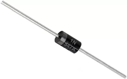
2. Large Signal Diode
The PN junction layer is thick on these diodes. Therefore, they are frequently used in rectification or converting AC to DC. The big PN Junction also boosts the diode's ability to carry forward current and reverse blocking voltage. Diodes with such a significant signal current aren't for use at high frequencies. The 1N4007 is a well-known diode of this kind.
These diodes are essential in a variety of Power Supply applications. Diodes with high reverse blocking resistance often have forward resistance values in the micro- to the mega-Ohm range. This high voltage and current capability make it suitable for electrical appliances designed to dampen excessively high peak voltages.
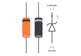
3. Zener Diode
It's a passive component that operates according to the "Zener Breakdown" theory. It was created for the first time by Clarence Zener in 1934, and in a forward bias condition, like a conventional diode, it permits current to pass.
However, the diode does not conduct under reverse bias conditions until the applied voltage approaches the Zener Breakdown voltage. It can guard against brief voltage pulses that could damage other semiconductor gadgets. It controls the voltage.
4. Light Emitting Diode (LED)
These diodes produce light energy by converting electrical energy. The initial production began in 1968. When placed in a forward bias, it emits light via an electroluminescence procedure whereby energy holes are converted to electrons.
LEDs were initially exceedingly expensive and mainly utilized in specialized applications. However, the price of LEDs has decreased dramatically over time. As a result, LEDs have replaced incandescent bulbs in almost every application where artificial light is required, including homes, workplaces, streets, cars, and smartphones.
5. Constant Current Diodes
People sometimes refer to it as a diode-connected transistor, current-regulating diode, or current-limiting diode. Diodes can control voltage at a specific current. Useful as a current restrictor with two connections, it. In this case, the JFET limits the amount of current so that the output impedance is high.
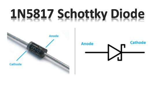
6. Schottky Diode
These diodes have a junction produced when you bring metal into contact with semiconductors. The forward voltage loss reduces to a minimum due to this. N-type silicon is the anode, whereas metals, including Chromium, Tungsten, and Platinum, are the cathodes.
The Schottky diode has a shorter switching time because of its metal junction's large current conducting capabilities. As a result, the Schottky diode is...