 pastcompute
System Overview & High Level Design
Description
Sentrifarm is comprised of a network of energy harvesting sensor nodes, geographically distributed according to the topology of the farm, able to run on low power, and communicate over extended distances without relying on the mobile phone network.
(This Project Details along with linked material presently constitutes the top level System Design Document required for the finals. Other entry criteria are listed in various project logs)
Novel features include intelligent back end monitoring and data analysis, a shield-like system allowing the SX1276 radio to be connected to completely different embedded boards, a custom design intelligent rain gauge, and the ability for long range farm monitoring of multiple paddocks without requiring multiple SIM cards.
Operational Concept & User Scenario
Refer to the Operational Concept Github.
Benefits to Farmers
- Timely information reporting
- Improved safety & immediate Grass Fire Danger Index visibility
- Improved knowledge of cropping
- Reduced operating costs
System Requirements
- Primary aim: immediate notification of conditions to farmer
- Secondary aim: log as much data as possible at the farm base, including from sensors/data not normally recorded by farmers, for analysis and new discoveries
- Long ranges (eventually exceeding 20 km / 12 miles ) to avoid telco fees
- Intelligent: farm base calculates if conditions preclude reaping
- Usability / UX: simple app (e.g. 6am alarm, RED for no good, GREEN for OK)
- Inexpensive, robust, maintainable commodity components: farmers have enough expensive firmware upgrades for tractors &c to deal with
- Can expand to share data with community / crowd sourced information web sites
- Sensor nodes must be self sufficient for power
- Provide ability for the farmer to "tap in" to local sensors via a mobile device when on site
- Sentrifarm is also an experiment, designed to test various combinations of equipment and data collection protocols on a real farm
Initial Prototype
In the true hacker spirit, for the initial hackaday prize build much of the equipment (in particular, the various computing modules used to build the nodes) has been chosen due to being on hand, we have more important things to spend money on at this time :-) however, the design is such that they can be changed easily to more 'production' oriented modules in the future.
Components include SX1276 915MHz LoRa radios, Teensy-LC and ESP8266 modules, ATtiny powered rain gauge & wind gauges, and Raspberry Pi nodes.
Architecture
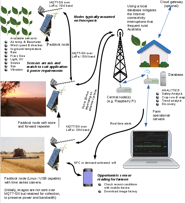
Sentrifarm supports a variety of nodes:- Farm base station - aggregates and forwards data from other nodes to databases and monitoring applications, using an industry standard protocol (MQTT)
- Paddock node - also called the Fencepost station, because the prototype nodes will be mounted on paddock fenceposts - a solar powered device with reasonable computing capability, able to record data from a wide variety of sensors including rain, wind, air temp, humidity, UV, frost, daylight and even advanced features such as imaging, security and equipment telemetry
- Ground sensor - designed for collecting in-ground temperature and moisture, potentially in a mesh across a paddock. Depending on the situation may be wired to a Paddock node, or preferably wireless and solar or piezoelectrically powered
Note that paddock in this context may be between 4 and 100 acres or potentially larger...
Sentrifarm will have a database and monitoring system, linked to the Farm base station node(s).
The Paddock Node includes a couple of different mode configurations:
- Repeater - will collect local sensor data and local ground station reports and also provide a store and forward for Leaf nodes and forward all data to a Farm base station
- Leaf - will collect local sensor data and local ground station reports and has a single point to point uplink to a Repeater
The point to point store and forward model has been chosen for the hackaday prize entry as this best suits the topology of the real working farm the system is being developed for. The implementation under way for the hackaday prize provides for the nodes and network topology to be upgraded in the future to use LoRa or Dash7 or another more scalable control system.
Remote communications use ISM band frequencies to mitigate licensing requirements.
The MQTT-SN protocol is used for communication between the Ground sensors, Paddock Nodes and the Farm Base station. This allows the various nodes to be asleep or discharged for periods of time, and simplifies interfacing to the radios. MQTT-SN bridges to MQTT on each of the Farm base station nodes.
Design Overview
The remote communication network utilises Semtech SX1276 LoRa radios (inAir9 modules) operating in the 915MHz ISM band. In Australia, this is limited to the range 915-928 MHZ. The SX1276 communicates via SPI. The hackaday prize build use BMP180 i2c barometer modules, DS18B20 1-wire temperature sensors, DHT-11 humidity sensors, wind pulse & and custom designed rain gauge, and a variety of other modules and sensors will be integrated over time.
The Farm base includes the following equipment:
- Standard computing equipment located in the farm office, with software including MQTT broker and docker container for logging and visualisation using Carbon and Grafana, other tools, initially accessed via web browser for maximum mobile device compatibility. Optionally we can replicate data to a VPS in the cloud.
- Farm station nodes. The intended hackaday prize build will use Raspberry Pi, providing two downlinks in different directions to suit the topology of the farm. Because the Farm station has access to power, the extra draw of a Raspberry Pi compared to other modules is not an issue. We are using one radio per Raspberry Pi to simplify the antenna design and software implementation of this initial build.
The first version of the Repeater Fencepost nodes are built using a Carambola2 embedded Linux device, with plans to build a version using the Domino.io openwrt board. This provides USB host functionality allowing easy local logging to USB storage for development and diagnostics, and the ability to add other USB devices for various purposes including audio visual and other experiments. The Repeater Fencepost will need a larger solar panel (and SLA battery) than the Leaf nodes but there will be less of them. Where data such as images is collected, this will not be transmitted over the radio due to power / bandwidth but instead collected onto SD card / USB. A novel feature is a button that will allow the farmer to drive up and turn on the wifi (normally off to save power) to download images to a mobile device.
In practice, we have presently deployed the farm sensor using Carambola2 instead of Raspberry Pi due to issues experienced with reliability.
The Raspberry Pi, Carambola2 and Domino.io all run OpenWRT.
Circuit diagram v0.1 of the carambola2-inAir9 shield at Github.
For the hackaday prize build there will be two types of leaf node:
- A build using the ESP-201 ESP8266 module
- A build using the ARM-powered Teensy-LC
This will allow the power usage of the Teensy to be compared with the ESP8266 in deep mode under real world solar powered conditions.
Both the Farm base, Repeater and leaf nodes are designed such that the electronic circuitry to the SX1276 radio is interchangeable regardless of whether the computing module is Linux capable or the aforementioned microcontrollers, using a shield system. Where possible a similar approach is applied to the software used for radio communications.
Circuit diagram v0.1 of the adaptor shield at Github.
The shield allows for a wide variety of sensors to be integrated on demand, by providing i2c, 1-wire and a PCF8591 i2c 4-channel ADC.
The ground station design is still under review, however the aim is for it to be similar in shape to a solar powered garden LED light, except pushed into the ground.
The custom designed rain gauge will use a small form factor arduino compatible, either an ATMEL ATtiny85 like a digispark or a beetle, or an Arduino Nano, or if time permits a custom board based on the same. The intent of the custom design is to gain a greater level of accuracy for a lower cost than easily available on the market.
For reading wind pulses without requiring the sensor nodes to be continually powered, an ATtiny85 (in the form of a digispark) acts as an i2c slave. Code is located on github separately at https://github.com/pastcompute/Pulse_i2c_slave