 Jon Buford
PART 1 (What is the HAT spec?)
Raspberry Pi HAT modules are a great open standard for adding functionality to a Pi that either needs additional hardware, or a better way to connect with the rest of the world. The Pi Foundation has a pretty good spec for what is needed to make a board officially HAT compatible, but it takes a little bit of reading and parsing. This page on the design guidelines has all of the specifics of what you need to consider when designing your HAT.
From the main page:
A board can only be called a HAT if:
It conforms to the basic add-on board requirements
It has a valid ID EEPROM (including vendor info, GPIO map and valid device tree information).
It has a full size 40W GPIO connector.
It follows the HAT mechanical specification
It uses a GPIO connector that spaces the HAT between 10mm and 12mm from the Pi (i.e. uses spacers between 10mm and 12mm).
If back powering via the GPIO connector the HAT must be able to supply a minimum of 1.3A continuously to the Pi (but ability to supply 2A continuously recommended).
Other details you need to know:
- There are specific GPIO sequencing that you need to be mindful of. By default, some pins are active at boot, so that can have unexpected results if there is no current limiting on whatever is connected to them.
- On pins 27 and 28, do not connect anything other than an EEPROM that is to the defined spec. You can leave off the EEPROM, but that is no longer officially a HAT. As long as you don't connect anything to those pins, the Pi Foundation would still probably be supportive, but you can't say it is a HAT.
- If you are back powering the Pi via the HAT, you need to not connect the 3.3V supply from the HAT to the Pi, and you need to put in protective components to prevent 5V via USB causing conflicting power issues.
So, that seems to be the lot of it, the Pi Foundation really tried to leave the rest as wide open as possible to let you be as clever as you want.
PART 2 (OK, so how do you design a HAT?)
Well, knowing the basics of what things you need to call your design a HAT is only a small part of it. The best resource I found for the details of what each pin is capable of is https://pinout.xyz/ If you check their GitHub you can find good resource files with all the functions defined in YAML format. Here is a good image based version of the same info.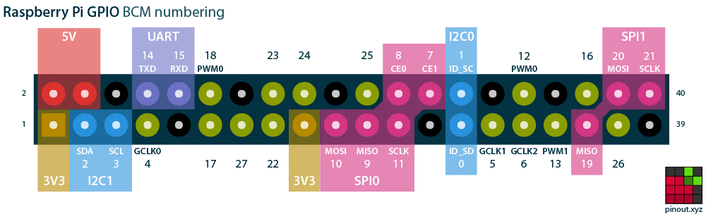 I know everyone may have their own way to approach this part of the design. Some people might start with a schematic with all the bits and then just start making connections, but what I have found is that doing this in a spreadsheet helps to both make it easier to parse all the options and to do some checking to see what is available and if the function you assigned to a particular pin is valid. You can find a spreadsheet version of this pinout in this project files here.
After some consideration, the final system level design is to use the Raspberry Pi 40-pin header to interface to a small MCU that is directly controlling 2 IO modules. The size of the official HAT hardware makes it pretty much a requirement for the IO module connectors to be mounted directly on it instead of making it an adapter to the Controller slot on our backplanes.
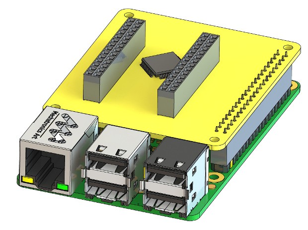
This arrangement lends itself to making two different versions of the HAT. One with a Power module connector and one designed to be powered by the HAT connector. The design with the Power module will require some additional components to prevent power conflicts if powering the Pi from the HAT.
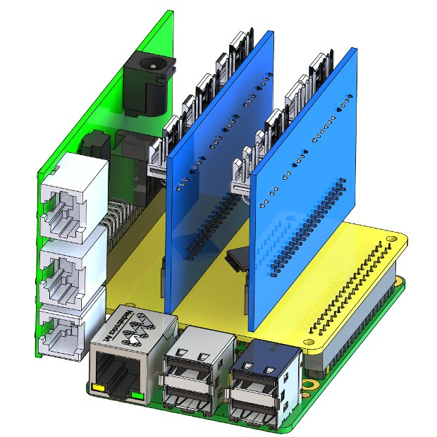
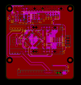
As shown here, the larger version lends itself to things like POE installations well, but it would be equally well suited for a robot or 3D printer.
OK, so we have the form factor, the placement of the connectors and an idea of where to place the MCU in the layout.

That gives us the major components and systems that need to be put into the schematic. In order to get the net connections (the labels you see shown on the pins that indicate what connects to what), I use a spreadsheet for the big things. At this point, if you are using KiCAD, you can download the template for the HAT spec to seed the schematic and board design.
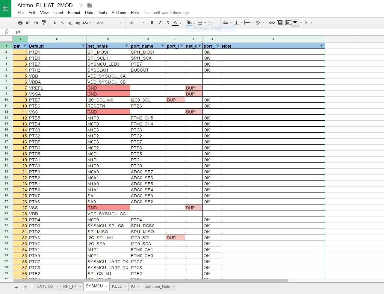
I've shared this spreadsheet in the project as a live link, so you can see the details on how I have created the interconnections. The log entries have more details on these types of steps.
I go back and forth a bit between the spreadsheet and the schematic, importing changes and putting in the other components supporting the system design. Once you are satisfied with the schematic, you move onto the PCB layout and the fun begins. I'm assuming you either know how to do PCB layout or will follow a more detailed project that is focused on this, but I'll walk through the designs I wound up with and the specific things that will be common to other designs.
The parts that are going to be common to any HAT design is the EEPROM and the power handling between the HAT connector and the rest of the board. The EEPROM, it is pretty simple and there isn't much to consider other than the placement in this case. If you want your design to be HAT compatible, it must have this. The power is a bit more dependent on your application.
In this design and in the template, I've included the recommended components for preventing issues with a Pi powered by the HAT from having power conflicts on the 5V when the USB is plugged in. In addition, I've put in some jumpers that allow for configuring the 5V and 3.3V power to connect directly to the HAT pins and for selecting the MCU power supply voltage. It may be desired for some applications to run the KE02 MCU at the 5V level. Keep in mind this may damage the Pi if you connect it in this configuration.
So, you need to plan out how your power will work, if it is coming from the HAT and if it is coming from the HAT, are you supplying 3.3V and 5V to the HAT directly, or are you only doing 5V and then drawing 3.3V from the Pi's supply.
Getting Slotty
What isn't shown in the designs above or in the provided templates are the slot and cutout for the camera and display ribbon connectors. These are optional and will depend completely on your design. Also, different PCB manufacturers may have very specific things they can and can't do, so I figured this is OK to leave it up to you to decide what you need for your HAT.
Putting the Program in EEPROM
There are a few sources for creating what gets put into the EEPROM.
Howto: Raspi HAT EEPROM and device-tree
For this, you just need to follow the documentation and what this ends up looking like will vary a lot depending on your design. For my design, I'll create a base program and EEPROM contents that make the HAT as a basic IO extender, but I would expect many users to customize their MCU program and will need a new EEPROM to match it. That is why I put in a write jumper for the EEPROM. You may not need this functionality or may be able to trim down the jumper to either a solder bridge/resistor or a pin header where I have put both.
OK, that is about it for this project, after this, it really is just testing and programming the board just like any MCU design.
I hope this has been helpful, please let me know if you see any design issues or if you have questions on specific things that I might need to make more clear.