 Tyler
TylerAfter the many hours that went into the initial hardware design, it became clear there was more work to be done. What followed was several weeks of contemplation, reflection, and mourning, but then it was time to suck it up and try again with a new approach: a vacuum system. (pun intended if you couldn't tell.. I'm guessing you could tell... I hope you could tell....)
The vacuum idea was different than most drink machines I've seen others make. It would address the problems from our initial design, but there were new challenges that needed to be addressed, mainly with how to plumb the system. Keeping in mind goals for the system to be reasonably low-cost, and simple, yet functional and compact led to the following design:
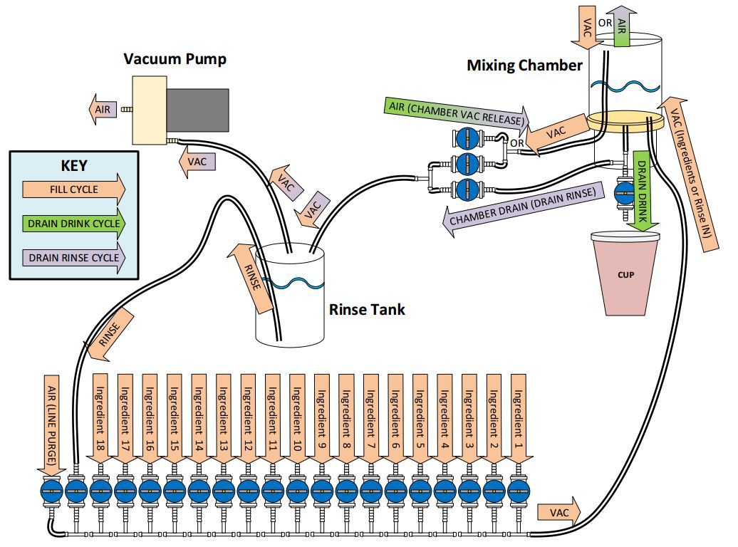 To pour a drink, there are essentially 4 steps, using 3 different flows or "cycles". These cycles are identified in the diagram as the "Fill Cycle", "Drain Drink Cycle", and "Drain Rinse Cycle". The different cycles represent different states of the blue solenoid valves, creating different flows in the system. To elaborate, let me walk you through a complete drink pouring process.
Step 1a: (Fill Cycle)
In the Fill Cycle, arrows having a light orange color indicate the flow. (Arrows with two colors apply to two different cycles.) To start the process, the vacuum pump turns on, and the valve connected between the rinse tank and the hose extending to the top of the mixing chamber opens. This creates a vacuum inside the mixing chamber. Notice that the vacuum hoses from and to the rinse tank do not extend down into the rinse solution. The rinse tank is a solid sealed container, so the vacuum created in the rinse container is also created in the mixing chamber. With the vacuum established, the individual ingredient valves can be opened to bring the ingredient from the bottle into the mixing chamber. The ingredient valves are opened one at a time, and timed according to a calibration factor to retrieve the appropriate amount.
Step 1b: (Line Purge)
After the ingredients have been sucked into the mixing chamber, there is still some liquid remaining in the line. To make sure it is included in the mix, the line is purged by opening the AIR (Line Purge) valve at the end of the ingredients valve array. A side-effect of this is that the air purging the line bubbles up through the mixture in the mixing chamber, effectively mixing the ingredients. Once the line is purged, the valves are closed and the vacuum pump is shut off.
Step 2: (Drain Drink Cycle)
The Drain Drink Cycle is fairly simple. In this cycle, the DRAIN DRINK valve opens at the bottom of the mixing chamber, and the AIR (Chamber Vac Release) valve opens, releasing the vacuum in the chamber and allowing the mixed solution to dispense into a cup. After a timed amount, the valves then close.
Step 3: (Rinse - Fill Cycle)
At this point, the consumer is happy and has left the drink machine. You might be thinking... "Like, ewww now the next person will get any leftover liquid in the mixing chamber contaminating their drink." This is a downfall to this vacuum system approach. The solution, is the rinse cycle. This step is the same as Step 1, but instead of ingredient valves opening, only the RINSE valve, second to last in the ingredient valve array, will open. This will flush the line and fill up the chamber. Then, the line will again purge like in Step 1b, and the air-bubbles will help agitate the rinse in the mixing chamber.
Step 4: (Drain Rinse Cycle)
Finally, the last thing to do is empty the rinse solution from the mixing chamber, but we don't want to simply spit this stuff out of the drink faucet! In the Drain Rinse Cycle, the vacuum pump activates, but instead of the vacuum being routed to the top of the mixing chamber, the CHAMBER DRAIN (DRAIN RINSE) valve opens, along with the AIR (CHAMBER VAC RELEASE) valve. In this way, the rinse solution in the mixing chamber is vacuumed back into the rinse chamber for re-use. Now, obviously there may still be some drops of rinse solution that remain in the chamber, but this seems to be more acceptable than a sticky, strong tasting liquid. If water is the rinse solution, then the drink would be less contaminated than the effect from adding ice. It should also be noted that the mixing chamber is an easily removable container (in our case a Mason jar) for further periodic cleaning. The rinse tank is also removable so that the solution can be renewed. Now that we've talked about the plumbing system, let's look at what's controlling all of this.
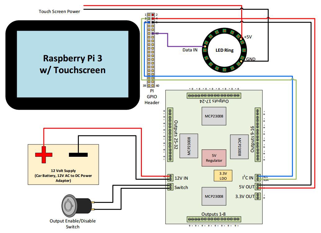
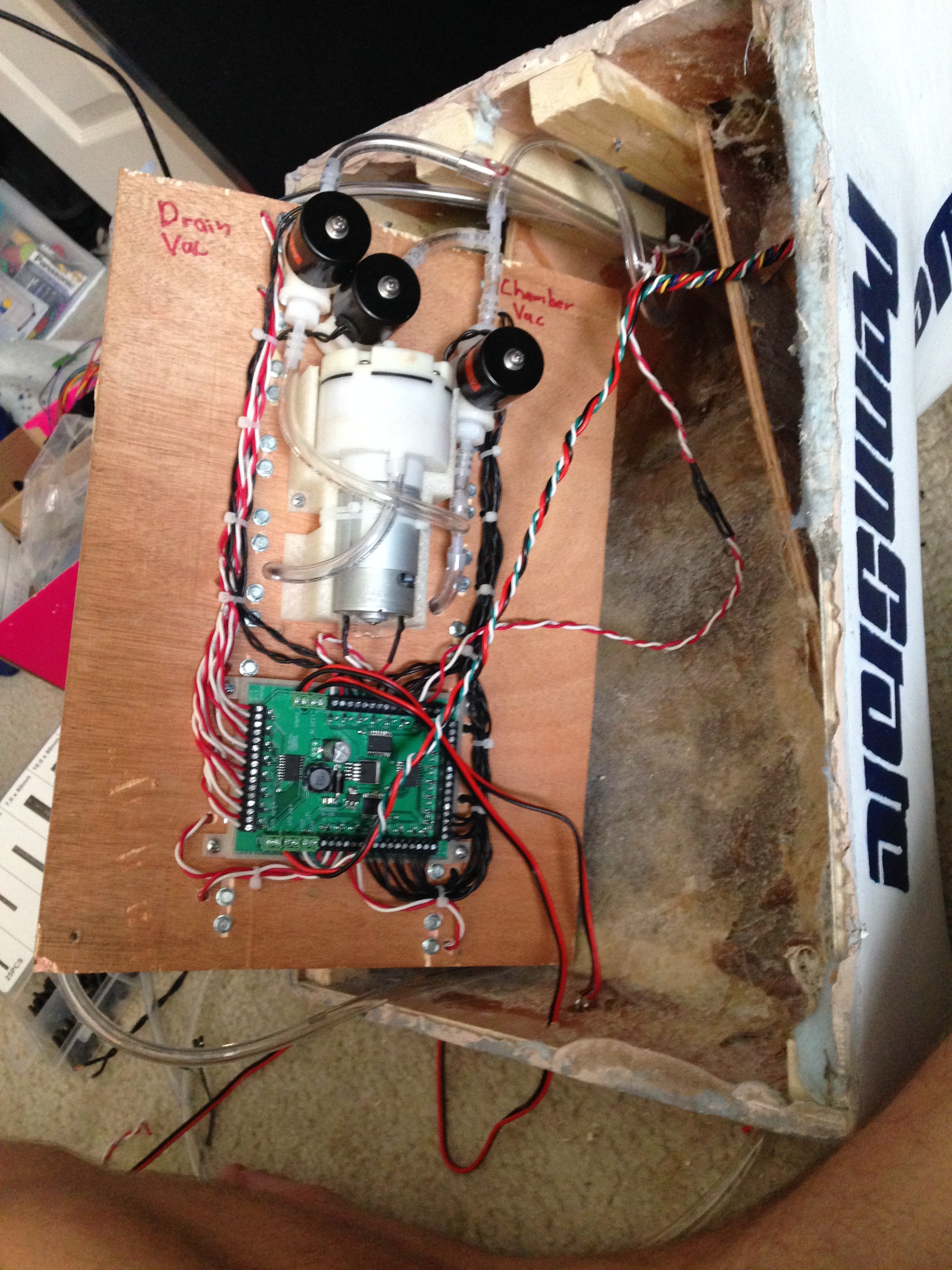
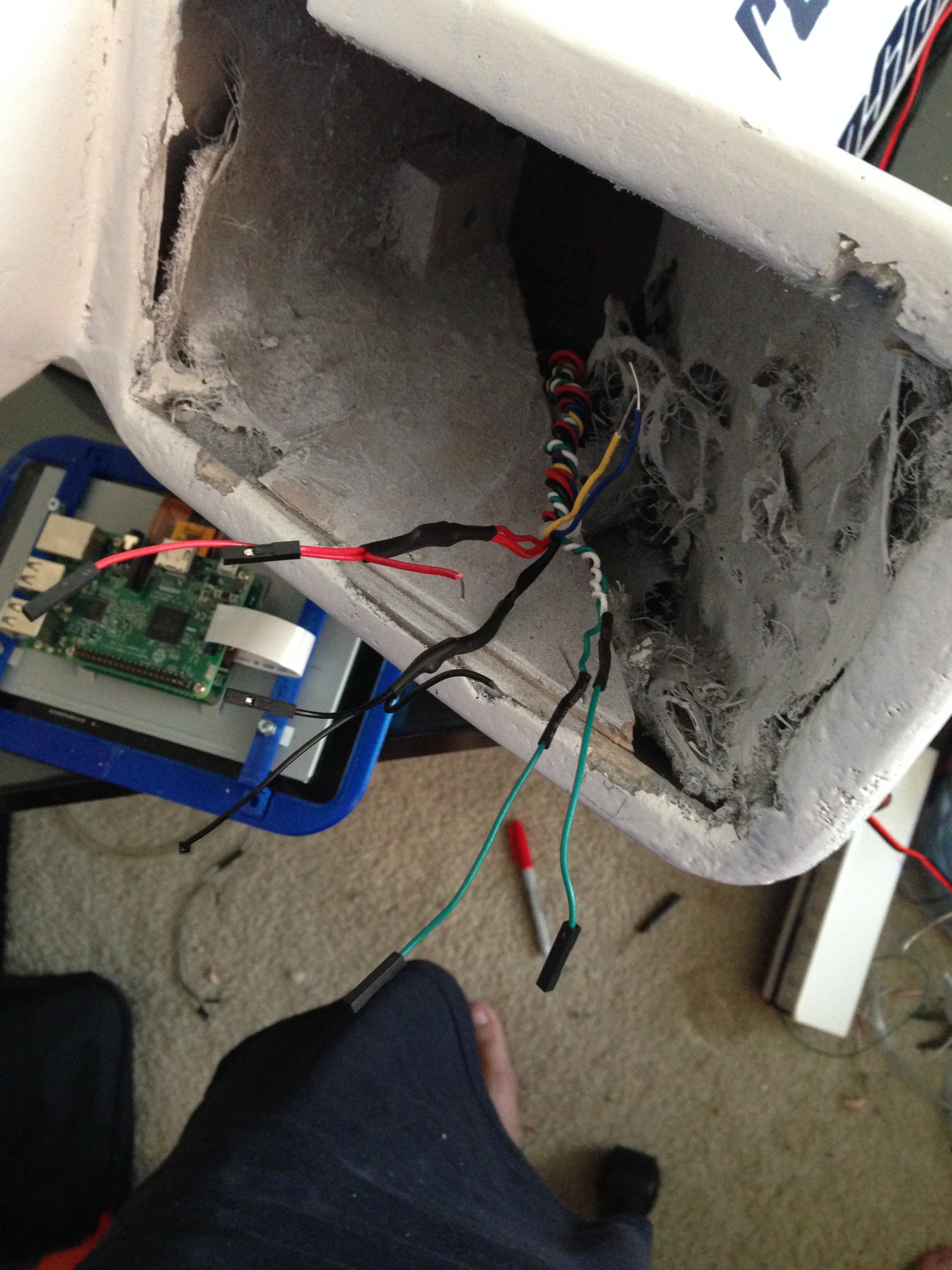
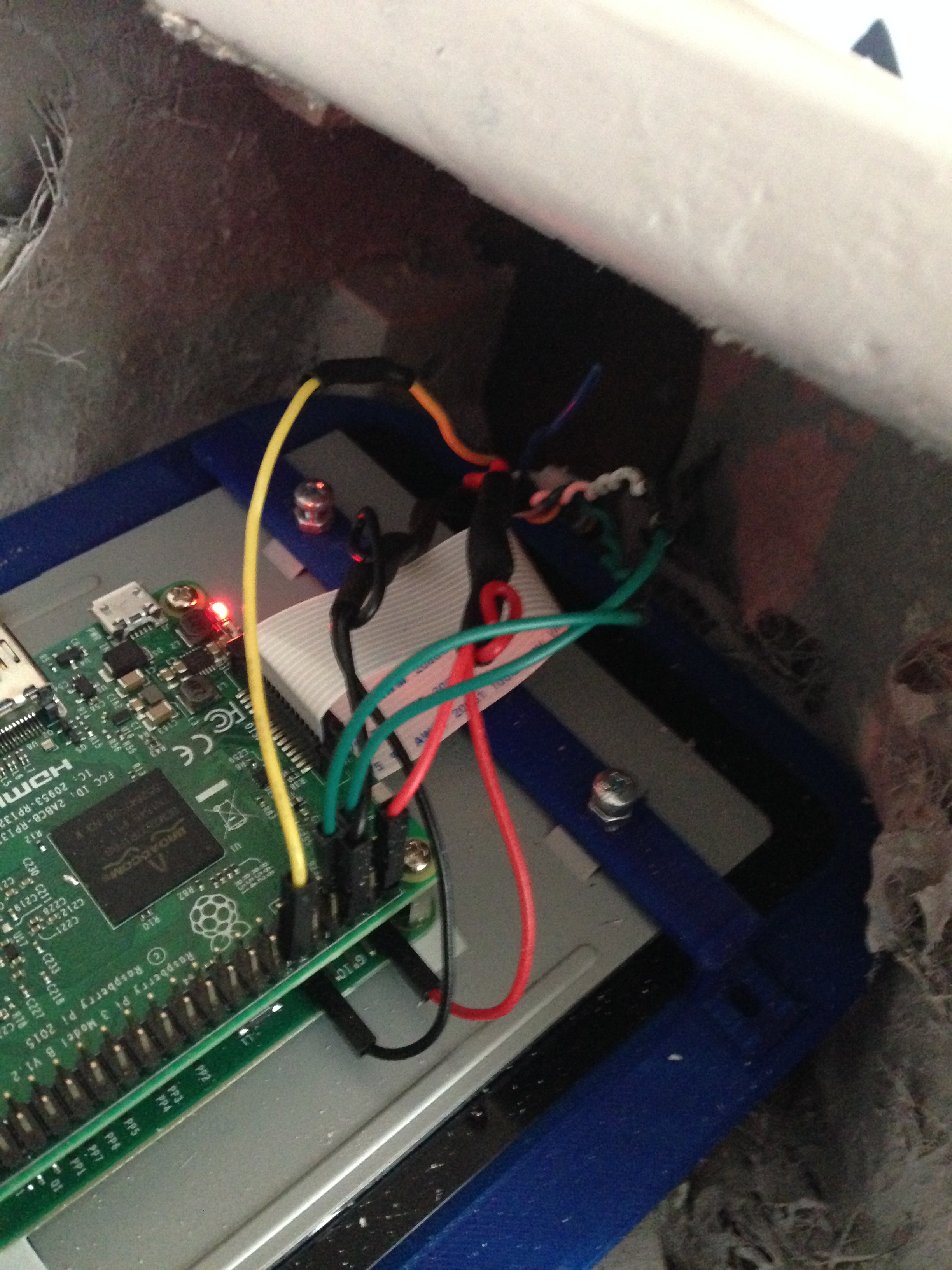
Since we wanted this to be a community project, we wanted to try and use familiar hardware. To have a capable system with several valves for ingredients, it was also necessary to have many GPIO. The best solution we came up with was to implement the GUI software and hardware control software on a Raspberry Pi 3. The Raspberry Pi 3 was paired with the standard Raspberry Pi 7" touchscreen to provide the user interface. To connect the valves and pump, we developed our own PCB utilizing MCP23008 I2C GPIO expanders connected to some Power MOSFETs. This PCB is powered by 12V for the pump and valves, but also provides a switching power regulator to provide 5V to the Pi. The schematic and Gerber files for this board can be found on the project GitHub page at https://github.com/theopenbar/PCB. The design was generated using KiCad. On GitHub, you will also find the Python hardware control program for the Raspberry Pi 3 at https://github.com/theopenbar/Controller.
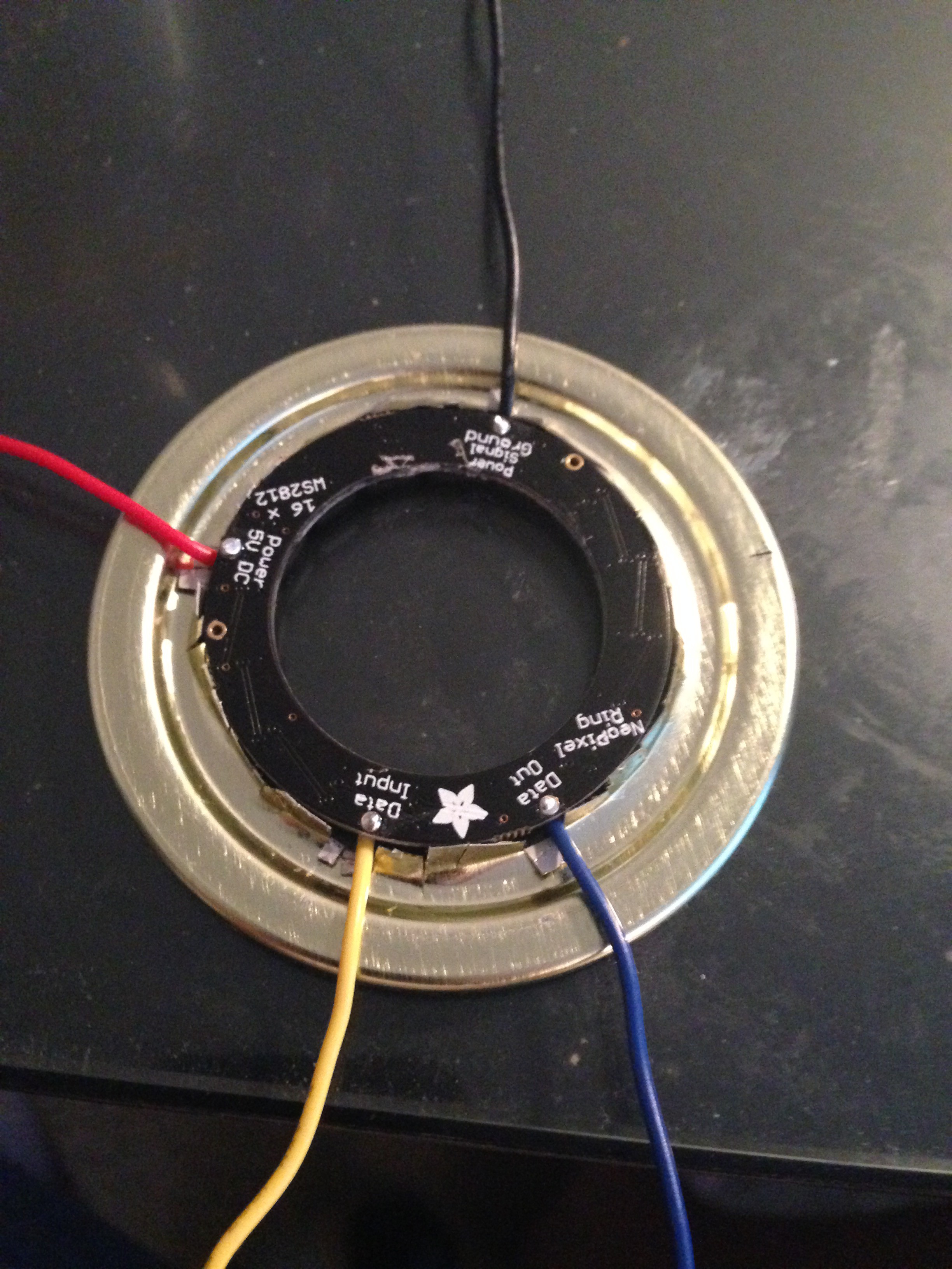
Another (optional) hardware piece we added to the system was a NeoPixel LED ring. These can be found on Adafruit here: https://www.adafruit.com/products/1463. We implemented the ring into the mixing chamber for some cool lighting effects during operation. Here is a simple wiring diagram of the system:
After watching some YouTube videos on people making various things from fiberglass, like boats and custom sub-woofer enclosures, I really wanted to try my hand at fiber-glassing. So for my implementation of The Open Bar, this is the route I took. Eventually, we're going to make detailed videos of a complete build, hopefully with a complete BOM and measurements. For now, here's a brief pictorial of my work constructing The Open Bar. This build was to prove the concept and sort out any bugs:
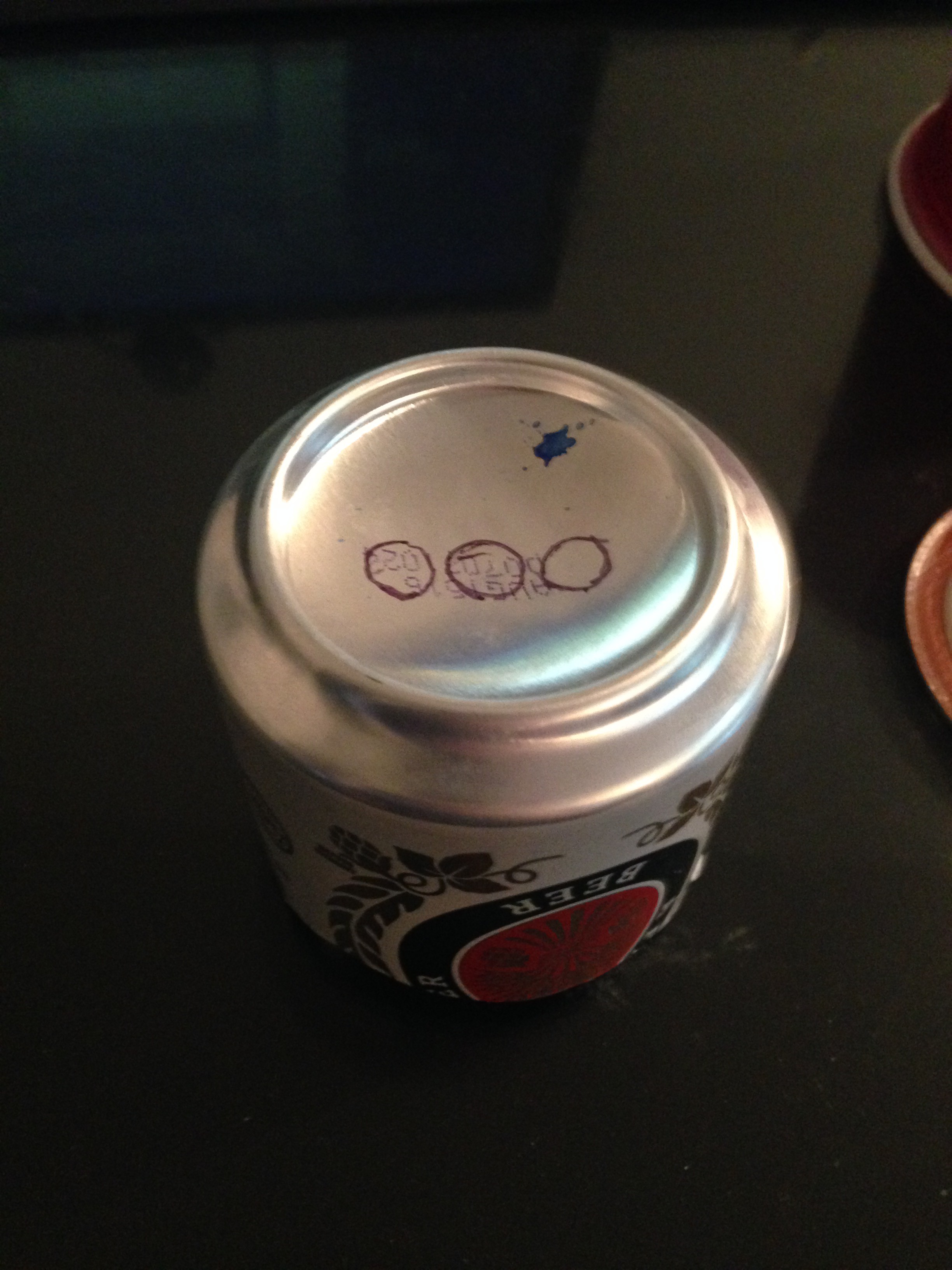
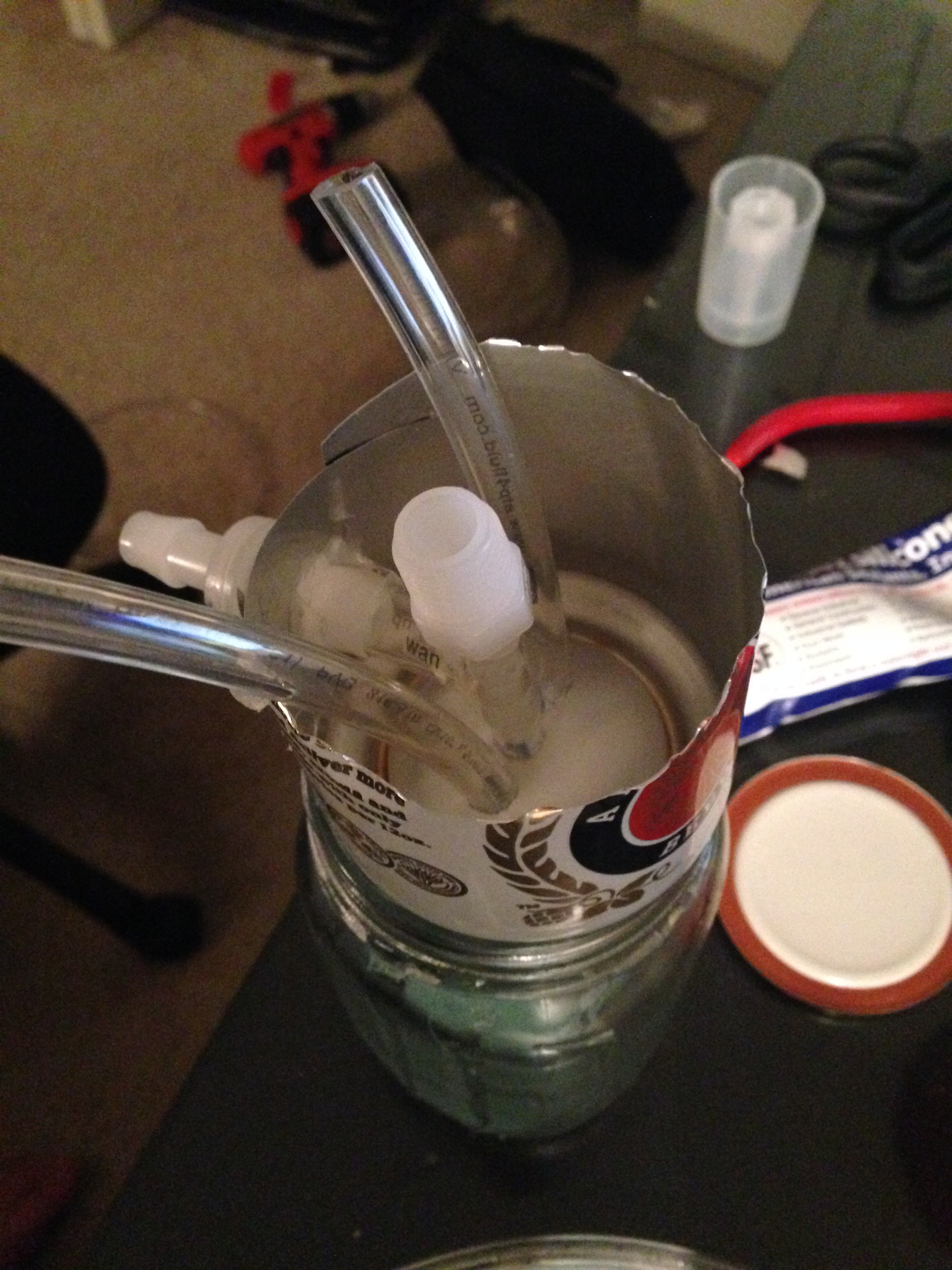
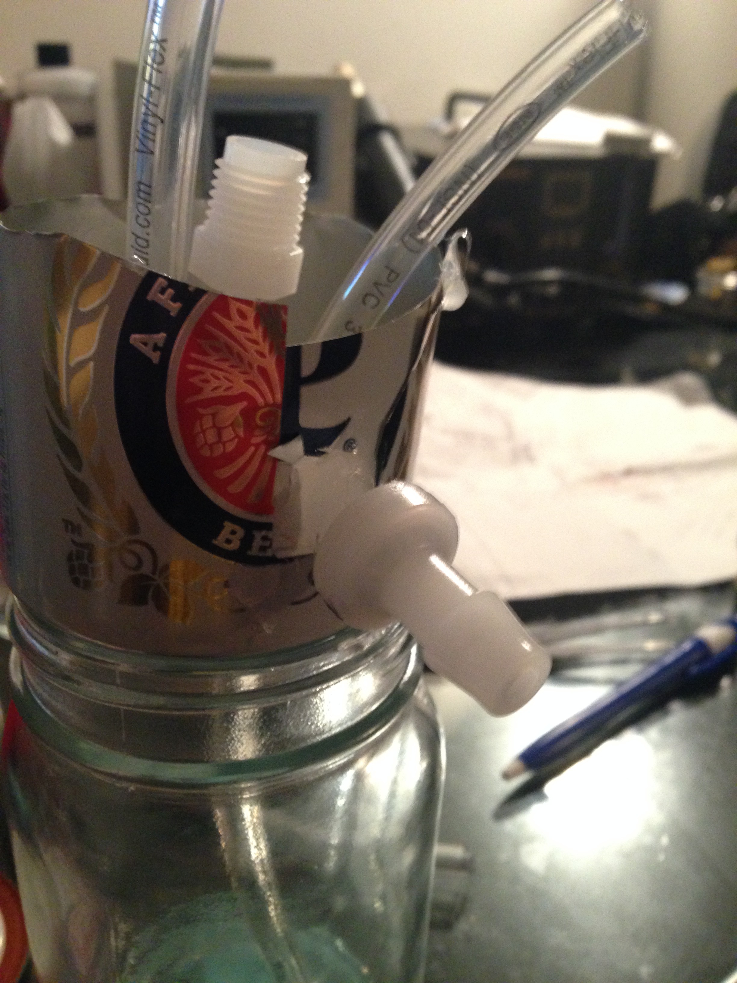
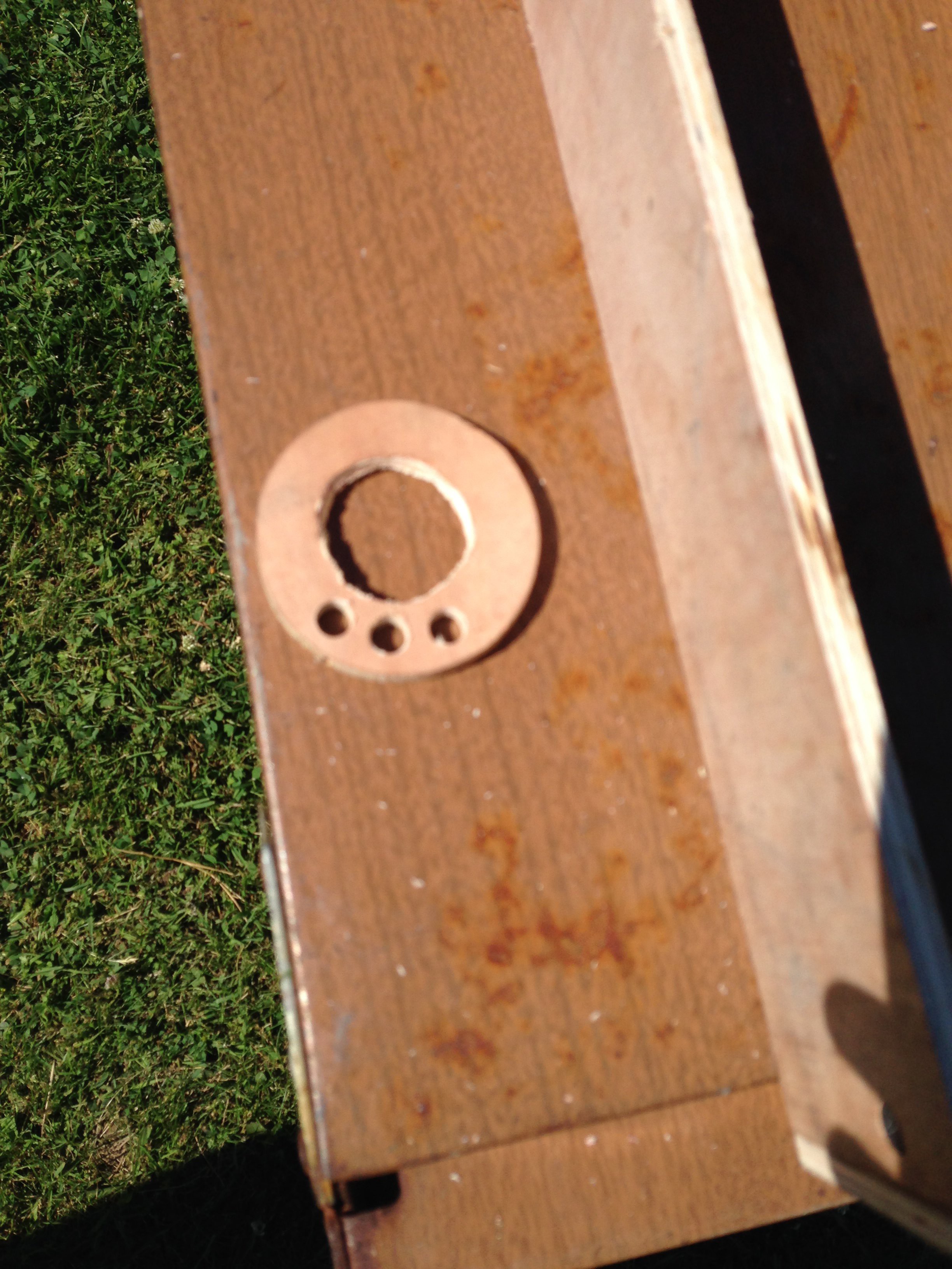
This is molding the first part of the mixing chamber base. It was molded inside an aluminum can with a hard-setting food-safe acrylic. It is upside-down in the above and below picture. The slight bowl in the bottom of the can will help to drain the chamber to the center drain hole. The drain valve will attach to the center NPT fitting. The two hoses are for the incoming ingredients and the vacuum connection. The other plastic fitting going out the side is a check-valve on the connection to drain rinse from the chamber. In the finalized design I decided to use a valve there instead. The Mason jar is just used as a support here.
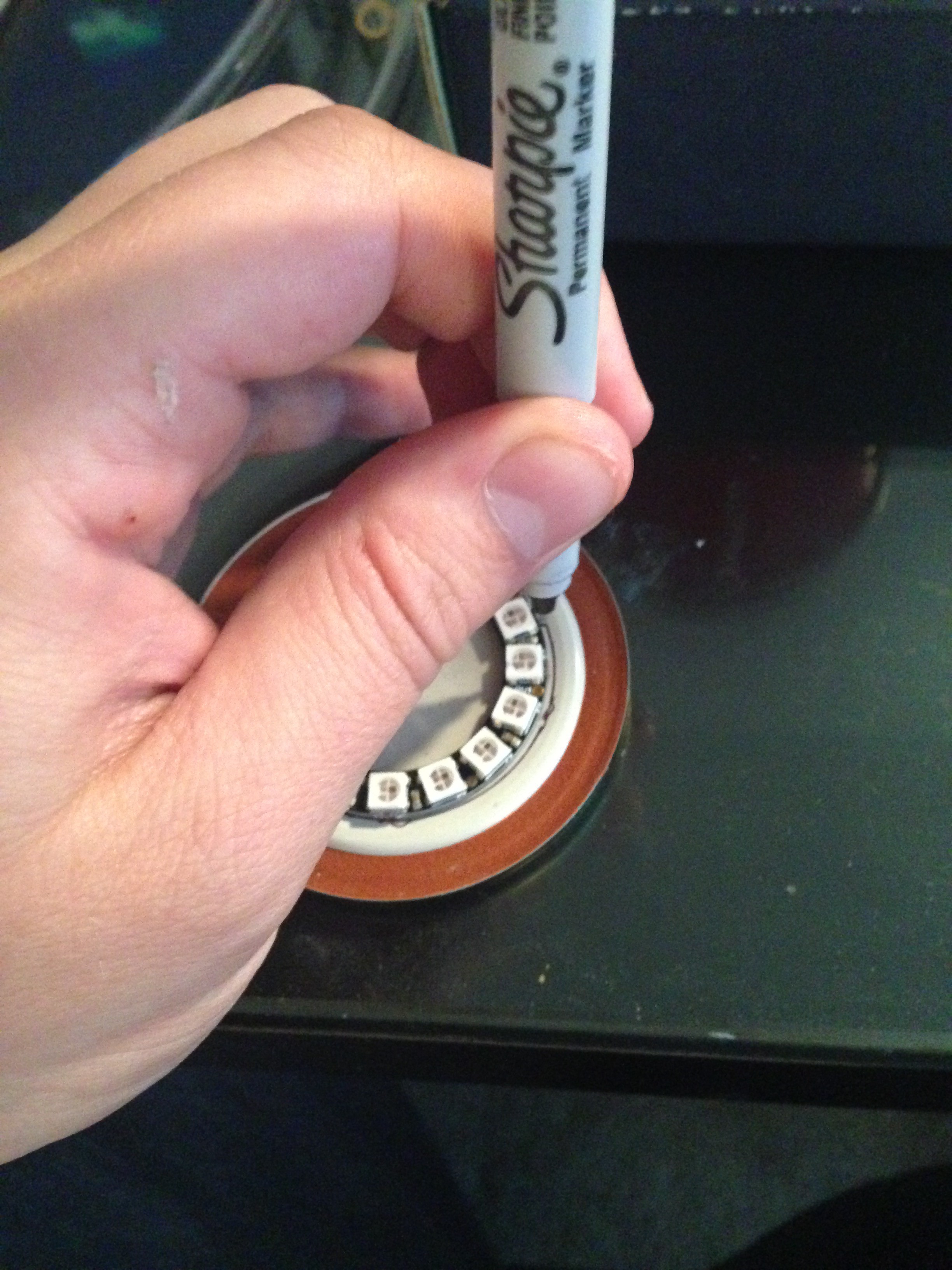
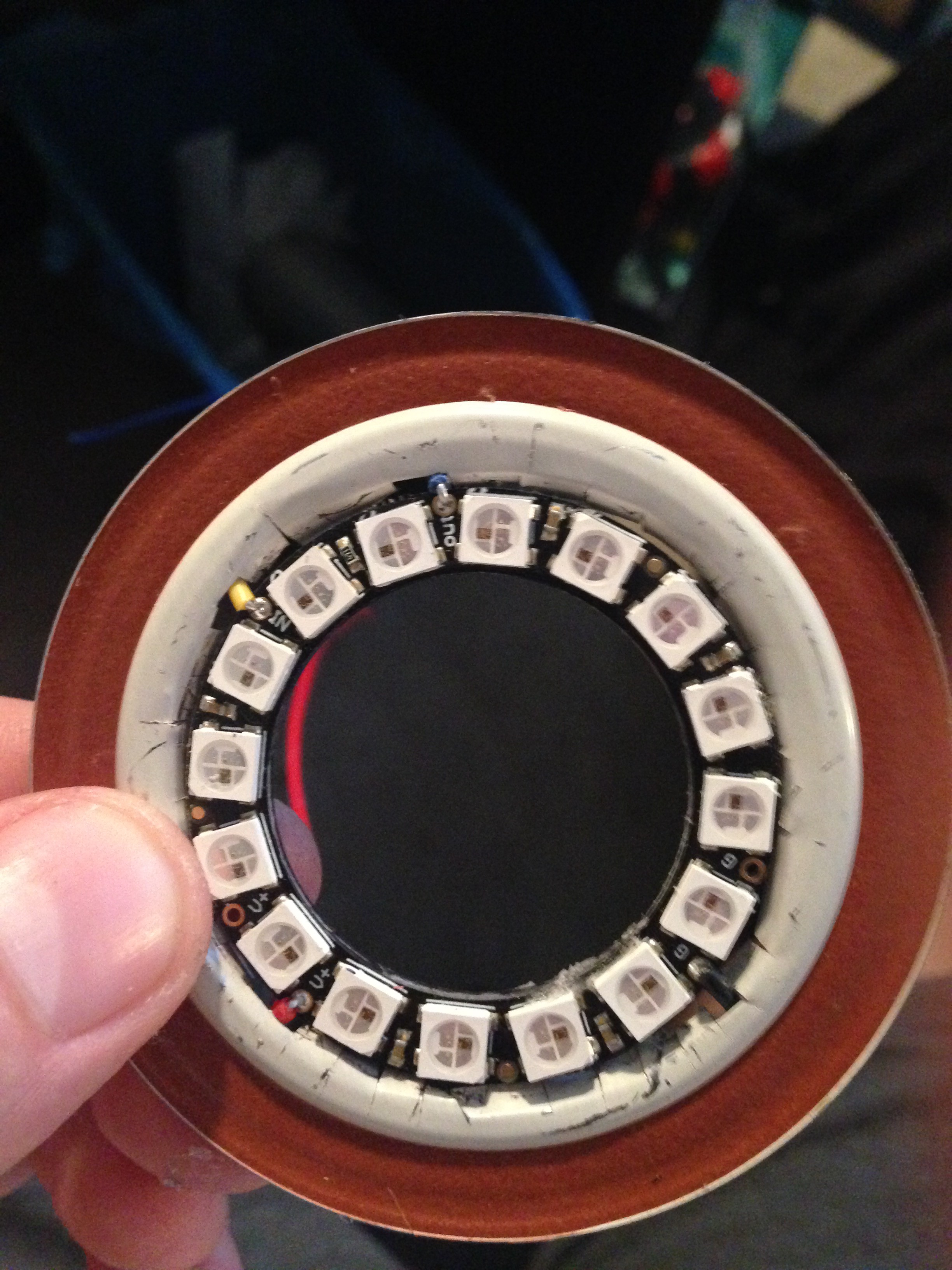
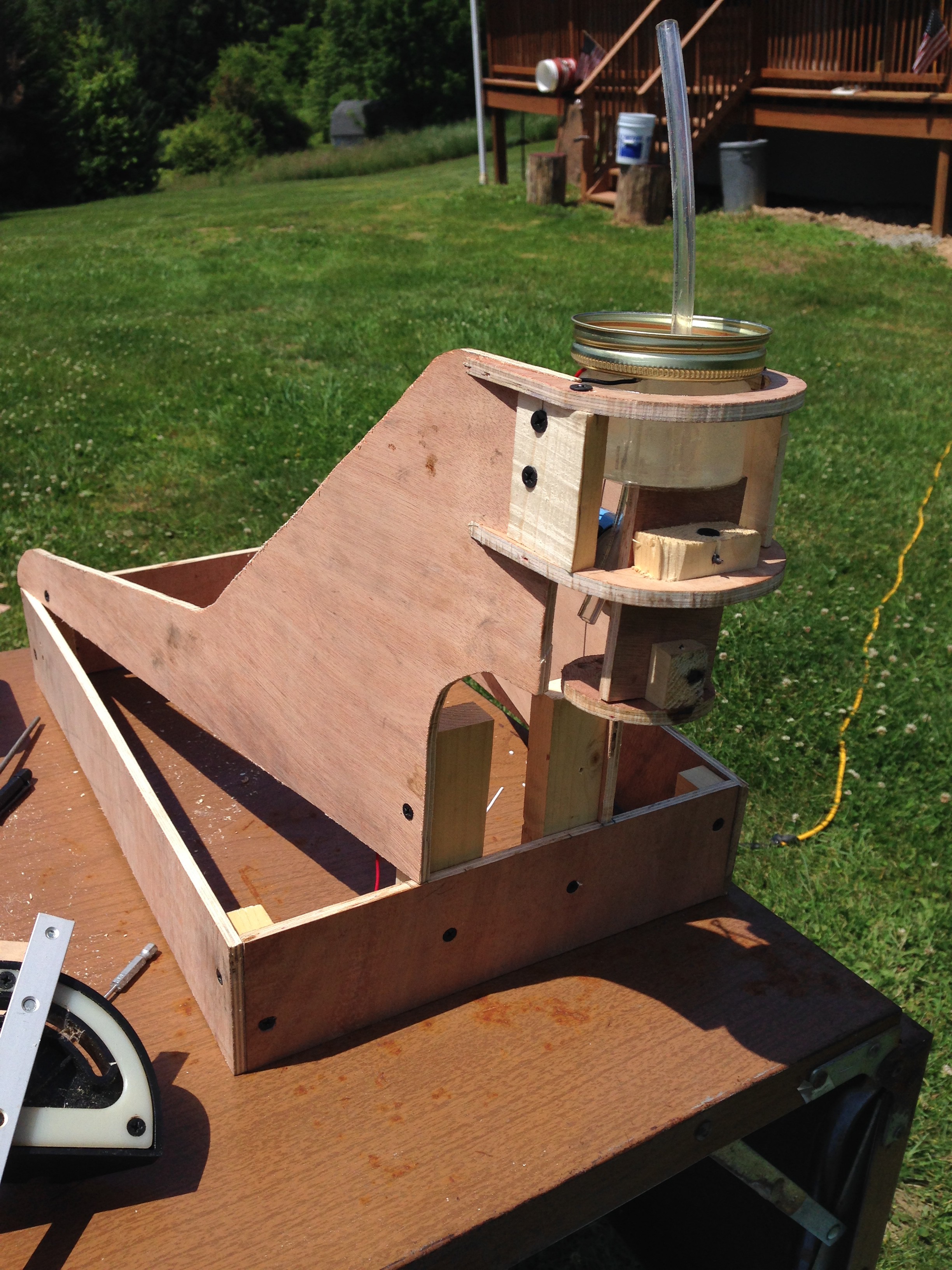
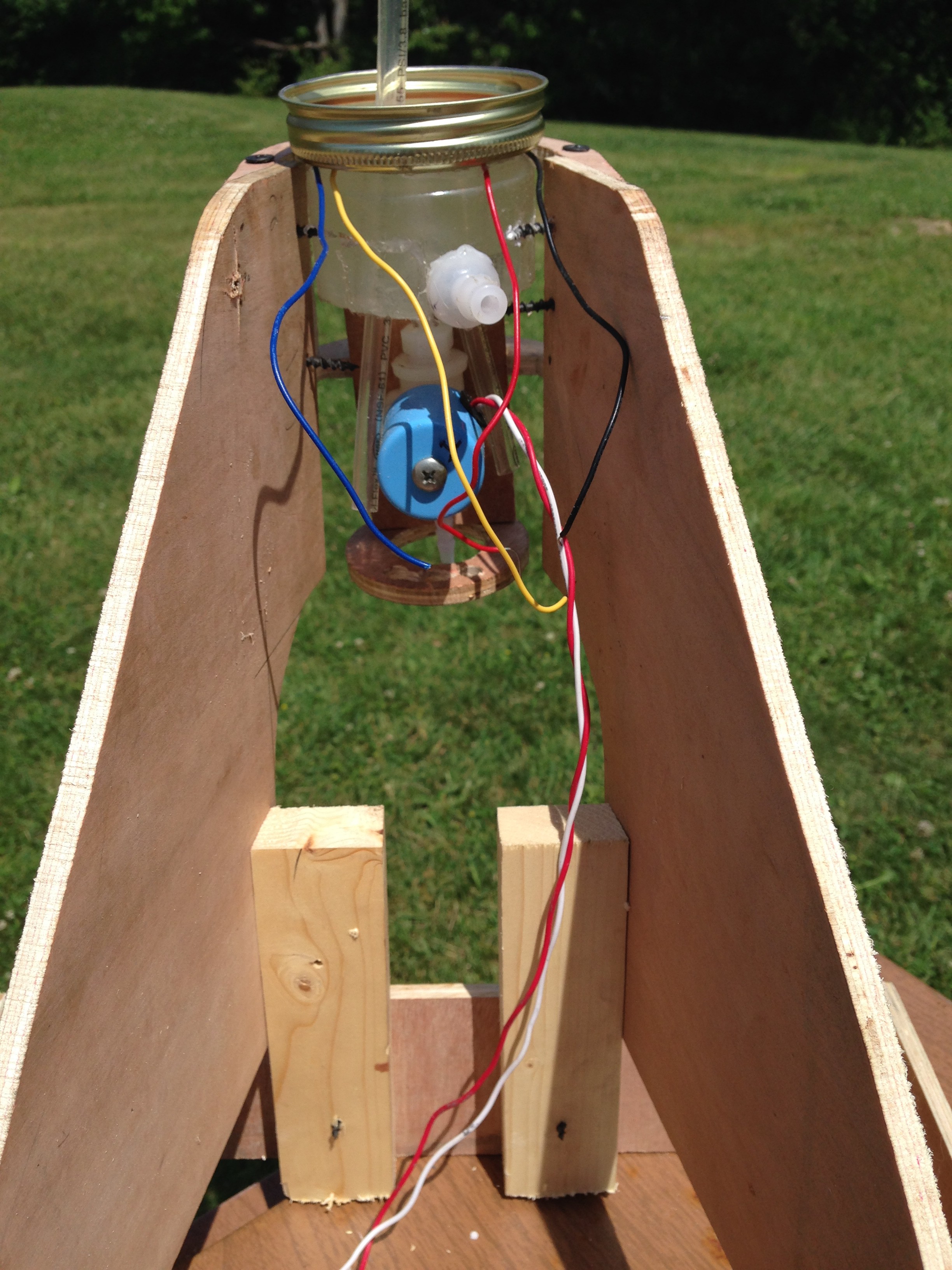
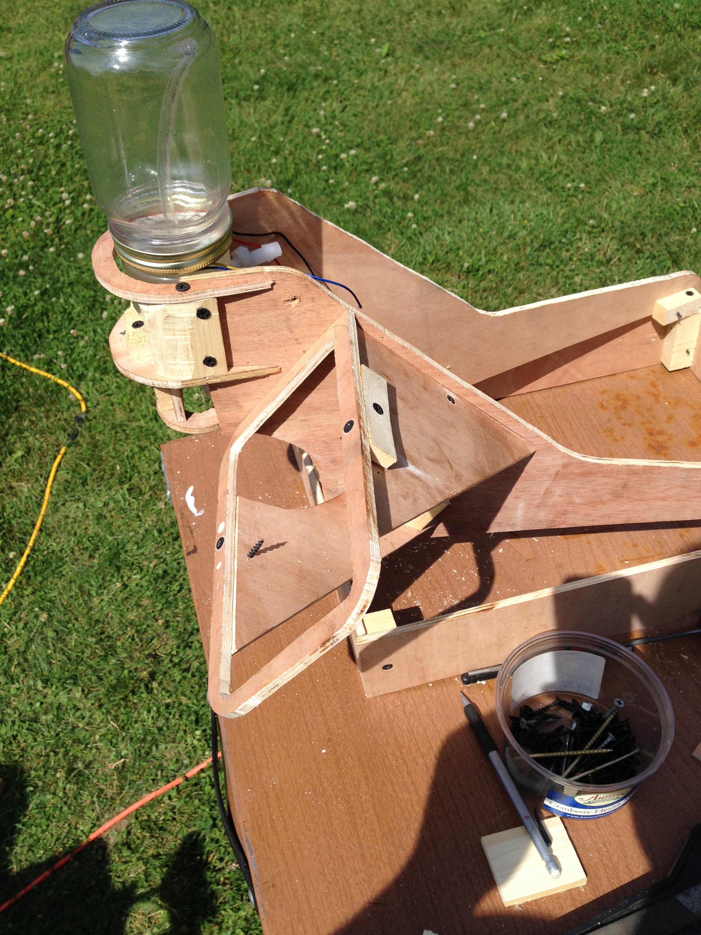
The NeoPixel Ring was placed inside a Mason jar lid. Food-safe silicon was placed around the lid and then set on top of the previous formed mixing chamber base. Then as show below, a cylinder formed from another piece of aluminum can was placed within the ring. The bottom of the cylinder had silicon around it to seal the base. This is to form a cylindrical riser from the bowl formed by the bottom of the aluminum can. I then poured more food-safe acrylic over the NeoPixel Ring to seal it and form it to the first part of the mixing chamber base. (Sorry I don't have more pictures of this. When we make another machine, we will make videos and be as detailed as possible.)
The above picture show the second part of the mixing chamber base consisting of the Mason jar lid, being formed on top of the first acrylic part. The clear food-safe acrylic covers the NeoPixel Ring from the inside part of the red rubber seal of the Mason jar lid, and the space in-between the aluminum cylinder and underneath the NeoPixel Ring. After the acrylic sets, the aluminum cylinder is removed, revealing a cylindrical cavity joined to the bowl shape of the first (bottom) piece of the mixing chamber base. The hose inside the cylinder is the vacuum hose that extends to the top of the mixing chamber. Again the Mason jar is just for support here.


 I tried to minimize 3D printed components so that they weren't necessary. I did cheat a little, but this just leaves some room for others to contribute ideas and get creative. For those that attempt this and do have a 3D printer accessible, I posted my 3D files on Thingiverse here: http://www.thingiverse.com/tylerh127/designs.
Discussions
Become a Hackaday.io Member
Create an account to leave a comment. Already have an account? Log In.