Before I even knew the slightest thing about inductors, capacitors, and any sort of circuit, I had picked out these crossovers from basic internet research. It has been pretty cool to be able to learn the physics of the crossover, finally understanding on a deep level how they work. I will try to give a brief overview of the physics of crossovers without confusing myself or others. A quick disclaimer: I do not have audio engineering experience, or actual engineering experience of any kind, just knowledge from projects, the internet, and my physics class.
The input
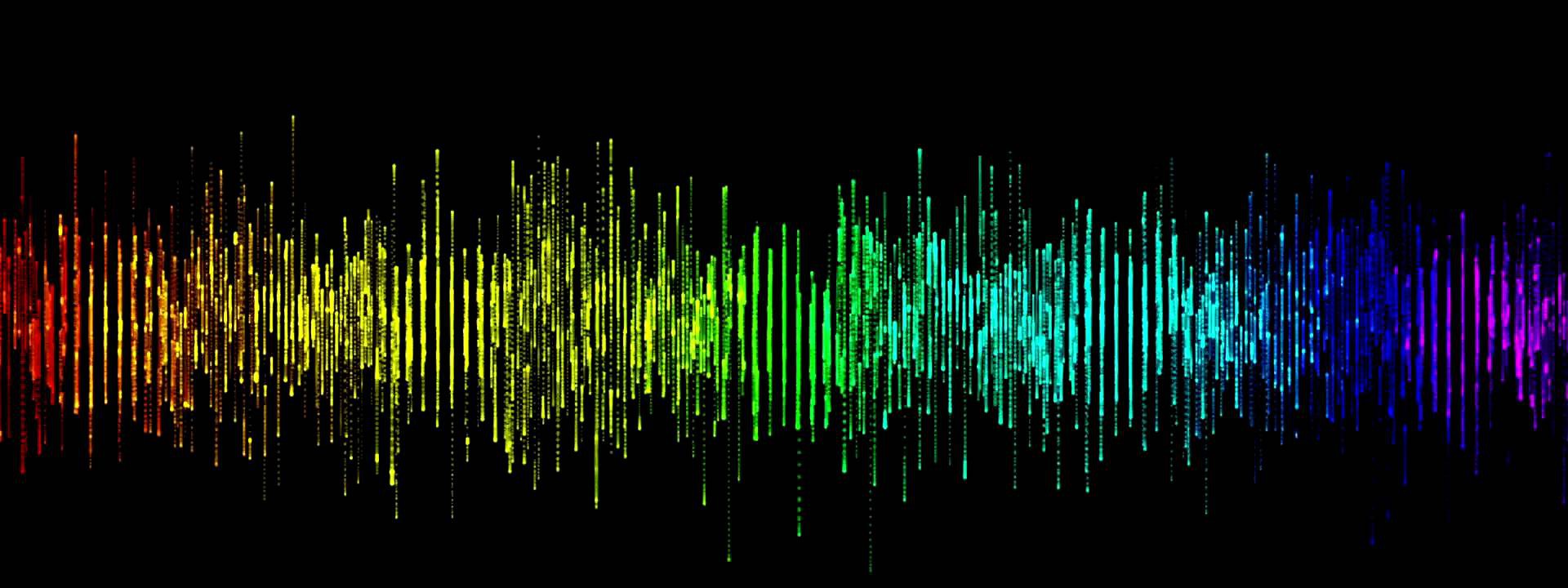
So a fundamental part of any speaker system is the input, where that comes from, auxiliary cord, Bluetooth dongle, it doesn't matter, but we know it has to be a form of AC current. The actual audio entering the system is in the form of a sinusoidal wave, which has different frequencies (highs and lows) and amplitudes (relative volume) in order to form sounds and thus a song. An example of such a waveform is shown below (An excerpt of Airplanes by B.O.B on youtube).
The crossover
I should state clearly what a crossover does: it separates an audio waveform (sinusoidal wave, AC current essentially) into 2 or more distinct waveforms that have different frequencies. Thus, in speaker systems, crossovers are used to separate a single input waveform into multiple waveforms to send to different speaker types. This results in an overall increase in sound quality as the speaker can be purpose built (think tweeters high frequencies, woofers mid frequencies, and subwoofers low frequencies) and spend all of their time creating sound at frequencies they are good at creating. A single woofer will attempt to create sound for the entire frequency range that it is inputted, which can range from around 25Hz to 20kHz (around the limits of human hearing).
My setup
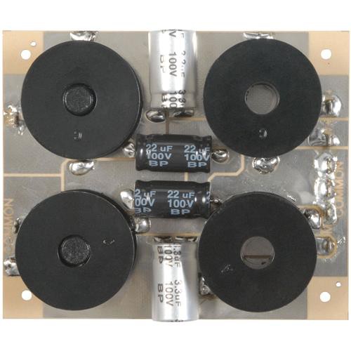
So this waveform enters the speaker system and enters either 1) a crossover or 2) an amplifier. In my project, I decided to use passive crossovers (not powered, less flexibility in tuning, but much cheaper and easier to connect) after the amplifier, to avoid needing multiple amplifiers after the crossovers. This means the waveform enters the amplifier, and the amplitude of the sinusoidal wave is increased many times the amplitude of the input wave, depending on the power rating of the amplifier and the volume the input and amplifier are set at. Volume is directly proportional to maximum amplitude, which is directly proportional to the power of the wave. In my setup, the amplifier has two output channels, which means it receives two input channels, left and right, but we will just focus on one channel as they are identical pertaining to the function of the system except they have slightly different input waveforms. Below is a picture of the crossover used in this project. We will get to the different components after the break.
Components
On the left side of the speaker are the "raw" amplified inputs from the amplifier. The top is positive and the bottom is common ground. The black circles are inductors, and the familiar black and silver cylinders are capacitors. The outputs can be seen on the right, with a W for woofer (lows), M for midrange (mids), and T for tweeter (highs), and a set of common ground pins. So how do we get from 1 wave, to 3?The capacitor
A simplified version of a capacitor stores energy in the electric field between two metal plates, attached to a voltage source. The capacitors above have 10s of meters worth of metal sheet and dielectric material wrapped up inside them, in order to maximize the surface area of the sheet and have a larger capacitance. The capacitance is equal to
where A is the area of the capacitor, and d is the separation between the plates. Epsilon is the electric permeability constant. This fact does not matter for our study of crossovers, but is nonetheless interesting. If you have a spare capacitor, open it up and unravel the sheet, it will be much longer than you expect.
Anyway, we have said that the energy stored in a capacitor is kept in its electric field. When you see a symbol for a capacitor, two parallel lines, you can tell that the circuit is not physically connected through the capacitor. When a voltage is applied to a capacitor, from a battery per say, charge flows from the battery onto a plate of the capacitor. This excess buildup of charge pushes charges of the same sign away from the other plate of the capacitor, thus causing a current to flow in the circuit. However, when the current has been flowing for some time there is a lot of charge on either plate, and there is an electric field running from the positive to negative plate. If you think of current as the flow of electric charges, the comes a time when the voltage of the battery is not enough to persuade the electrons to leave an area highly deficient of electrons, which is when the voltage across the capacitor is equal to the voltage across the battery, which is created by the electric field. So, we have just decided that capacitors no longer pass current through them when they are fully charged, when their voltage is equal to that of the batteries (or the electric circuit as a whole). This is very important for our understanding of capacitors in crossovers.
The circuit above is an RC circuit, with a resistor, capacitor, and voltage source. When the switch is in position a, the capacitor is charged to a voltage equal to that of the battery, since the voltage across the resistor goes to zero as the current in the circuit stops flowing. When the switch is moved to position b, the capacitor begins to discharge and acts like a battery, dissipating power in the resistor.
We still have not gotten to how capacitors behave with waveforms, which are essentially AC currents. Now that we know that capacitors cease to allow current through them when they are charged, we can see that if we change the current very rapidly with a high frequency AC current, partially charging the capacitor at positive voltages and allowing to discharge at negative voltages, the capacitor will let current through very easily. This is because the capacitor is almost never charged, since we are changing the direction of the current so fast with a high frequency wave! Similarly, a low frequency wave will allow the capacitor to charge, preventing current from flowing through it. We now see that capacitors are good at passing high frequencies, and bad at allowing low frequencies to pass. This is half of our analysis of the crossover.
The inductor
Contrary to the capacitor which stores energy in an electric field, the inductor stores energy in a magnetic field. An inductor is basically a cylinder formed out of many windings of wire, think a very compressed helix. The inductance of the inductor depends on the material inside of its coils (ferromagnetic materials like iron can boost inductance by 1000s of times), and the density of the coils themselves. Current flowing through a wire generates a magnetic field around it, in a clockwise cirection around the wire if it is pointing into the screen. This magnetic field strength can be calculated using the formula:
where B is the strength of the magnetic field, u is the magnetic permeability constant, I is the current in the wire, and the denominator is the circumference of the circle, all derived from Ampere's law. For a coil:
where B, u, and I are the same, and L is the length of the coil. N/L is essentially the density of the coils. Since current is flowing the same way inside a coil, you get magnetic fields that are pointing in the same direction and thus creating one large magnetic field, only present in one direction in the middle of the coil. People have made some pretty cool coil guns using these coils, which are essentially solenoids.
Anyway, energy is stored in the magnetic field of the inductor. When an inductor is attached to voltage source such as a battery, charge attempts to move through the coils of the inductor (basically a long wire) to the other side of the battery. However, these moving charges create a magnetic field within the coil, which creates magnetic flux through the coils of the wire. Magnetic flux is the basically the magnetic field density per area, so magnetic flux is increased through the coils of the inductor. Now this is where the physics get a little interesting and I am not too sure myself about everything. Lenz's law is a law that says that a change in flux through a surface, in this case the coils of the inductor, is opposed by a voltage generated in the surface which creates magnetic flux in the opposite direction. This comes from Faraday's law, which says the integral of the electric field dot the change in length is equal to the negative change in magnetic flux through a surface. We do not need this deep understanding for our application. With this knowledge, we can say that when current is passed through an inductor and a voltage is applied, a back voltage is created which is proportional to the negative change in magnetic flux through the surface. This leads us to see that when the current is instantaneously applied to the inductor, say, by closing a switch, a back voltage is created in the inductor that completely counters that applied voltage. Thus, as soon as a voltage is applied to the inductor, no current flows through the inductor and its voltage is equal in magnitude and opposite in sign to the battery voltage. As the change in current drops and becomes less steep, the change in magnetic flux goes to zero, and back voltage goes to zero, and current flows freely through the inductor like a wire. This is why you see sparks when you unplug a vacuum or other large motor. The motor, essentially a large inductor, resists a change in current and creates a back voltage, which is large enough to create sparks by jumping from the plug to the outlet. Electrical inertia, if you will.
With this understanding we can see that inductors are better at passing low frequency current, because the change in current is less, the change in magnetic flux is less, and the back voltage is less, allowing current to pass through the inductor easily. A high frequency current has rapid changes in current, thus rapid changes and reversals in magnetic flux, thus more back voltage and less current passed through the inductor.
Wrapping it up
So we have seen capacitors pass high frequencies, and inductors pass low frequencies. For our understanding of crossovers, inductors and capacitors are used in series for midrange sounds (I think) to create a range of output frequencies, that can be passed by both the capacitor and inductor. Low sounds are passed by using an inductor that only passes frequencies well beneath a certain threshold, and high frequencies are passed using a capacitor that only passes frequencies well above a certain threshold. These are my speculations from the understanding of capacitors and inductors. For my crossover, I attach the subwoofer to L, the woofer to M, the tweeter to T, and all grounds to the common ground, allowing the different speakers to play the frequencies they are passed, which they should be good at creating.
If you made it this far, thanks for reading.
Discussions
Become a Hackaday.io Member
Create an account to leave a comment. Already have an account? Log In.