 Quinn
QuinnTo keep unsightly wires out of pictures, the wires between the button, controller and candle were surface buried. This was done by sinking a spade about 4" into the ground, prying at an angle, pushing the wire into the slot, then pulling the shovel out. Takes a bit of time, but with two people worked fine and made for a much nicer look. The wire was scrap, a 6 pair 22 gauge solid shielded outdoor rated cable. Not technically rated for direct burial, but plenty fine for several days.
Because of this, wires were run, cut to length and wired in place. To make this easier, all three points had screw terminals, so the ends of the cable were just stripped and wired in, without needing to worry about connectors.
Inside the button box:
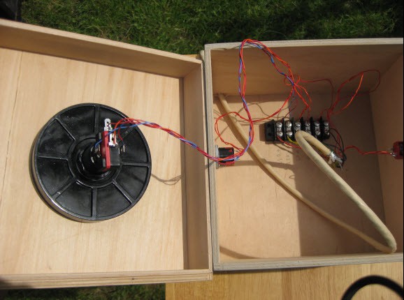
The button box has just the top lighted button, and two key switches on the side, with a simple terminal strip glued to the bottom.
Candle relay box:
This has the previously described relay board for controlling the solenoids and HSIs. When that board was designed, I simply used screw terminals for the inputs. This picture shown prior to connecting the inputs on the left of the circuit board.
Controller breakout:
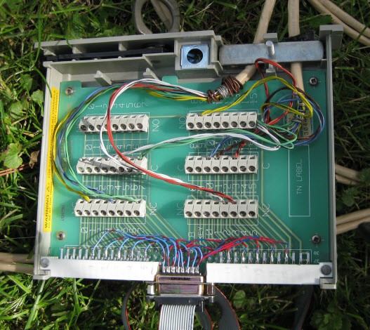
I used a scavenged terminal module for this. The terminal board was originally a module to plug into some old test equipment, and was simply a set of screw terminals wired to a card edge connector. It was a great base because already had the terminals, had a screw clamp for securing the wires coming in, and a plastic case with a quick release cover screw.(cover not shown) To make it work for this application, I simply cut a channel into the [no longer used] card edge connector to mount a DB15, which I wired into the board. A simple ribbon cable connected between this and the controller.
As can be seen in the pictures, I doubled up the wires, stripping and twisting together both wires of a pair to act as one. This was not required, but I had the extra wires, and it reduced the resistance in the long wires. Approximately 200ft of wire was used.
I also wanted to take a moment to talk about connectedness. Being made up of multiple independent units, this project is inherently a connected device, passing communications between these blocks. Further, though not shown here, the controller supports serial communication both through USB as well as through an RS232 level UART.
The USB serial connection is intended to load and save sequences. This allows a more convenient method for visualizing and programming sequences as well as performing backups.
The RS232 level UART is intended to communicate with other smart blocks in the system. For instance, this allows the project to be connected to a stage and lighting controller for firing in sequence with other effects.
Discussions
Become a Hackaday.io Member
Create an account to leave a comment. Already have an account? Log In.