NOTE: No Model M keyboards were harmed in this project. That would be horrible. The modifications detailed herein are completely reversible.
UPGRADING THE MODEL M KEYBOARD CONTROLLER
I decided to put a Zero in my beloved Space Saving Model M keyboard: that's the sort of thing everyone does, right? It shouldn't be too hard - stuff the Zero in there (there's lots of room!), and connect it to the keyboard's controller board using this circuit. Why would I do this, you ask? Because, using the Pi Zero, I could. I'd figure out what I could use it for later!
Then I had an epiphany: the Zero has enough GPIOs to completely REPLACE the keyboard controller. I'd just need to write a kernel module to scan the keyswitch matrix. Since I'd already done about half the necessary work on a previous project, it shouldn't take too long. And as an added bonus, it would consume less than half the current of the original keyboard controller. That would make battery operation possible. And any project that uses 24 GPIOs on a Pi has got to be awesome, right? I could even spin it as "upgrading the Model M keyboard controller" instead of the rather pedestrian "Pi stuffed inside of a keyboard". Bonus!
WRITING A KERNEL MODULE
So I started by writing a kernel module. I decided to write it as a generic switch matrix handling module, in case other people might find it useful. Maybe someone will want to put a Pi inside of a Commodore 64 or something? (Comments are in the source if you want to do this.) Of course I used my favourite switch de-bounce routine. I got basic matrix scanning with n-key rollover working, and started on ghost key lock-out. Then I had a terrible thought: the Linux kernel probably already has a switch matrix module. And sure enough, a quick search turned up the matrix_keypad kernel module.
Oh no, I thought, all that work was for naught!
I went through the matrix_keypad module code to see how it worked. As far as I could tell, it used a simple time delay to de-bounce the switches, not a robust filtering algorithm like mine. And I couldn't find any ghost key lock-out. It gave me the feeling that it was written for small switch matrices, not a full keyboard. It did have the advantage of being interrupt-on-change driven, unlike mine which uses a regular timer tick. So the crisis was averted - my module was definitely better for a full keyboard! I added ghost key lockout to my module, double-checked the translation table, and it was done. I made a device tree overlay for it, and added a reference to it in /boot/config.txt.
IT'S COMPLICATED
Now that the keyboard was working I really needed to figure out what I would use it for. I could use it as a USB keyboard using the USB HID gadget driver. Or a Bluetooth keyboard using a Bluetooth dongle. Or even a WiFi keyboard using a WiFi dongle, so I wouldn't have to add Bluetooth to my Pi 2. (These last two would require batteries of course.) Or even all three, with the mode determined by what was plugged into the USB port! But in the end I decided to concentrate on first making it a simple USB keyboard. Then I wouldn't have to worry about batteries.
That meant I'd need to use the g_hid (HID gadget) kernel module. I thought it'd be simple to get it working, but upon researching it, I found that it needed a data block in HID report format sent to it's device file. And those reports are completely different from how Linux reports keyboard events. The Linux event system sends key-up and key-down events, and the HID report consist of the modifier key states (in a bitmap) followed by the keycodes of up to 6 keys that are currently pressed. These reports are sent only when there is a change in key state. So I wrote a userspace program (called event2hid) to get key events, map which keys are down, and scan this map (when there was a change) to generate and write a properly formatted HID report. Oh, and also translate the key codes since they're completely different!
On top of that, the g_hid kernel module didn't work! It turned out it's incomplete - it needed information that's usually set up in the platform descriptor at kernel compile time. The Pi's descriptor, of course, didn't have this information, and the only way to add it was to recompile the kernel. Which I wasn't going to do, for obvious reasons. (OK, there is also configfs, but I couldn't find clear instructions). It might have been possible to use a device tree overlay to add this information, but I couldn't find any instructions. (If you know how to do it, please leave a comment.) I decided to hack the kernel module per these instructionsinstead. It turned out to be really easy: a quick module compile and I replaced the g_hid.ko file (buried in the modules directory) with the new one. I also needed to add dtoverlay=dwc2 to /boot/config.txt.
SYSTEMD? WE DON'T NEED NO STINKIN' SYSTEMD
And there was another problem: the Zero in the keyboard will be powered off without a proper shutdown sequence. Because of this the SD card should be mounted read-only to limit corruption. That would be a problem: several services need to write to the card. I initially looked at using a union filesystem like the Knoppix live CD uses: it's complicated to set up, but others have (mostly) documented how to do it. Then I realized I didn't need the standard bloated init system at all. A simple shell script would do: then I could control card writes so read-only wouldn't be a problem. And as an added benefit, the Zero would boot up really quickly! I'd used this technique ages ago when I built a Linux system from scratch, where I compiled everything from source. I had to really dig deep to remember what I'd done!
I initially thought I could call a shell script from cmdline.txt, but after several tries (and lots of SD card swapping after crashes!) I wasn't able to figure out how to pass enough parameters to the shell to make it work. I vaguely remembered that in my scratch-build I hacked the kernel to make it work. So I gave up and wrote my own init in C, called mini-init:
int main(void) {

    system("/bin/sh -c /etc/mini-init.sh");
    return 0;

}
That turned out to be easy: it only needed to call sh and instruct it to run a shell script, where all the real work would be done. I compiled it, put the program in /etc, and added init=/etc/mini-init to the end of the /boot/cmdline.txt file. Next I needed to write the /etc/mini-init.sh file. This is what I decided it should do:
- Mount the
procandsysfilesystems since I was starting with nothing but root mounted read-only. - Load all of the modules in correct order since
modprobedidn't seem to work correctly. Even the modules called out in the device tree overlays needed to be loaded. - Disable handling of Linux's magic SysRq key so that all key events would be sent out.
- Disable video output to save power.
- Lastly, run the
event2hidprogram.
How did I figure all this out? Lots of crashes, dead keyboards, and SD card swapping. Here's what I ended up with:
#!/bin/sh
echo Processing mini-init.sh...
version=`uname -r`
echo Kernel version is $version
/bin/mount -t proc /proc /proc
/bin/mount -t sysfs /sys /sys
/sbin/insmod /lib/modules/$version/matrix2pi.ko
/sbin/insmod /lib/modules/$version/kernel/drivers/usb/gadget/udc/udc-core.ko
/sbin/insmod /lib/modules/$version/kernel/drivers/usb/dwc2/dwc2.ko
/sbin/insmod /lib/modules/$version/kernel/drivers/usb/gadget/libcomposite.ko
/sbin/insmod /lib/modules/$version/kernel/drivers/usb/gadget/function/usb_f_hid.ko
/sbin/insmod /lib/modules/$version/kernel/drivers/usb/gadget/legacy/g_hid.ko
echo 0 > /proc/sys/kernel/sysrq
/opt/vc/bin/tvservice -o
/sbin/lsmod
/etc/event2hid
echo Done with mini-init.sh, dropping to shell...
/bin/bash
HOW I BUILT IT
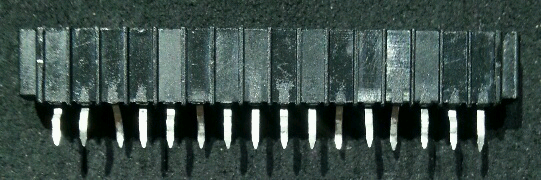
I flattened the 16 pin connector leads. Then, from the left in the picture, leads 3, 6, 11, and 13 were bent down a little bit, and the remaining leads were bent up a little bit. The bends were to force some pins into the odd GPIO holes, and the others into the even holes:
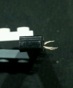
This end view shows how the leads were bent:
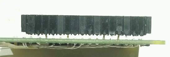
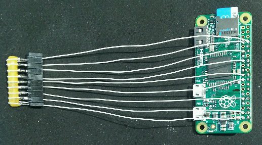
I soldered the connector to the BACK of the Zero. The connector was positioned with ridges away from the Zero, all the way to the end: pin 16 went into hole 40 on the Zero. It sat above the Zero a little bit, so after this photo was taken I filled the gap with hot glue to make it more durable:

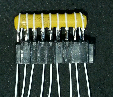
I flattened the 8 pin connector leads. I soldered the 22K 8-resistor bussed array to them, and finally soldered on 5 inch long wire wrap wires. It's kind of hard to see in the photo but the pin on the array that has a dot by it (at the left) doesn't line up with a connector pin: it's only connected to a wire. This is the array common pin. I put epoxy where the wires wrap around the array to act as a strain relief:
I soldered the other end of the wires to the Zero. I found it easiest to solder the wires in from the component side: I tinned the wire, filled the hole with solder, then inserted the wire while keeping the solder liquid. After this photo was taken I put hot glue around the resistor array/socket pins for insulation. This picture was also the closest I got to making a proper schematic - not very close:
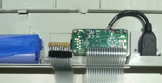
I made a little mounting plate with two holes in it, to which the USB socket was glued with Epoxy. The assembly fitted over the locating pins on the keyboard base, and was held down with double sided foam tape. After the glue was cured, I cut, stripped and soldered the wires from the socket to the Zero. After this photo was taken I reinforced the connections with hot glue and connected the shield wire to the metal plate under the keyswitches:
I used a mounting plate for the Zero. I was worried that the whole thing would look kludgey, but as you can see, everything mounted beautifully. The batteries will be used in the future:
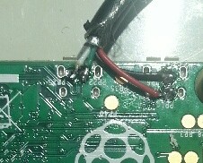
I made a USB A-A cable by taking apart a USB connector from an old keyboard and soldering it to the cut-off end of another keyboard cable. I wired it straight through, not crossover. In other words, pin 1 on one connector was connected to pin 1 on the other connector, etc. Since I was extra paranoid about letting the "magic smoke" escape, I left the red wire un-soldered at the Zero and measured the voltage between it and the black wire when the A-A cable was connected to a computer. It read +5 volts, so I soldered the red wire to the Zero.
AFTER ALL THAT, DID IT REALLY WORK?
Most assuredly! I used it to type this write-up, connected to a Model 2B. The only problem I've found is occasionally the keyboard doesn't power up properly. Re-plugging it solves the problem. I think it's probably the 5V power ramping up too slowly on my Pi 2. I'll investigate using it's USB port power control feature to cycle power on the keyboard USB port.
WOULD YOU, A MERE MORTAL, BE ABLE TO BUILD THIS PROJECT?
Certainly. See the build instructions.