 Lemniscate snickets
Interfacing with Myo
Myo provides a C++ SDK for MS Windows and MAC OS X, sadly no linux ;(
The Myo SDK allows access to thalamic gestures:
- Fist
- Fingers Spread
- WaveIn
- Wave Out
- Double finger tap
Additionally we have access to the IMU data from the band, such as yaw, pitch and roll.
These inputs were mapped to the following outputs:
- Fist
- Stop the robot
- Fingers Spread
- Go forward or backwards
- WaveIn
- Go right forward or backwards
- Wave Out
- Go left forward or backwards
- Double finger tap
- Changes mode from forward to backwards & vice versa
- Pitch value given by Myo from 0 to 18.
- 0 to 9 (arm down to arm parallel to ground)
- Robot is stopped
- 10 to 18 (arm parallel to ground to arm up)
- Pitch was mapped to the PWM value (0 to 255)
- Four speeds implemented, depending on the pitch
- 20% PWM
- 46.67% PWM
- 73.33% PWM
- 100% PWM
- 0 to 9 (arm down to arm parallel to ground)
- Modifications were made to myo listener for faster refresh rate.
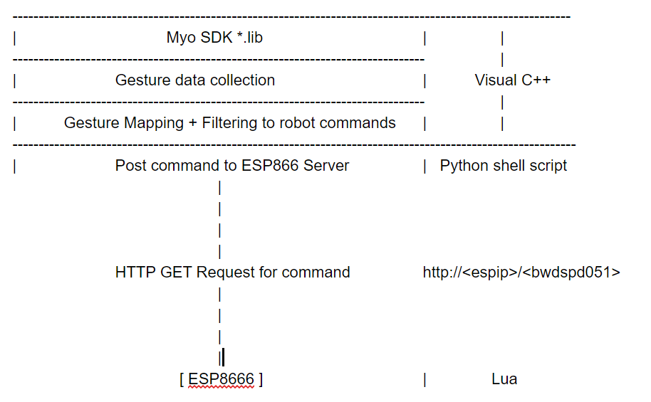
- The C++ program calls a python script that is launched as a child process and takes input the command to post to the ESP
- The python is a simple urllib2 script that does a HTTP GET request to the server for that command.
- The ESP (lua script) receives the request which it parses to get the command and outputs it on it serial port.
Base Side Implementation Stack :
Lua script running on the ESP that parses the GET request and outputs the command on its serial.
Since the spark core was not working, we ending up deploying a web server on a ESP8626
The python script is launched as a child process by the C++ Program whenever it needs to post a command ( Yes we know it’s very hacky!) with the command as an argument to the script that it needs to do a post of.
The ESP receives the GET command and parses the url to get the command which it writes to its serial port.
Challenges and Operation Details :
- Piping myo data to the robot:
- To pipe data to the robot we initially selected the spark core, that would allows us to pull data from spark cloud. Where the sensor data would be pushed from the laptop on which the SDK APP is running.
- Quite some time was spent on making the spark core work:
- Spark Cores were already owned so we couldn’t register them to the spark cloud.
- Solution: Flash the cores locally over usb.
- Spark Core would not connect to wifi due to non-support for WPA2-Enterprise by the TI Wifi chip.
- Solutions tried:
- Windows wifi hotspot -- Spark Core did not detect.
- Additional Wifi dongle hotspot -- Spark Core did not detect.
- Wifi hotspot in linux on vm with the wifi dongle -- Spark Core did not detect.
- iPhone hotspot -- Spark Core did not detect.
- Interfacing the ESP to the C++ myo app
- HTTP libraries for C++ and overtly complicated, especially those provided by Microsoft since we are tied to the windows by myo.
- But python has very robust standard networking library.
- The python script takes the command to send as an argument.
- Python lib urllib2 that opens the url at the
- Whenever the myo app needs to send a command it launches the script as a child process with the command as the input argument
void sendCommandtoEsp(std::string command_input) { std::string arg = command_input; std::string command = "python send2esp.py "; std::string systemcommnad = command + arg; system(systemcommnad.c_str()); // launch python script } |
- Autonomous path
Autonomous path was left unimplimented, due to integration issues with esp and the raspi, line feeds are being appended propoerly
CAD & 3D Printing
In order to support the hardware of our robot and give it a nice visual aspect, we created a CAD model for a base to place on top of the robot.
A first iteration was sent for 3D printing, unfortunately it failed as the printing head was hitting on the sides of the machine because our piece was too close to the allowed limits for the printer.
Therefore, it was split up in two parts which we would glue together. The first half worked, the second did not. The 3D printer could not properly print it.
We tried that last piece another time, still didn’t work. We tried a third time with more support, still did not work.
Thus we ran out of time, so another more viable solution was chosen:
We created a base out of wood and styrofoam, which we screwed to the platform, plus a support tower for the blinky matrix made out of popsicle sticks.
Each piece of hardware is enclosed is a “fence” of styrofoam to hold it into place and organize.


CAD Model top
Blinky Matrix
The blinky matrix is meant to be an indicator of the state of the robot, whether it’s going forward, right, left, stopped, etc.
The blinky matrix pre included an arduino, which had to be desoldered to connect the blinky to the arduino we are using on the robot, in order to synchronize the states.
Programming the arduino to run patterns on the blinky natrix was more challenging than expected, because each animation, according to tutorials and examples, was initialized as an object from class Animation, which took around 40% of the space allocated to global variables. Having around 10 different animations, that seriously impaired our original idea.
We ended up using a pointer dynamically reallocating the Animation with a new set of data, using only the space of one object.