 [skaarj]
I had to modify the final stage. It takes too long to build the audio output transformers - since the first round reward took some time to arrive - so while surfing on the HackChat, one post of @Benchoff sparked me an idea...
- Input stage and equalizer stays the same;
- my vacuum-tube-modified sound card stays away for now;
- final stage rebuilt with some usual and some not-so-usual components.
Ingredients:
- 2 x Nokia classic chargers, transformer-based, 5Volts output;
- 4 x RV12P2000 (or RV12P4000?) Wehrmacht-issued medium power pentode vacuum tubes, made in 1940s. Only 3 pieces RV12P4000 shown in the picture. On top of the middle tube it is written "18/44" - manufactured during week 18th of the year 1944. On bottom it says "Wehrmacht's property";
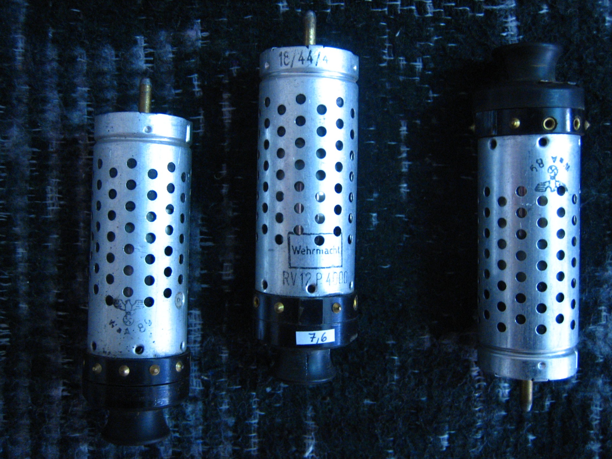
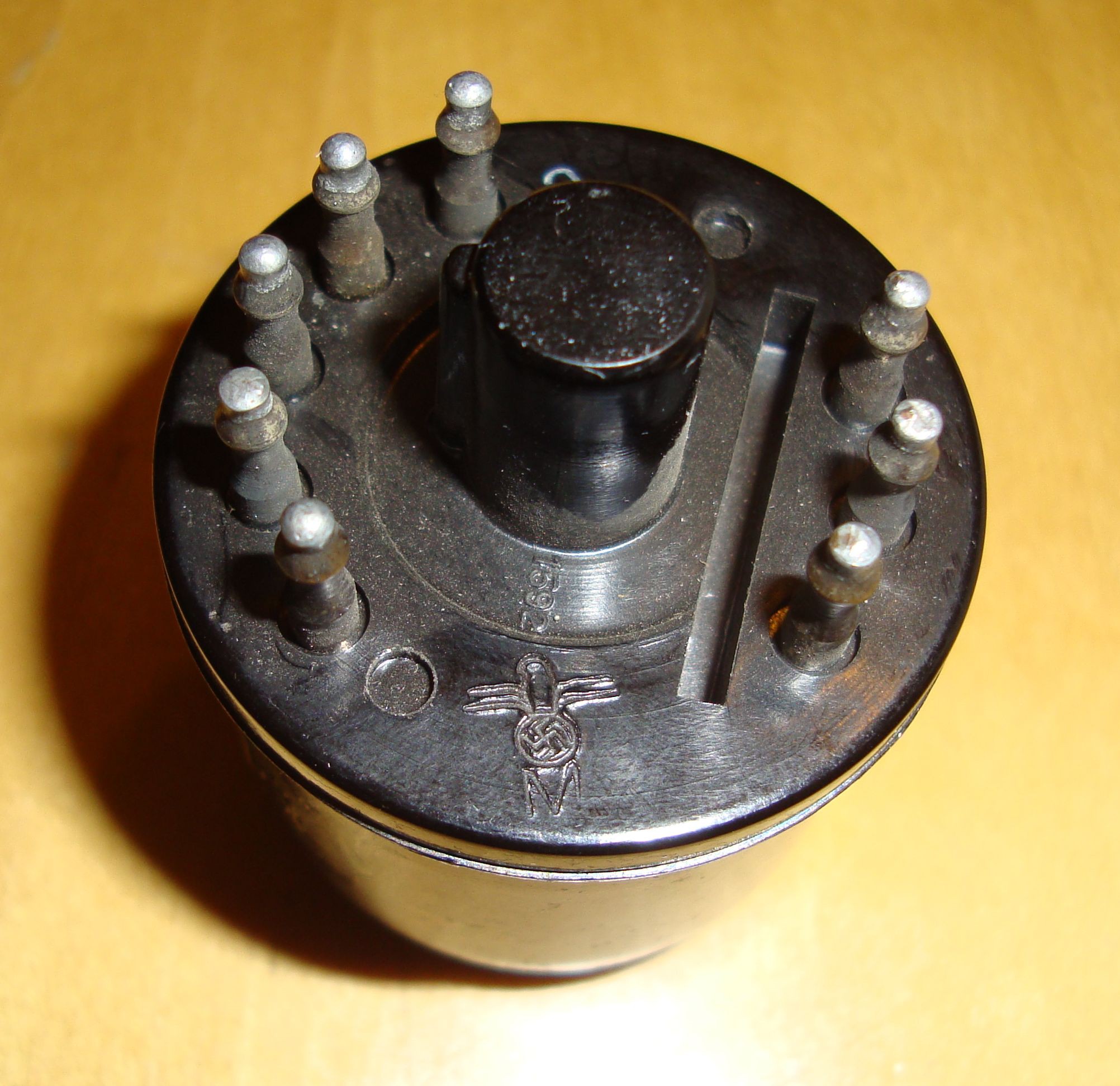
- 2x EZ11 Wehrmacht-issued rectifying double-diode, metallic enclosure, made also in the 40s;
- 2 x volume control multi-turn resistors;
- 2 x high voltage transformers;
- a bunch of resistors and capacitors;
- 2 x enclosures beautifully painted - recycled from trash dumpsters;
- 2 x enclosures from switching vibrators;
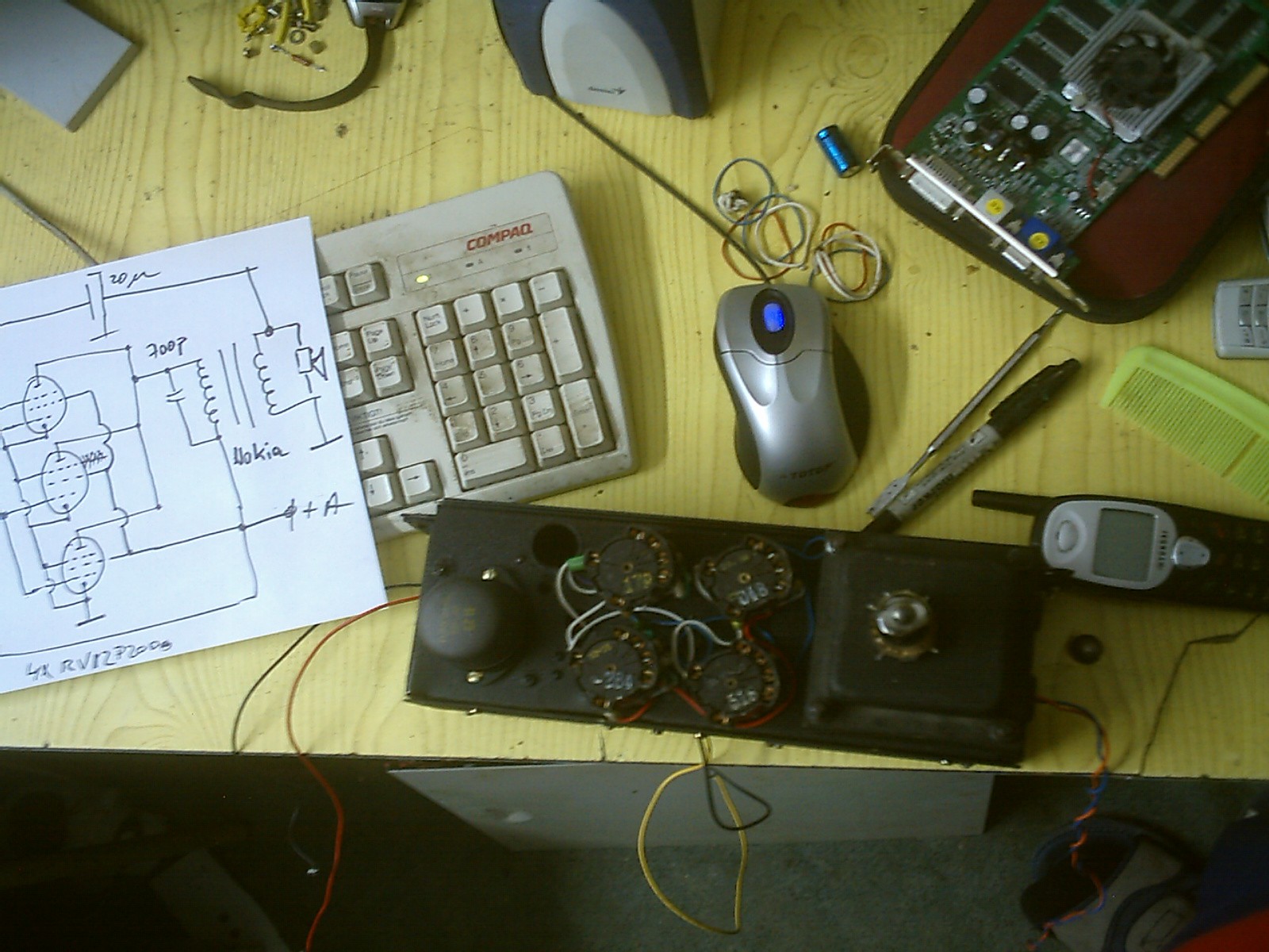
- my schematic.
First we prepare the audio output transformers. Those Nokia transformers will get their cores dismantled into the basic components: the "E" sheets and "I" sheets. These will be reinstalled separated, like this: first the "E"s, then a piece of paper 2mm thick and boiled in automobile engine lubricating oil, then the "I"s. We need to do that to keep the magnetic field opened in the core, or else we will lose power from the pentode stages and also wear the vacuum tubes in time.
Schematic, hand-drawn as usual:
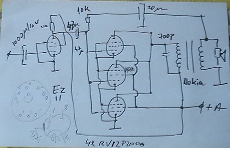
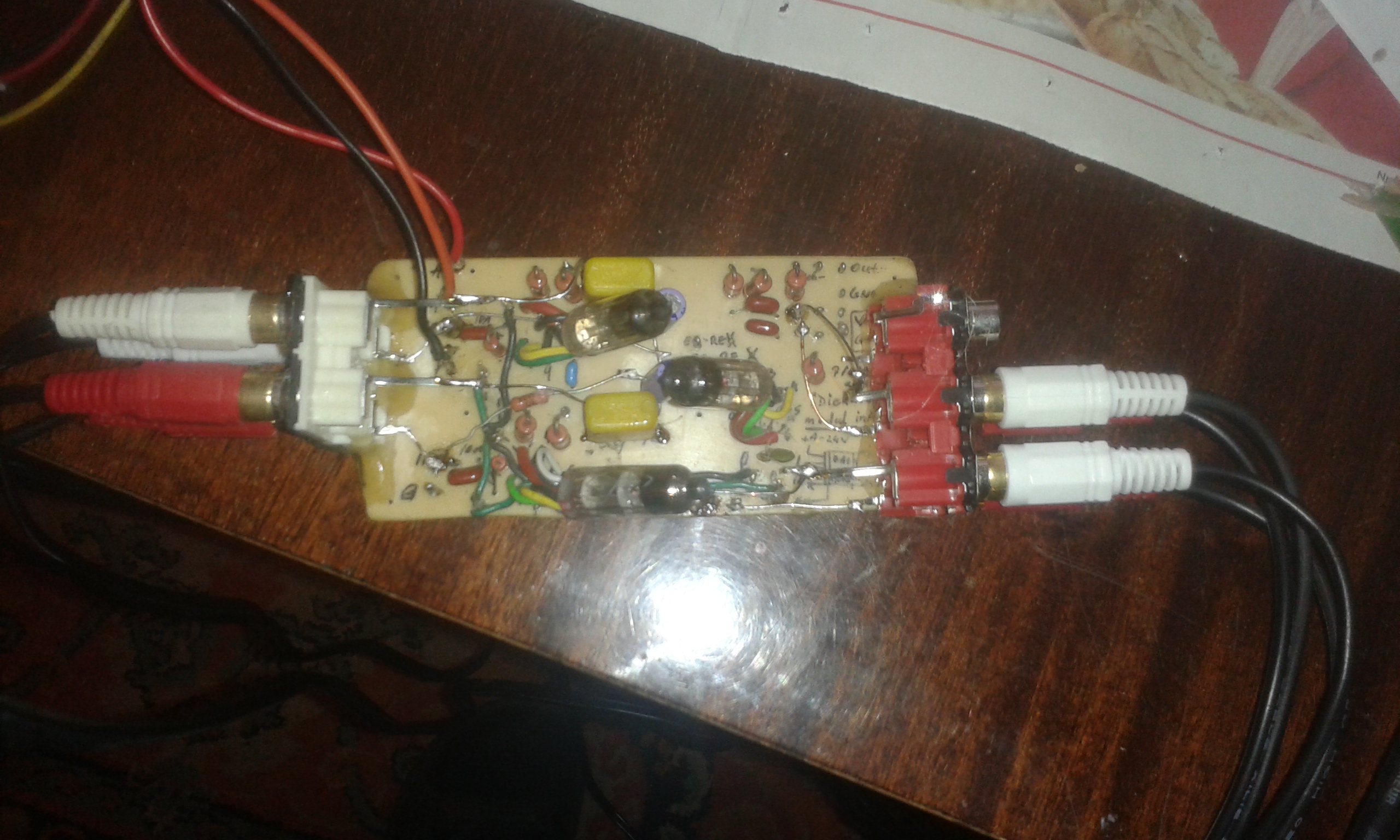
The audio signals input goes through a 1000uF/16V capacitors, then in the first grid of the first RV12P* tube - which in this case is configured as a triode (G2 connected to cathode). Signal separation from anode is made with a 47uF capacitor, and the feedback loop is done through 10k-20uF group. The other 3 tubes are connected in pentode configuration in parallel. 700pF capacitor needed to cut down in-tube electric discharges in case of high input level. Also smooths the sound. Nokia transformer is connected with 220V primary stage between anodes and +A (around +196V). Secondary wiring (5V) goes to speaker. Rectifier stage is the simplest half-wave rectifier- classic schematics are on the internet.
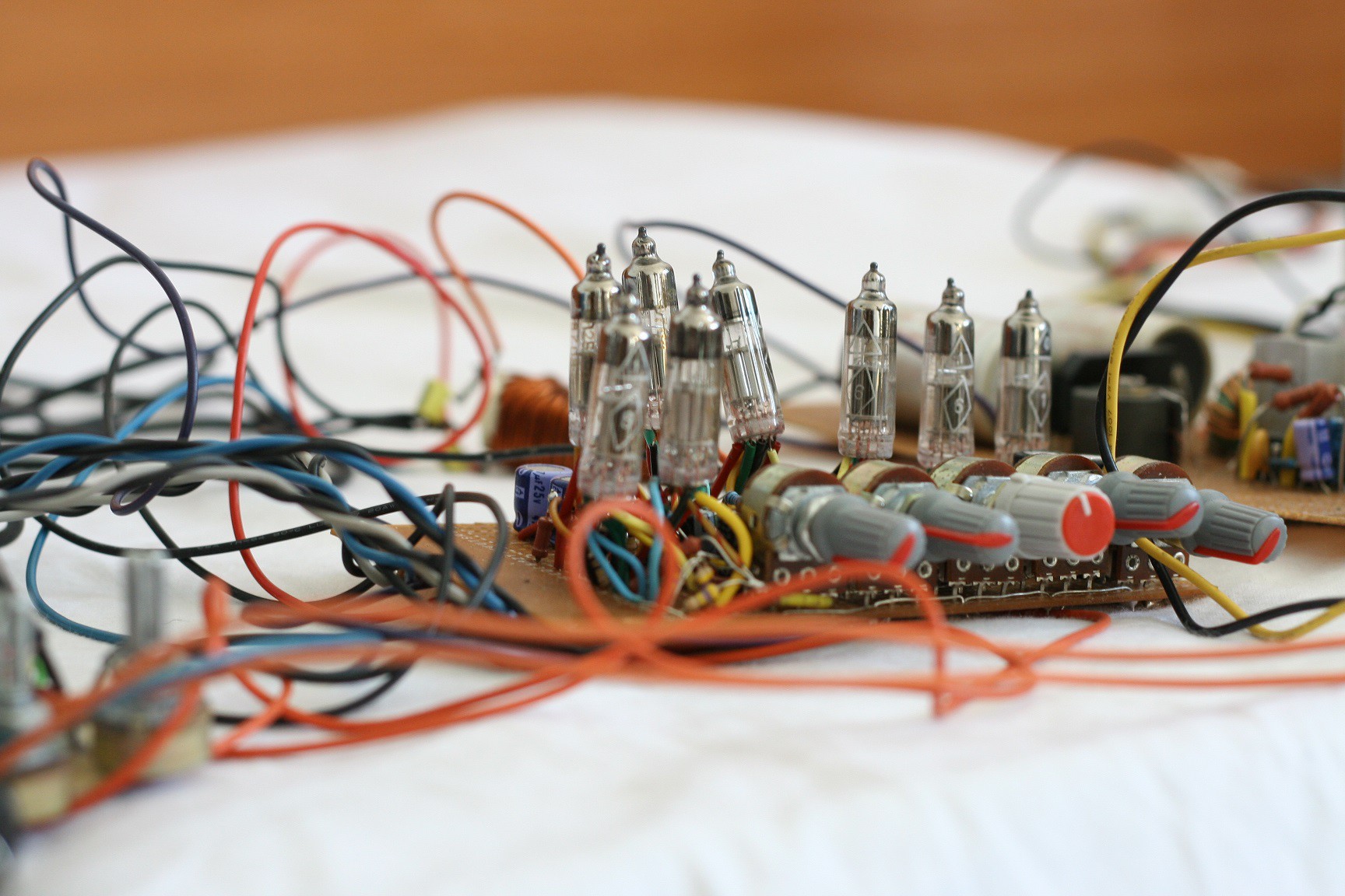
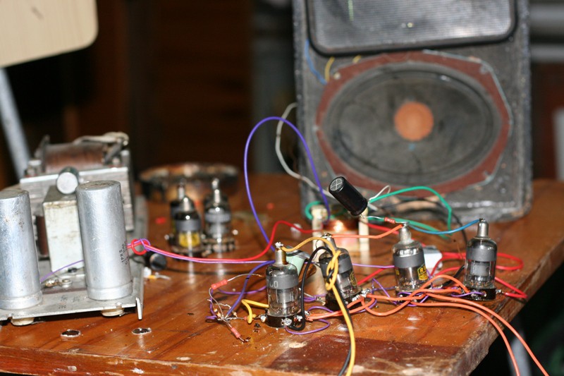
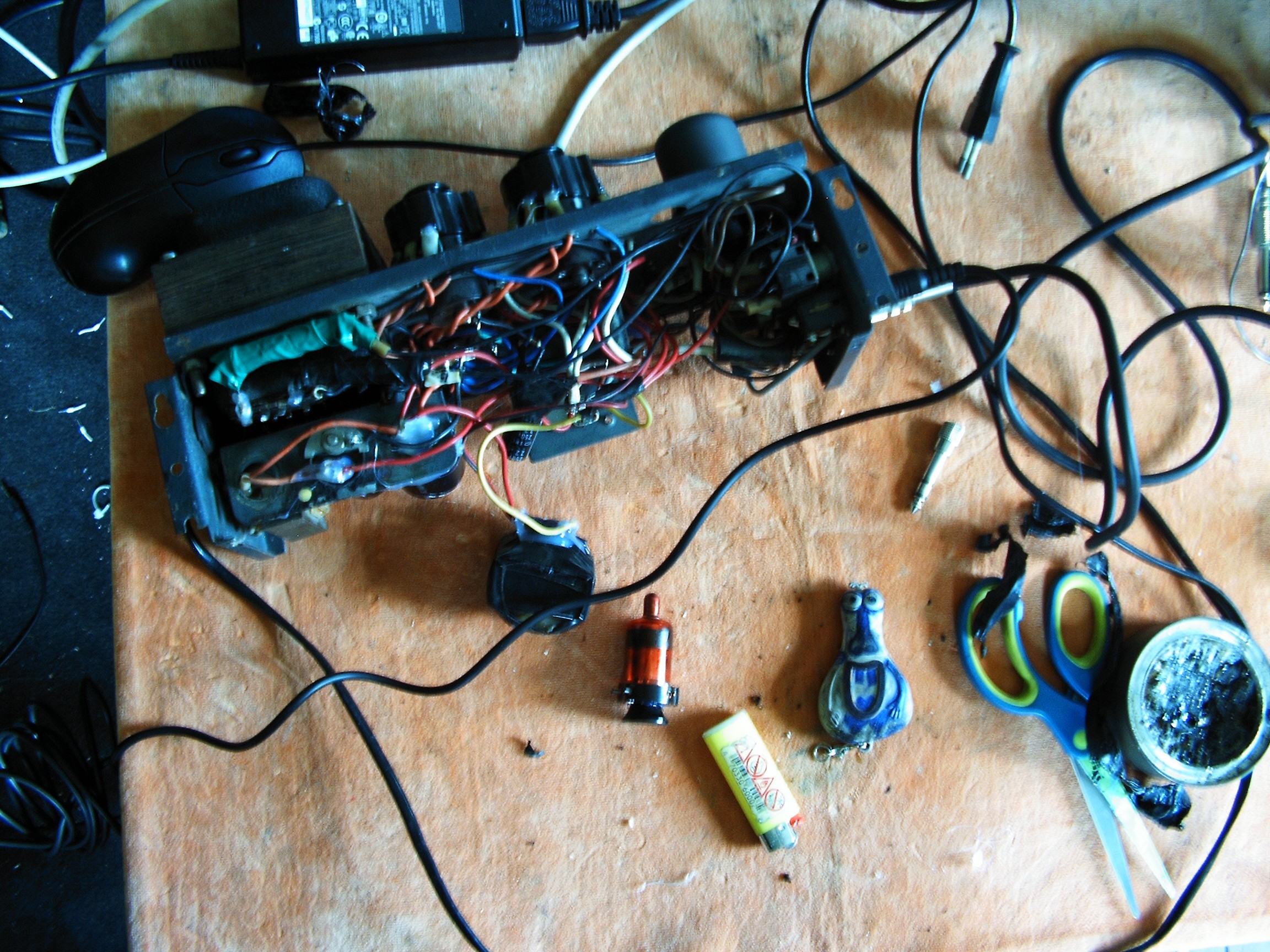
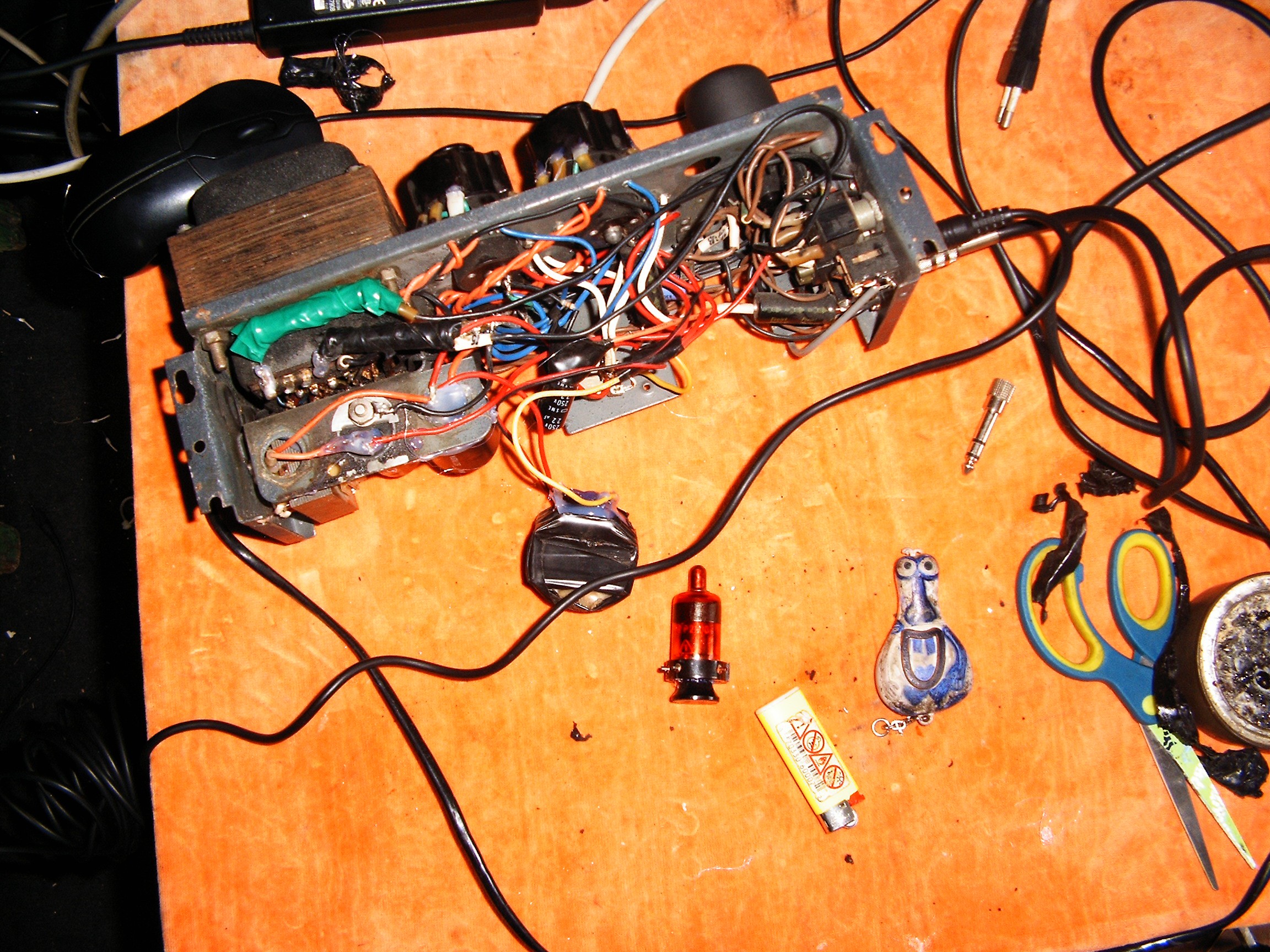
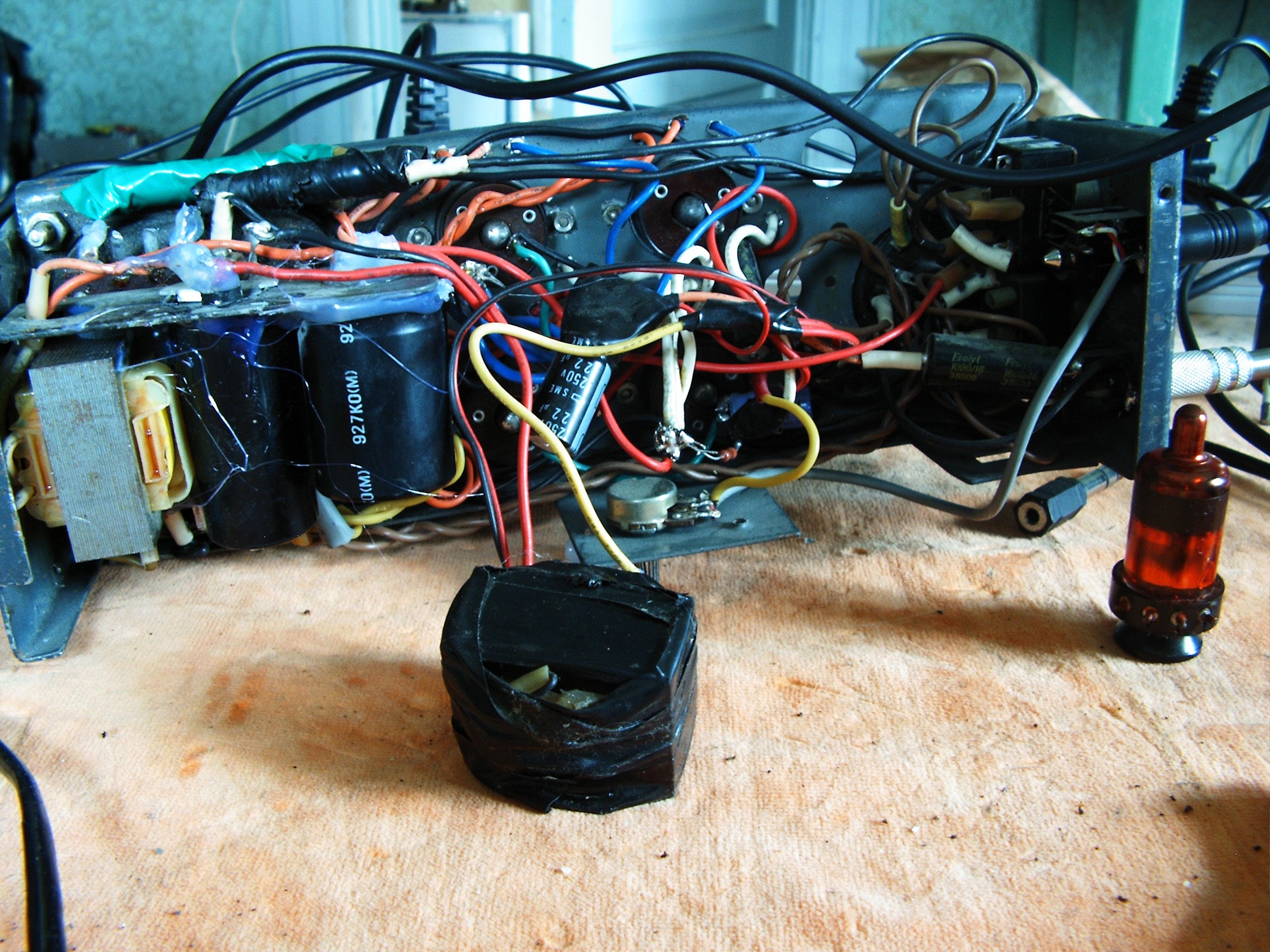
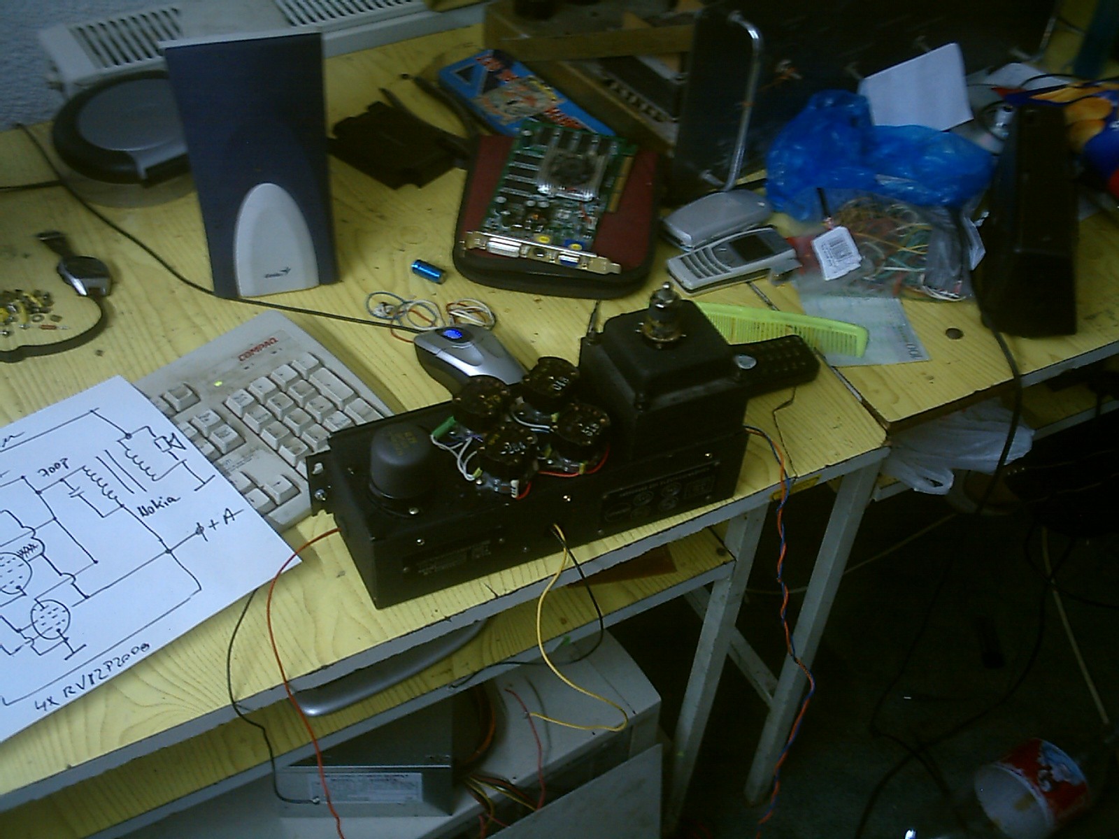
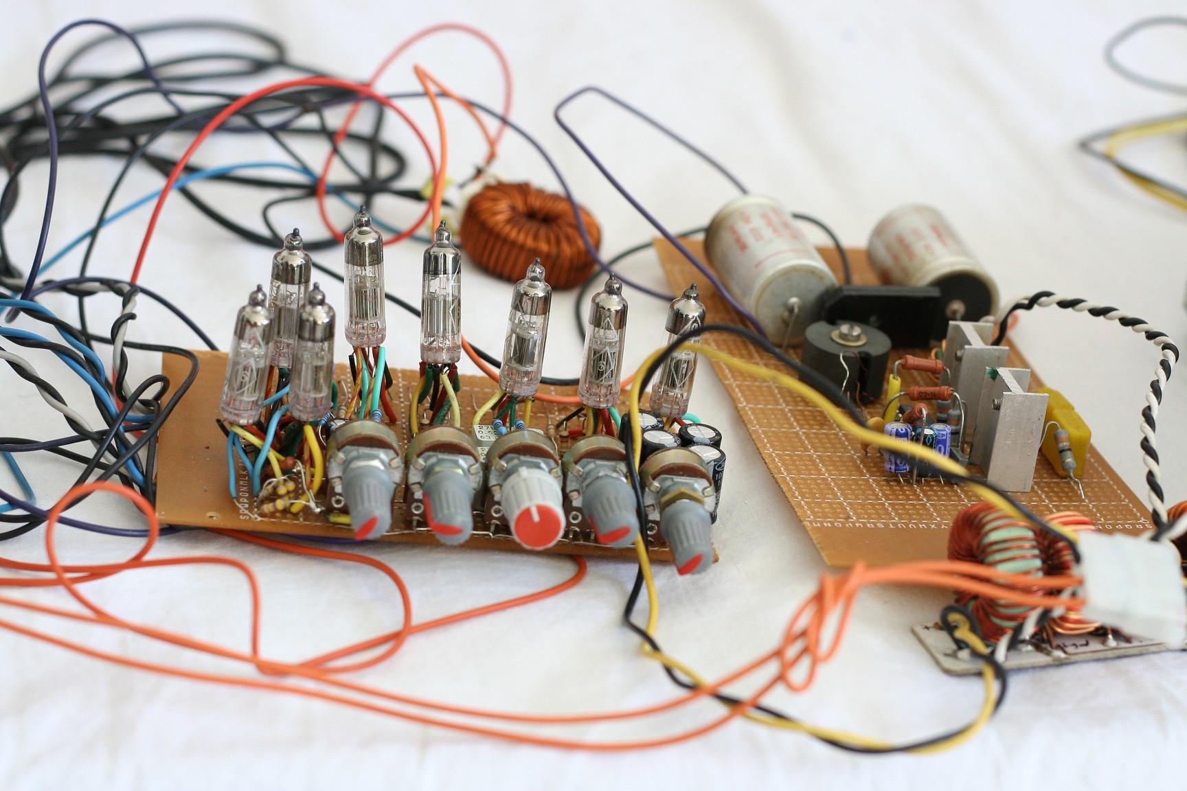
The built final stages look like this:
"Naked" vacuum tubes. Not connected inside sockets.
This, my dear friends, is Romanian Wooden Breadboard on Steroids, powered by +200 volts. This is serious stuff, if you start working at this level you will understand that five volts is for pussies. This is not a game, it is dangerous and requires a lot of attention. Not for people with heart problems. Five volts only - that's simple child play.
Nokia transformer in the background. The sound is GREAT, even if it comes from that trashed speaker. The sound coming from an old reel to reel tape player is like an erotic wet dream for the ears.
Unfortunately I could not find any RV12P4000 sockets, so I'm stuck with the smaller tubes.
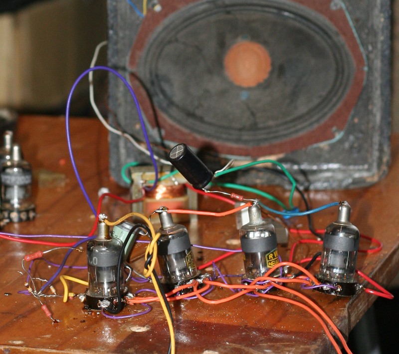
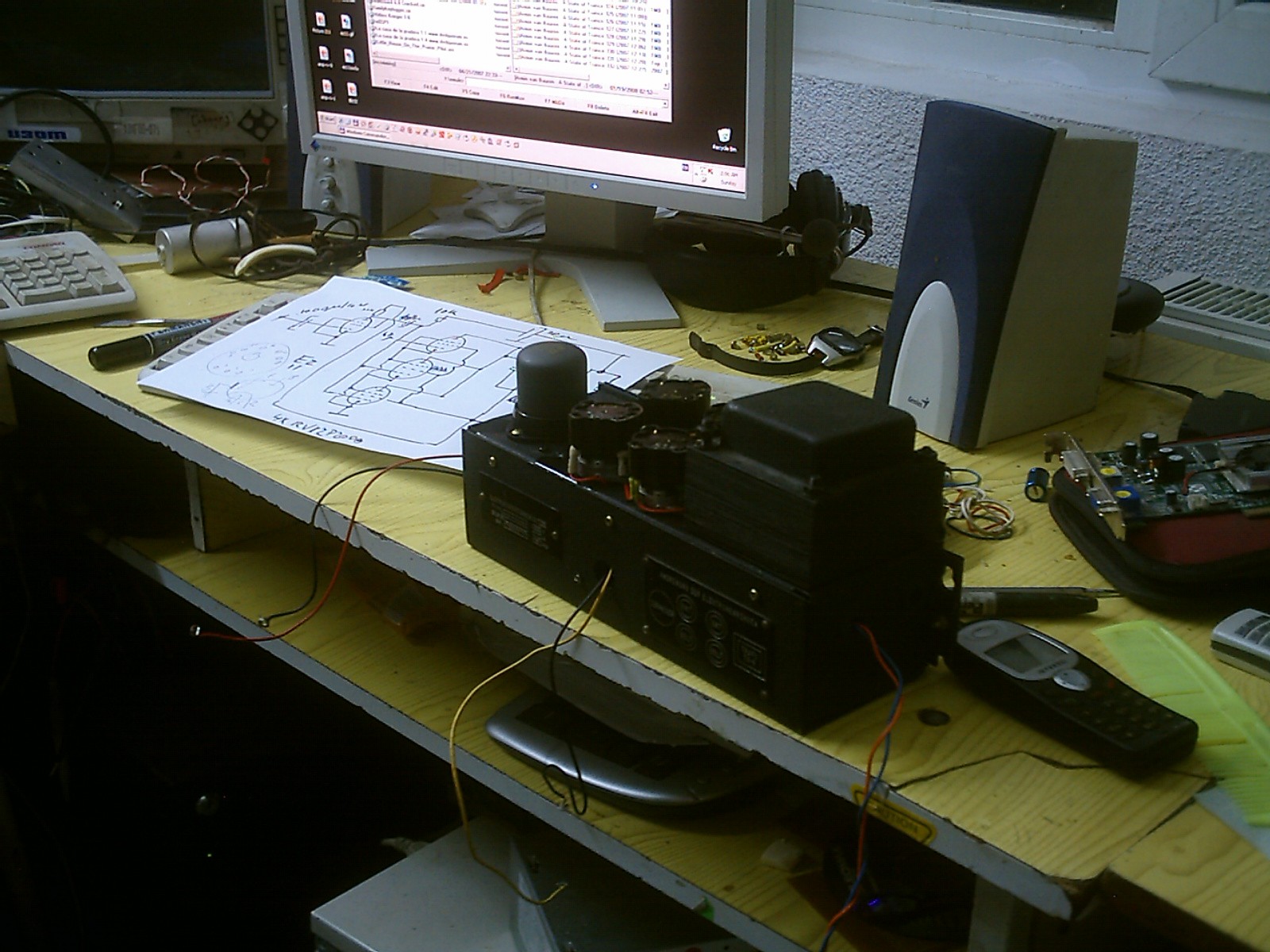
Amplifier rebuilt in some random case I found in the trash dump...
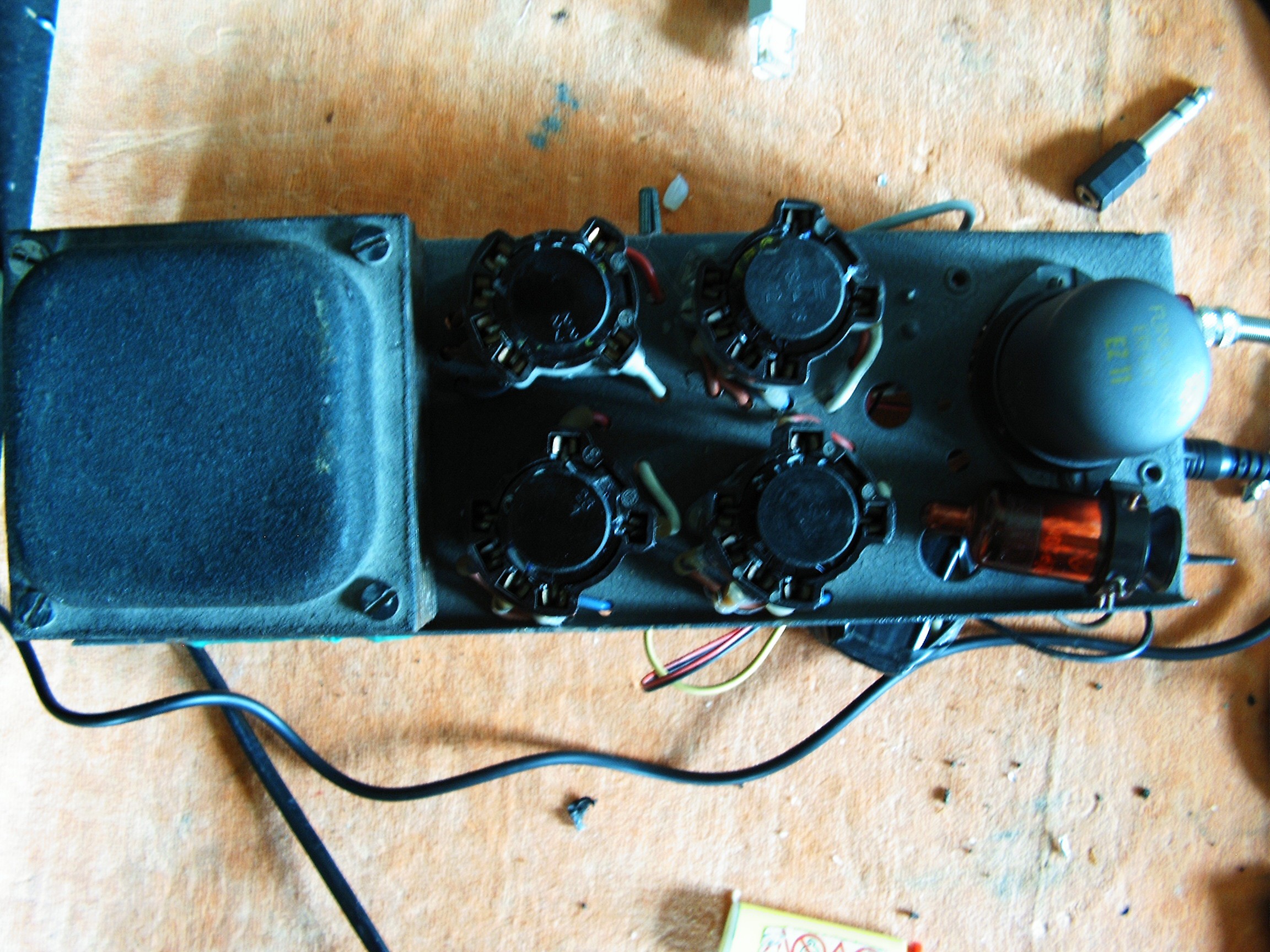
Inside sockets those tubes are connected upside down. There's a tube placed on the transformer as a reference.
This is the left channel.
Now the right channel:
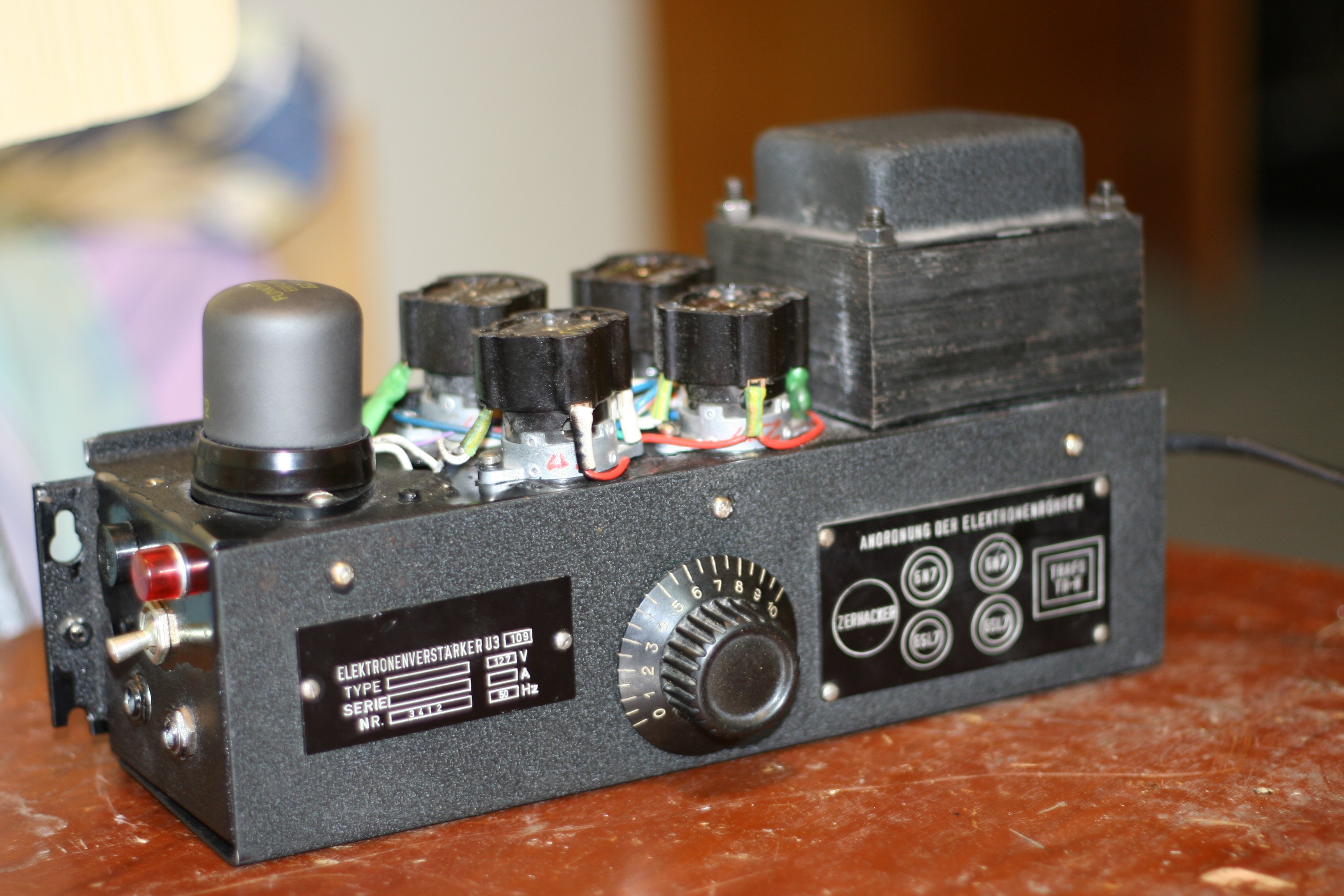
Yes, the enclosures look the same. They are from some old automatic graphing devices which painted some lines using a pen and a mobile arm.
RV12P2000 was very very popular from the 30s until the 60th. Russians took it, changed the socket and glass enclosure and re-named it 12J1L. 12 means 12V filament, J means pentode, series 1, L means glass-aluminium enclosure. Then more variations were made: 2J27L, 6J6 (glass-steel enclosure), 6J1P (EL95), 6J1B (subminiature). And many many other "J" variations.
Instead they were unable to copy RV12P4000, which has a huge amplifying factor.
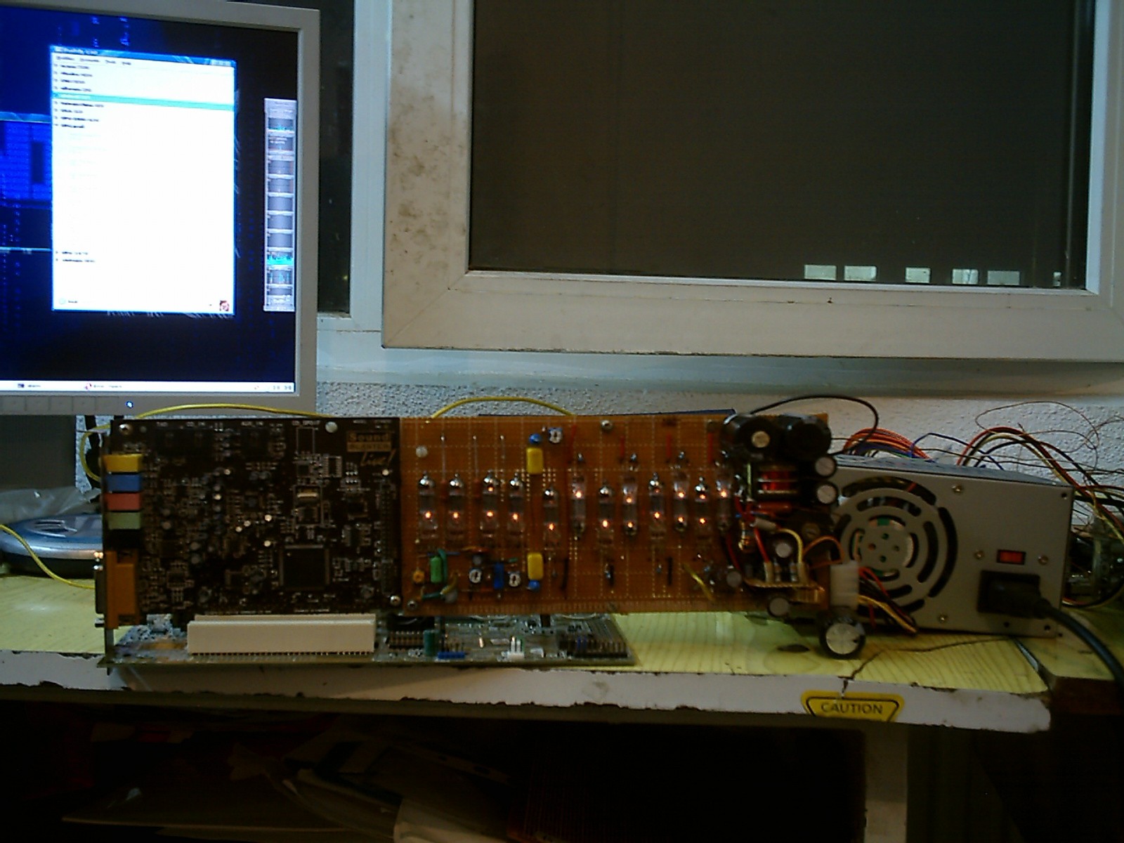
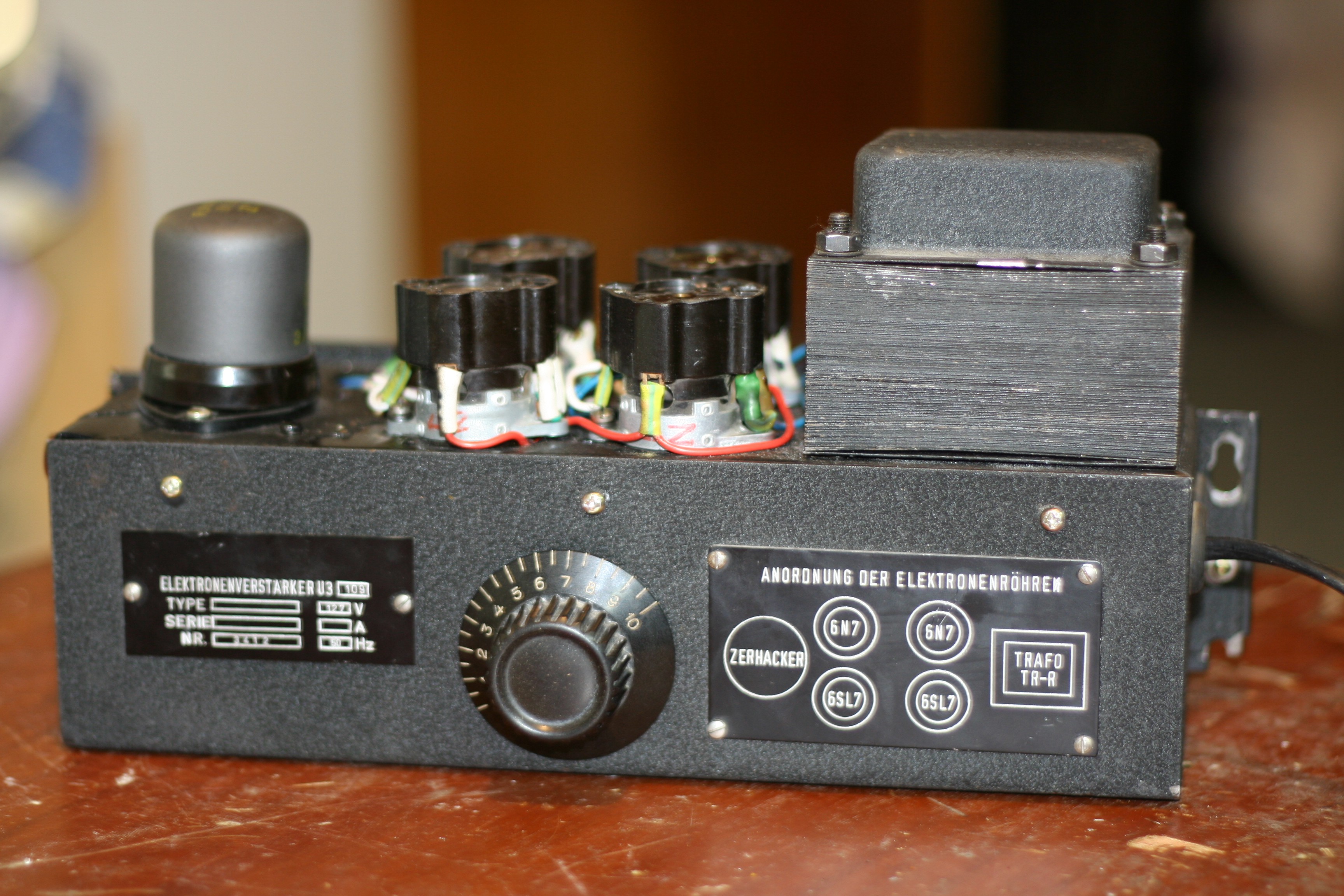
Now, the final stage re-built using Soviet Union tubes: 6H6P triodes (first valve in schematic) and 6F3P (ECL84) instead of the other three pentodes in parallel. This is a double-amp, meaning it is already stereo. Unfortunately the transformer is unable to handle it, it is too small. The enclosure is from the same type of graphing device - but Russian made. Also recovered from trash.
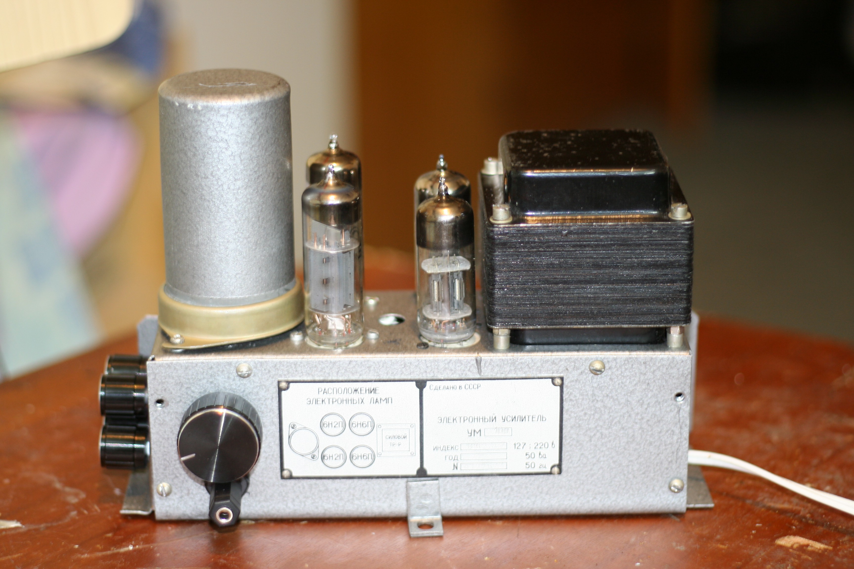
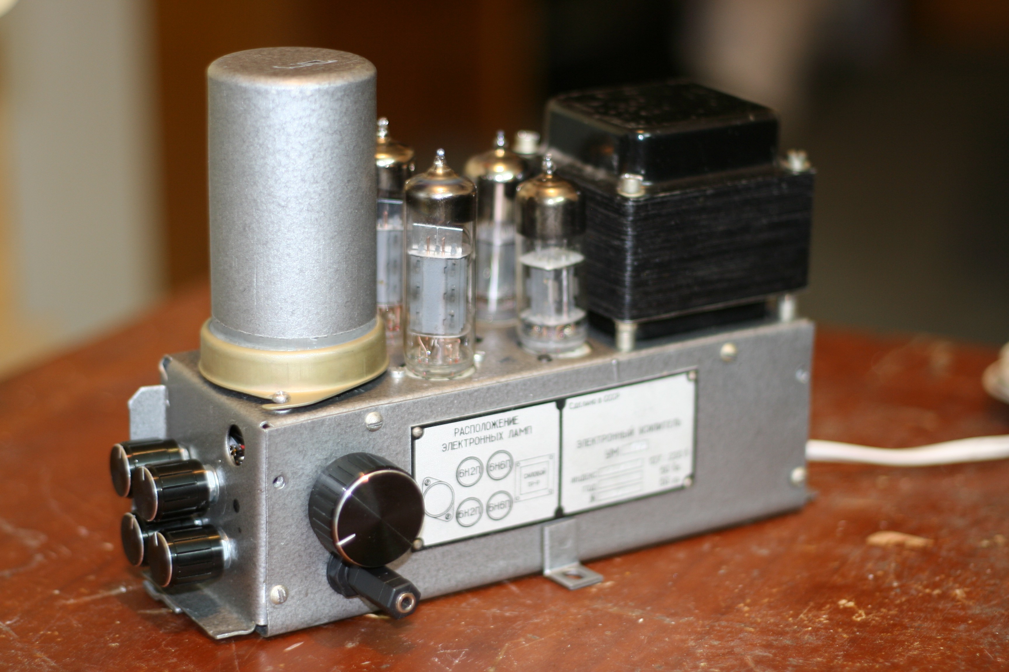
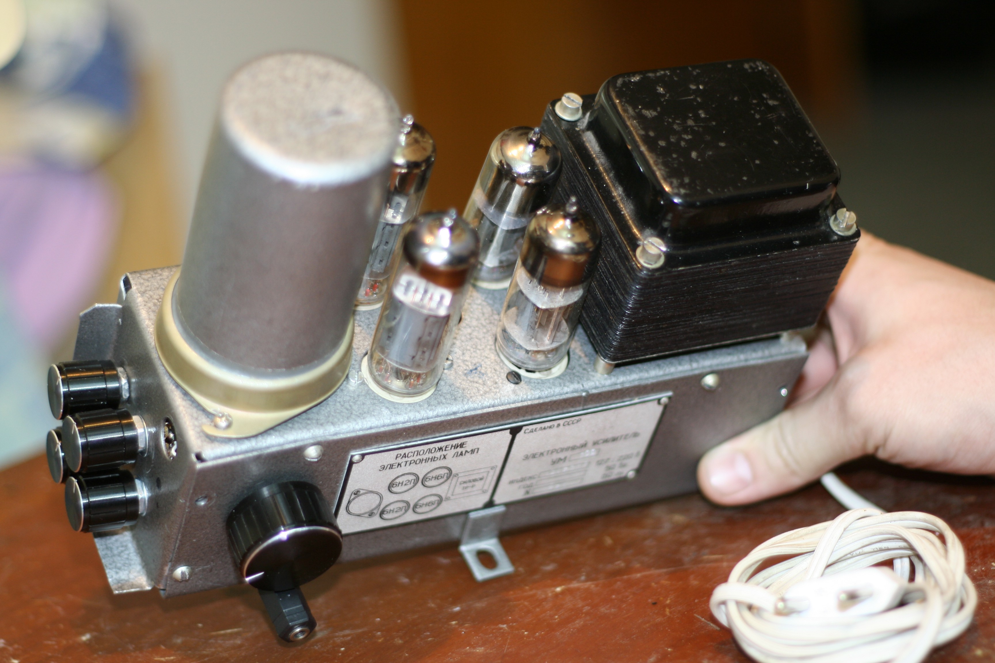
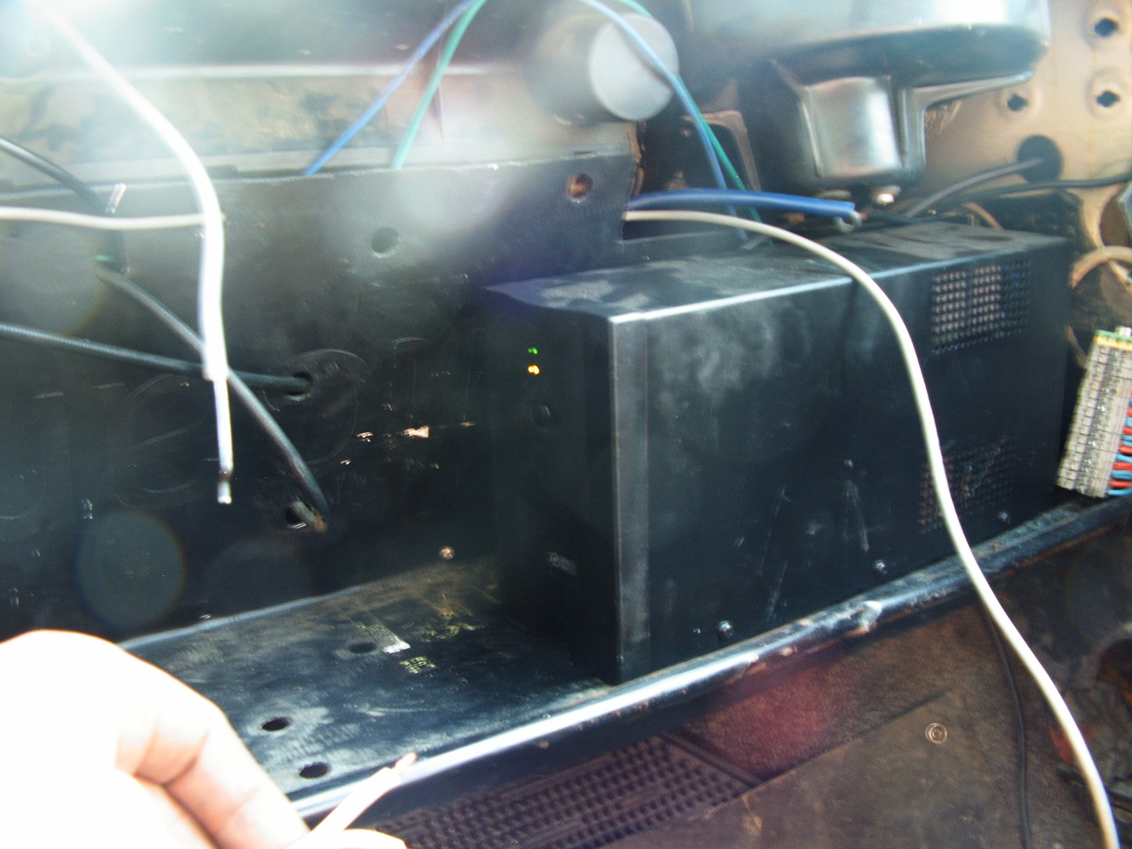
The gray big cylinder metallic enclosure (left side) covers the Nokia transformers.
Again - Soviet Russia vs. Germany but fighting in Audio War. Tests will determine which one is suitable: two German mono amps or one Russian stereo amp.
The winner should fit in the audio system enclosure and will be powered up by the UPS mentioned two logs before:
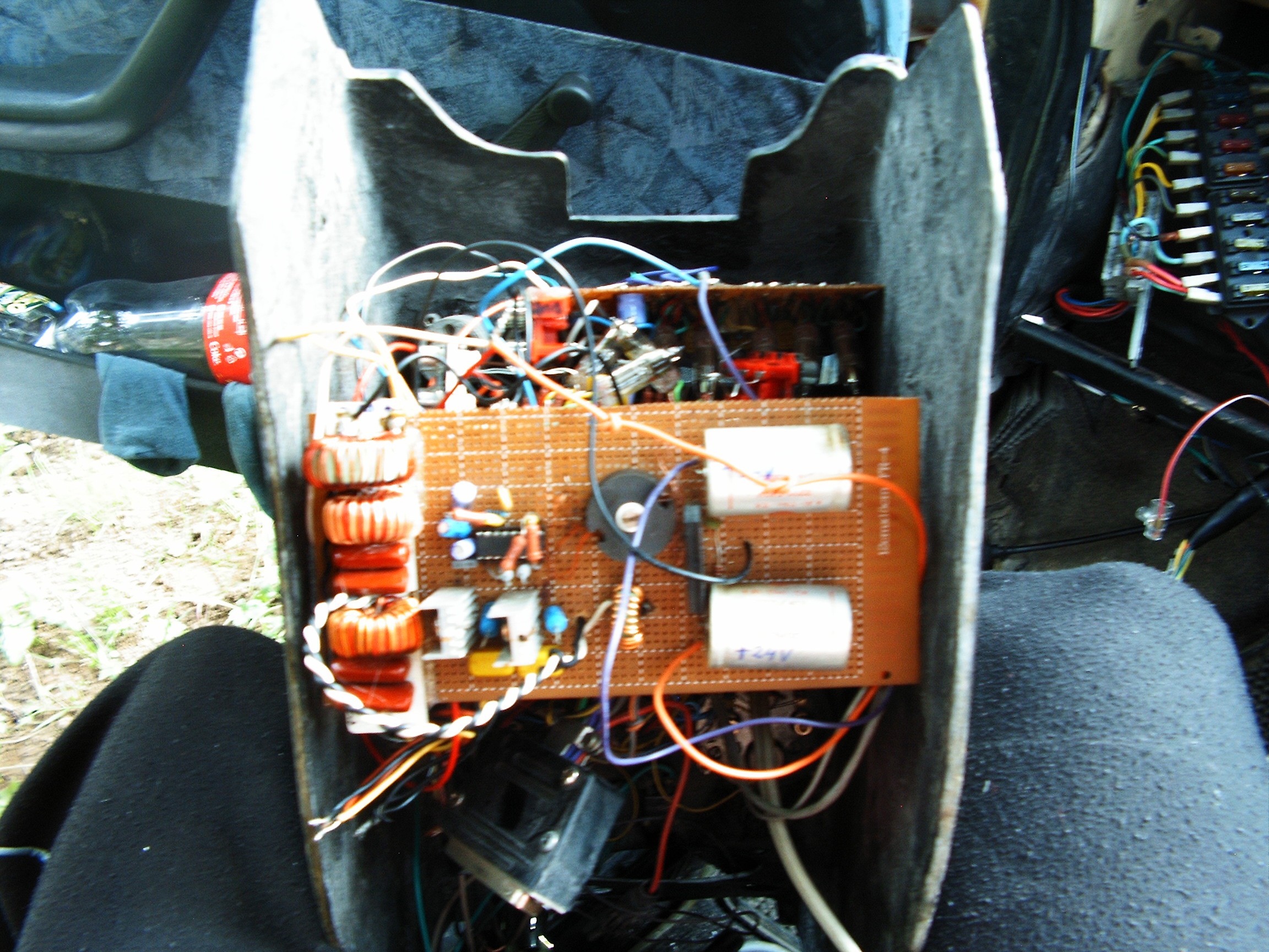
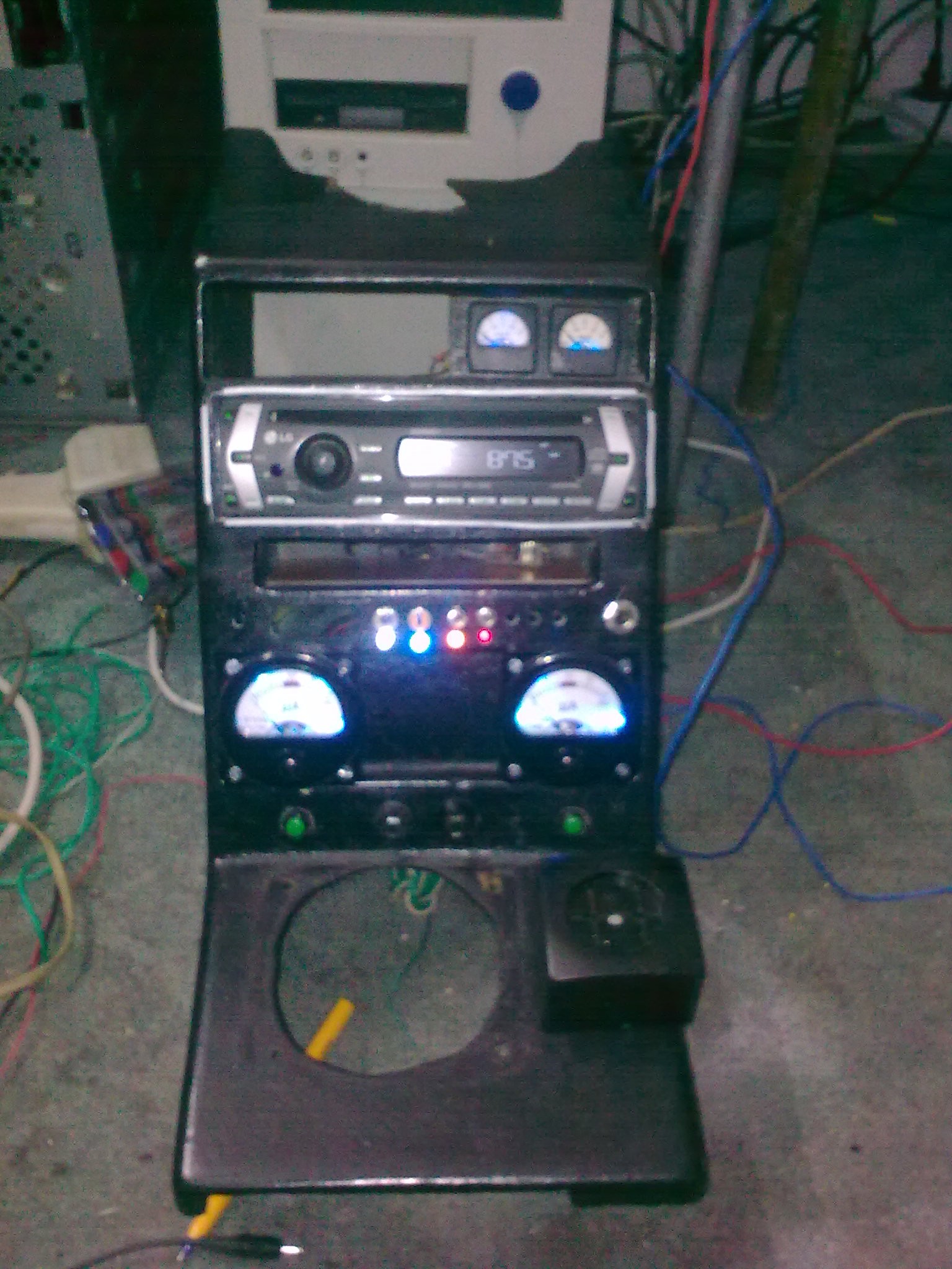
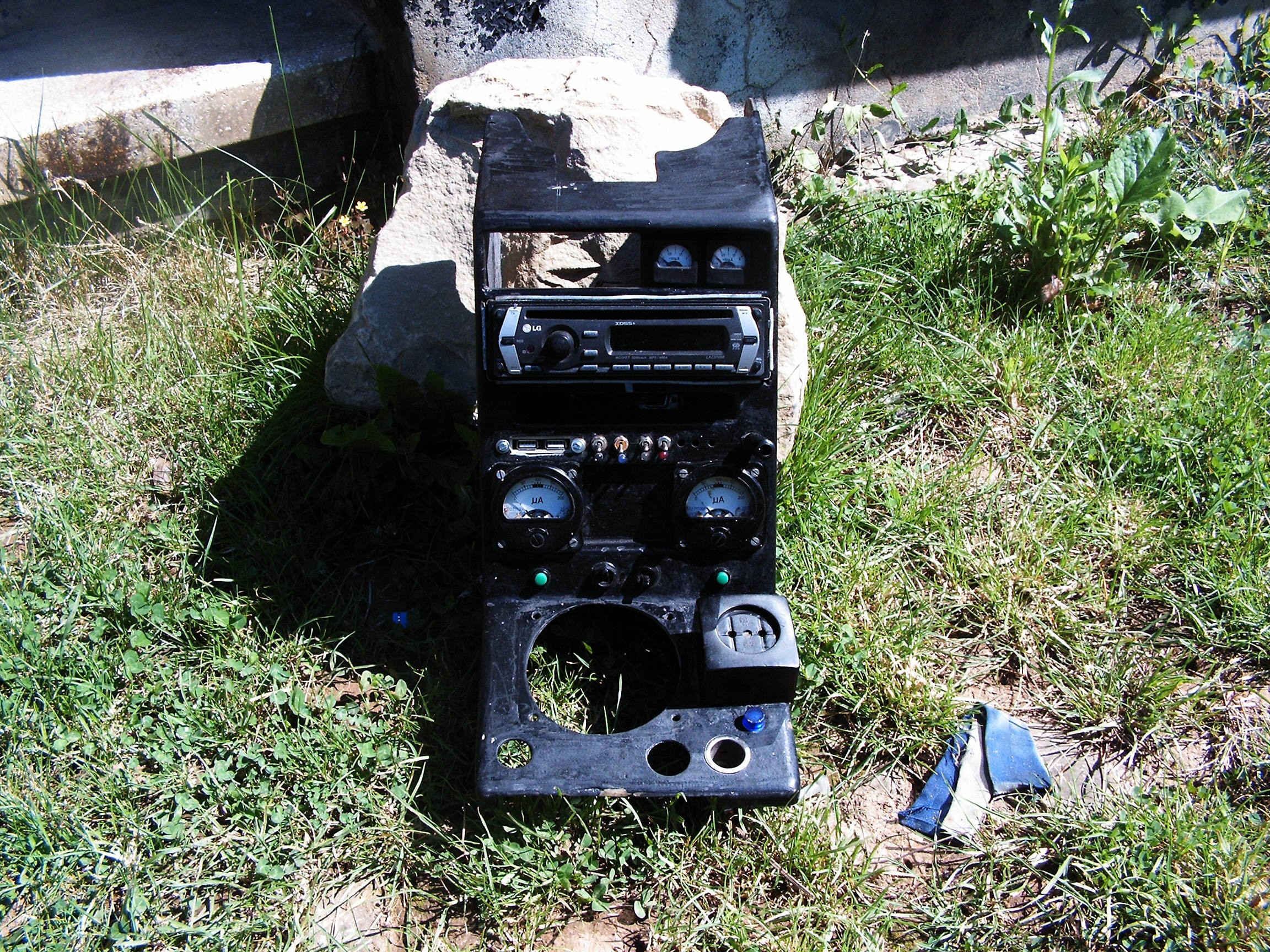
Input stage, equalizer and 12V to +/-24V inverter installed. That DB37 connector is responsible with system power up and speaker outputs.
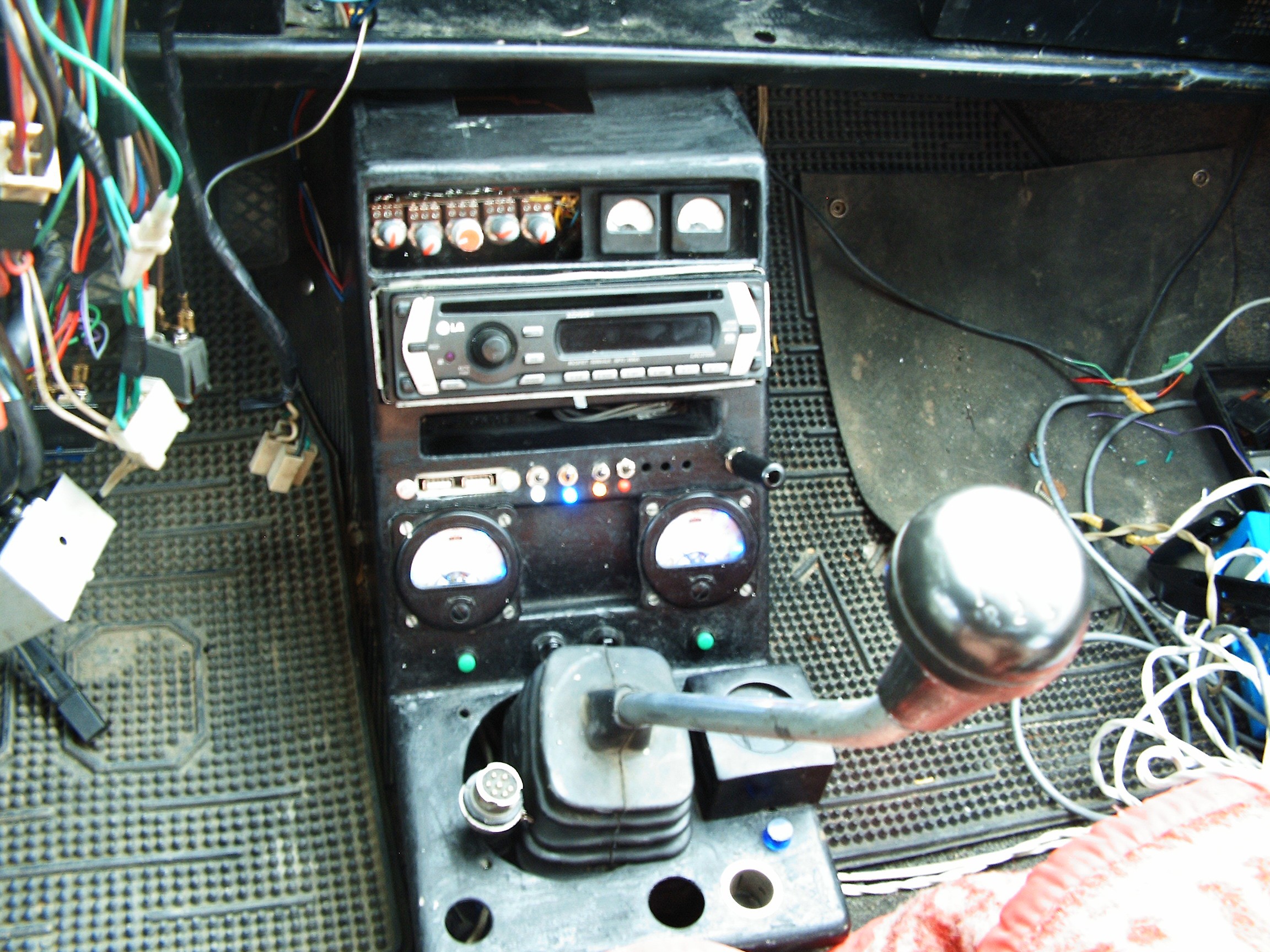
Some small CRT tube should fit nicely in the square between the two big meters. Audio graphic analyzer oscilloscope-type.
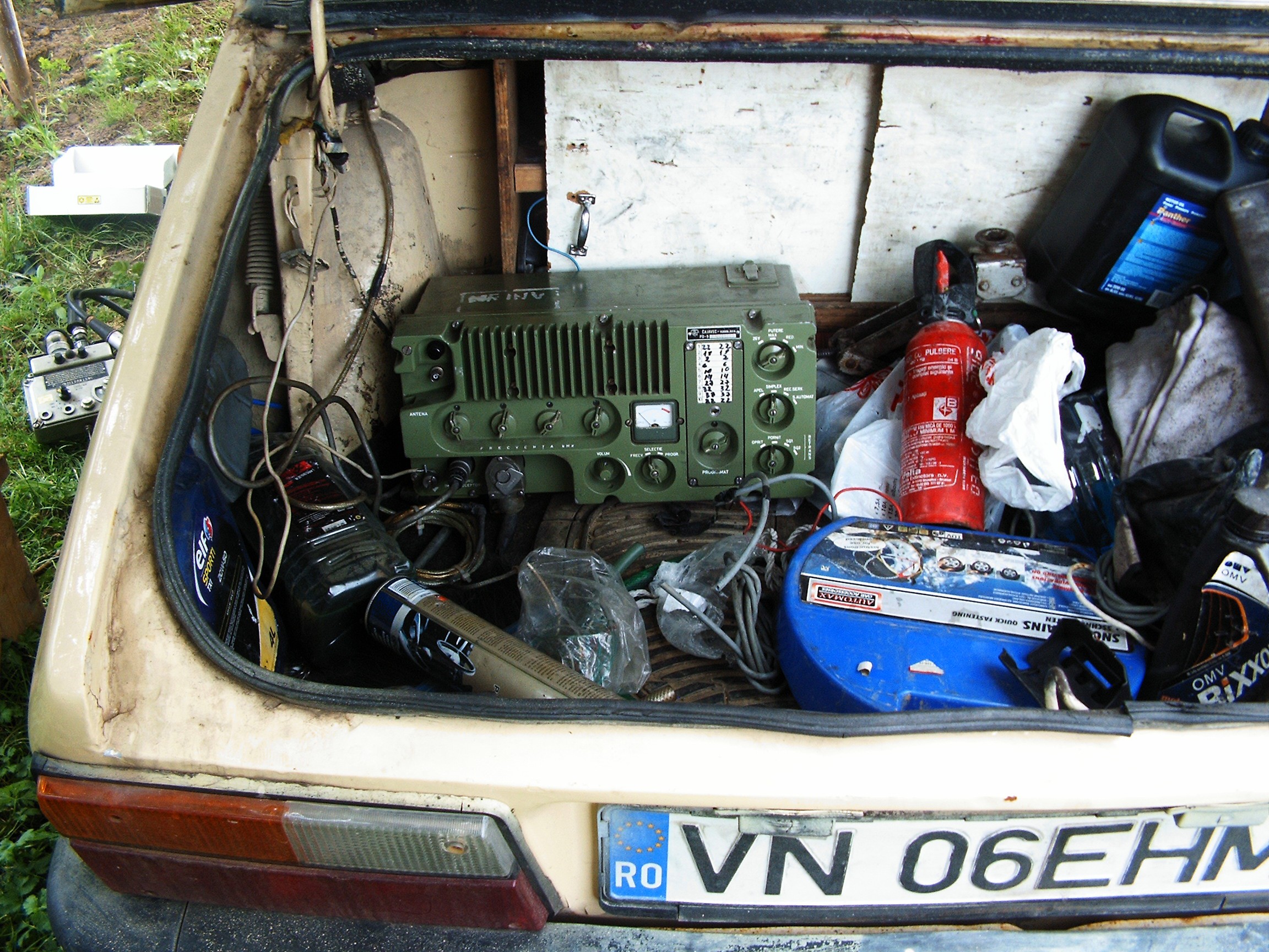
Next log - detecting radiations.
[END OF TRANSMISSION]
______________________________________
kernel panic: improbability coefficient below zero
Discussions
Become a Hackaday.io Member
Create an account to leave a comment. Already have an account? Log In.