 [skaarj]
Good Morning and welcome to the 4th edition of [skaarj]'s Science Time log.
Today we are going to review the analysis results using the rebuilt/repaired gas chromatographs described in the previous log. The experimental setup is described, and a set of results is discussed.
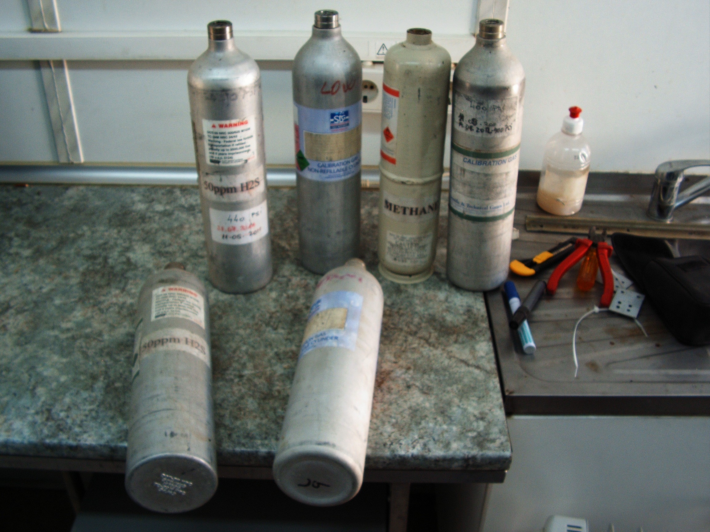
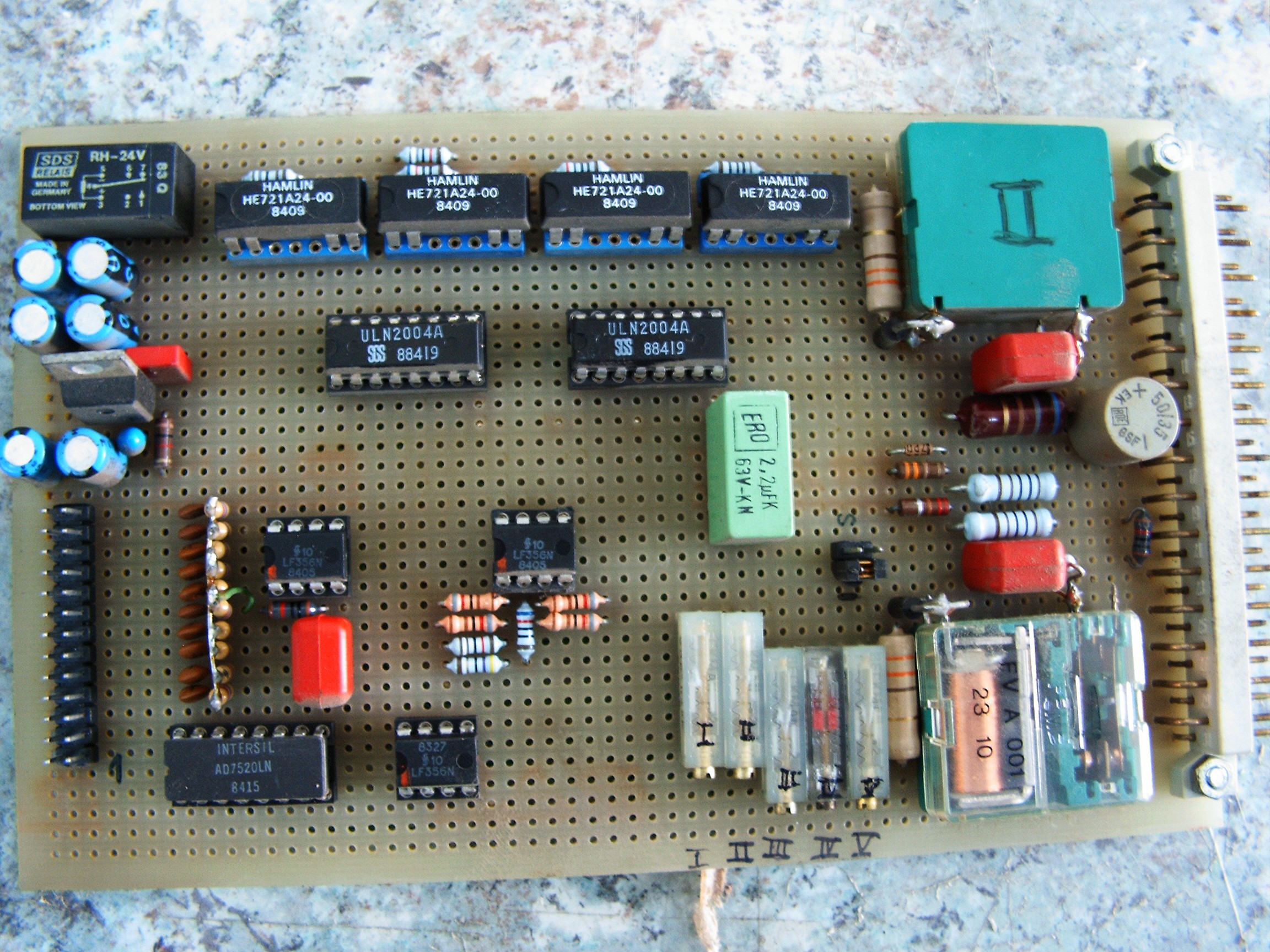
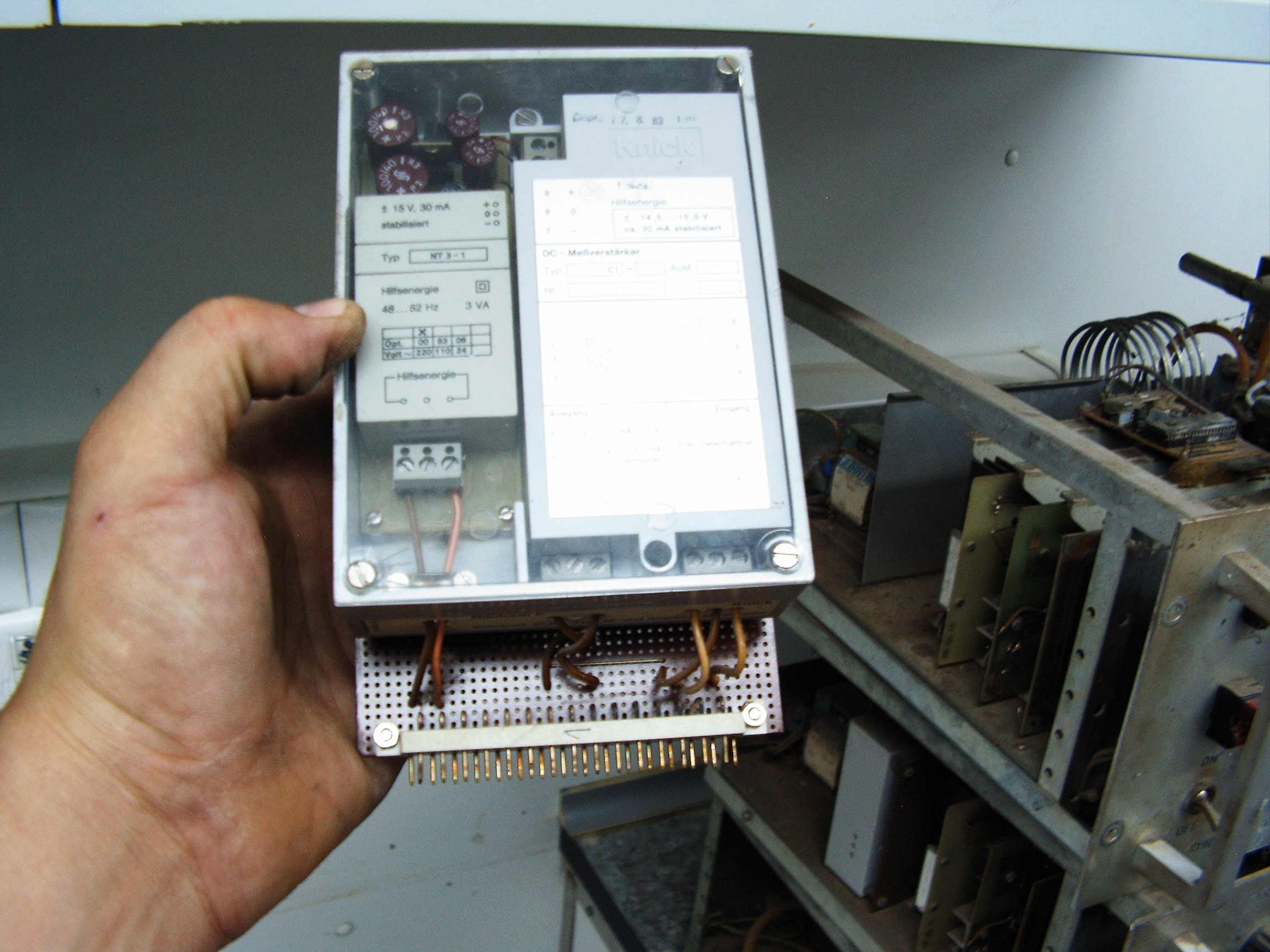
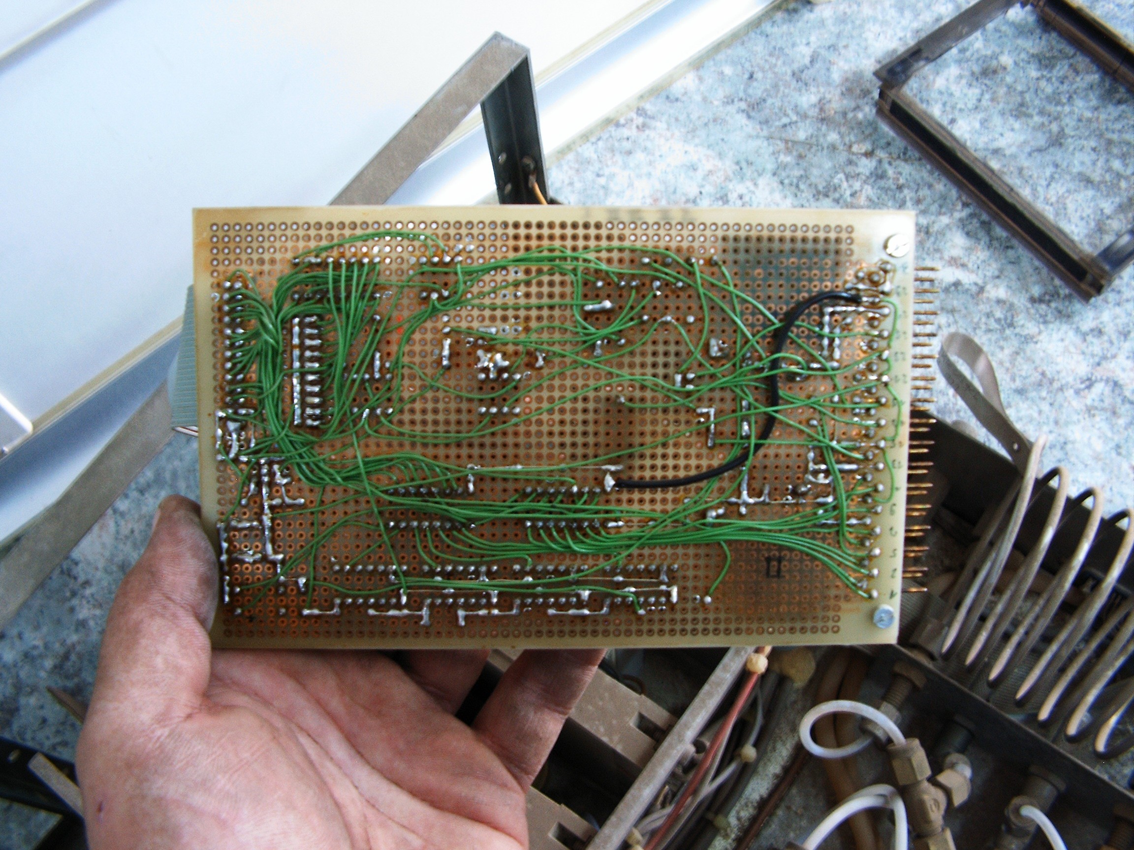
From the beginning we have to set the things clear. At first I almost started to believe that my planned Citizen Scientist approach for this project failed for good. Somehow the Divine laughed at me and said something like "Let there [skaarj] hack his way out of this" and I was given the Chromatograph, and the rest of the story is known. The device is "calibrated" using expired gas calibration tanks, it was rebuilt in a hurry using questionable methods such as FID to TCD conversion plus electronic parts and wires found in the drawers. Rats and humidity tampered with most of the wiring and - most important - there is A LOT OF NOISE in the output signals and the precision of this monster is unknown.
1. Experimental Setup
For the beginning, this is the block schematic of the proposed Exhaust Gas Analysis system.
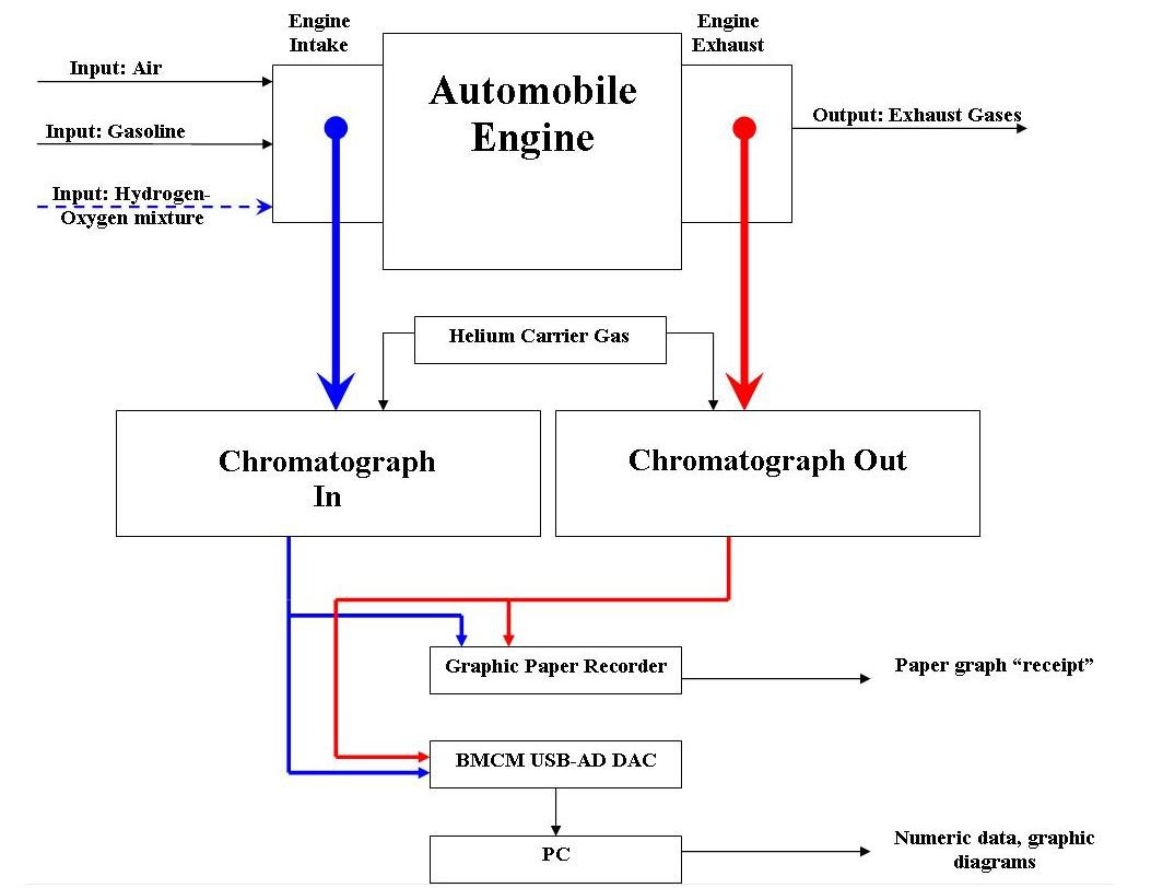
This is my proposed block schematic for presenting a generic gasoline ignition engine and my way of tampering with it. Carburetor stays on top of the intake manifold and performs the air-gasoline mixture. Additionally there is a hydrogen-oxygen gas source which is mixed with the air.
Input mixture goes into the engine, but there's a small hose (blue color in the figure) going to the first Chromatograph unit (Chroma In).
A small part of the exhaust gases is extracted through a second hose (red color in the figure) going to the second Chromatograph unit (Chroma Out).
Both of them perform the gas analysis as described at the beginning of the previous log.
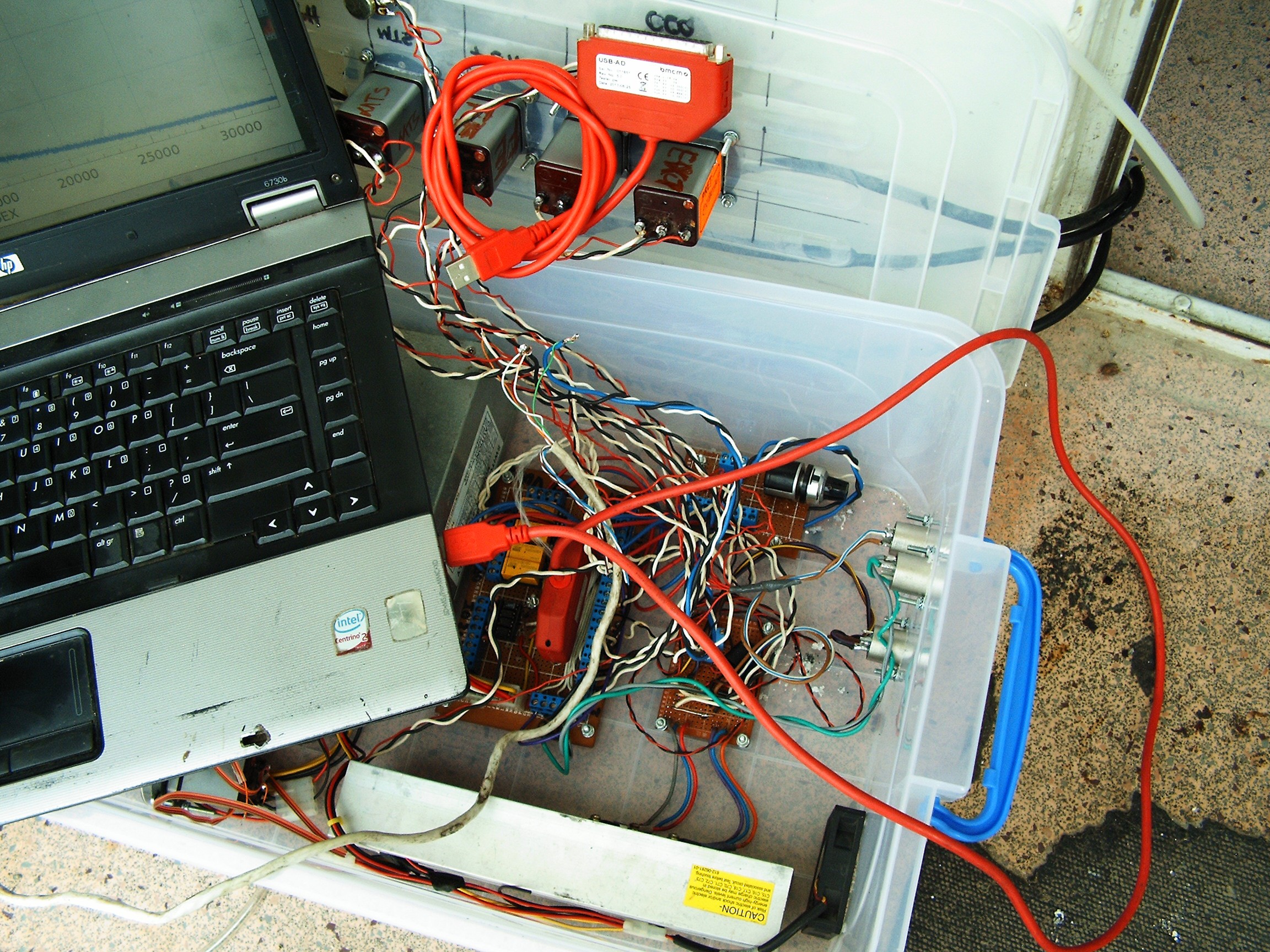
Output signals from both Chromatographs are connected to both the paper graphic recorder and a data acquisition card connected my old laptop to dump all the numbers.
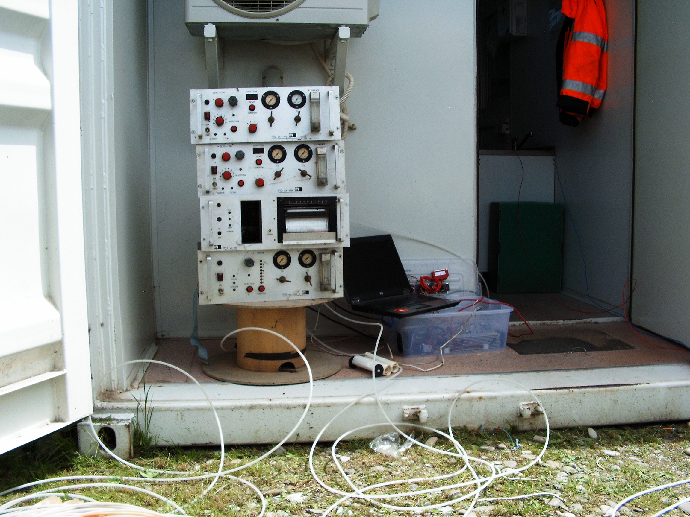
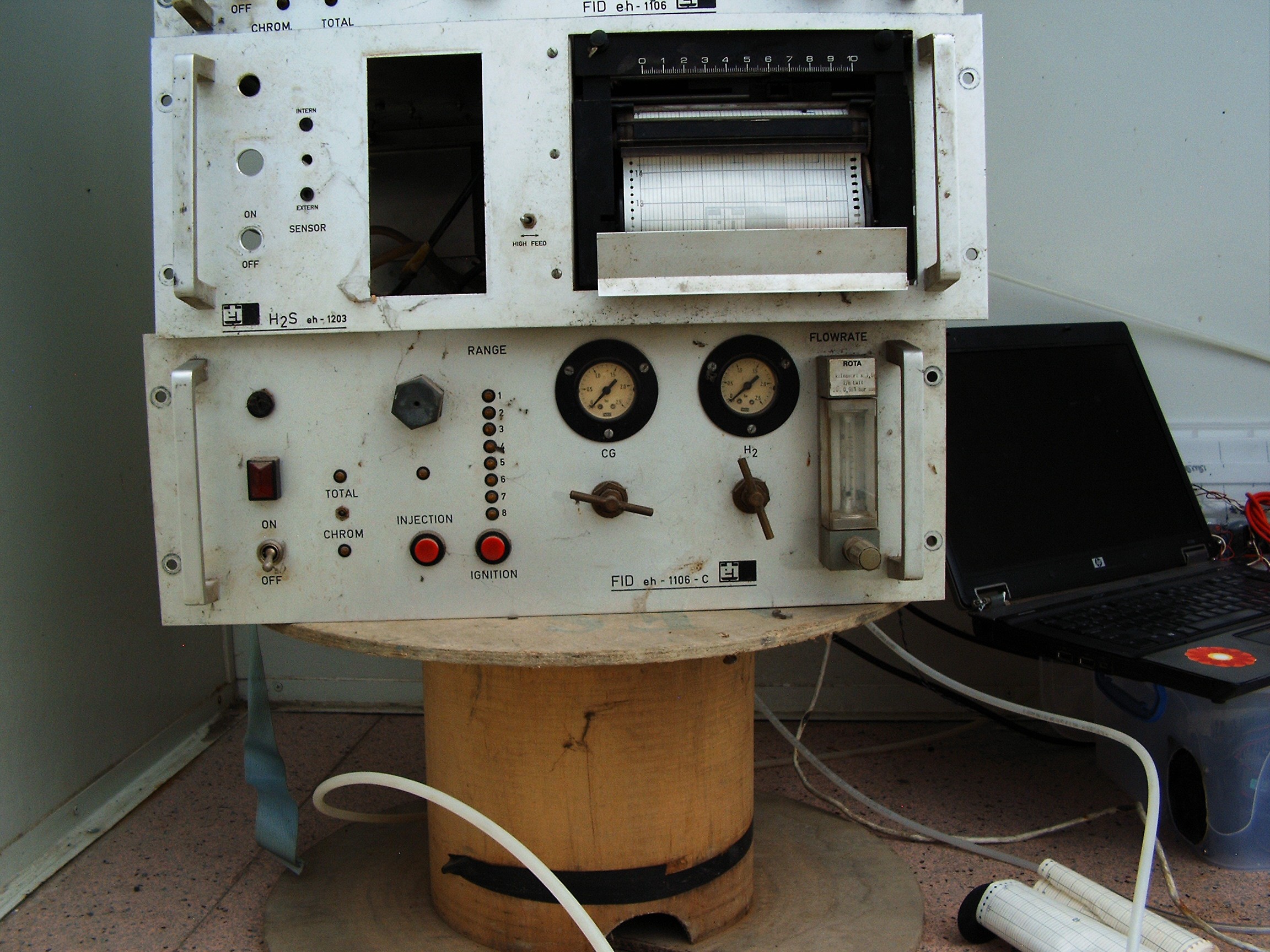
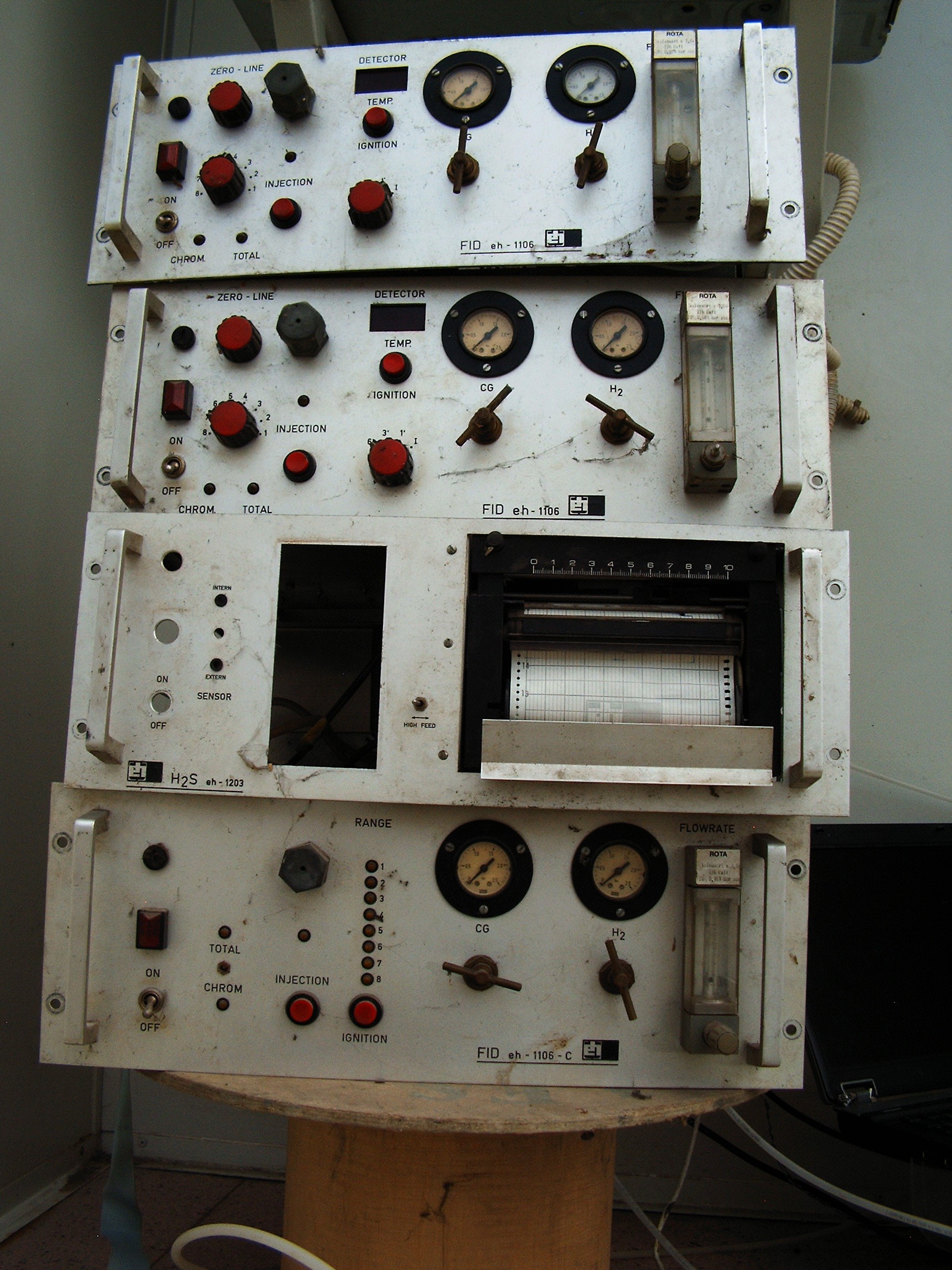
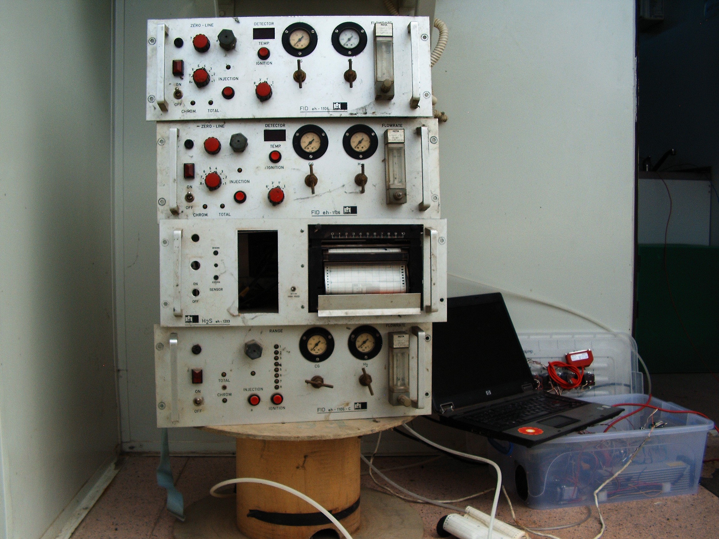
From left to right, top to bottom:
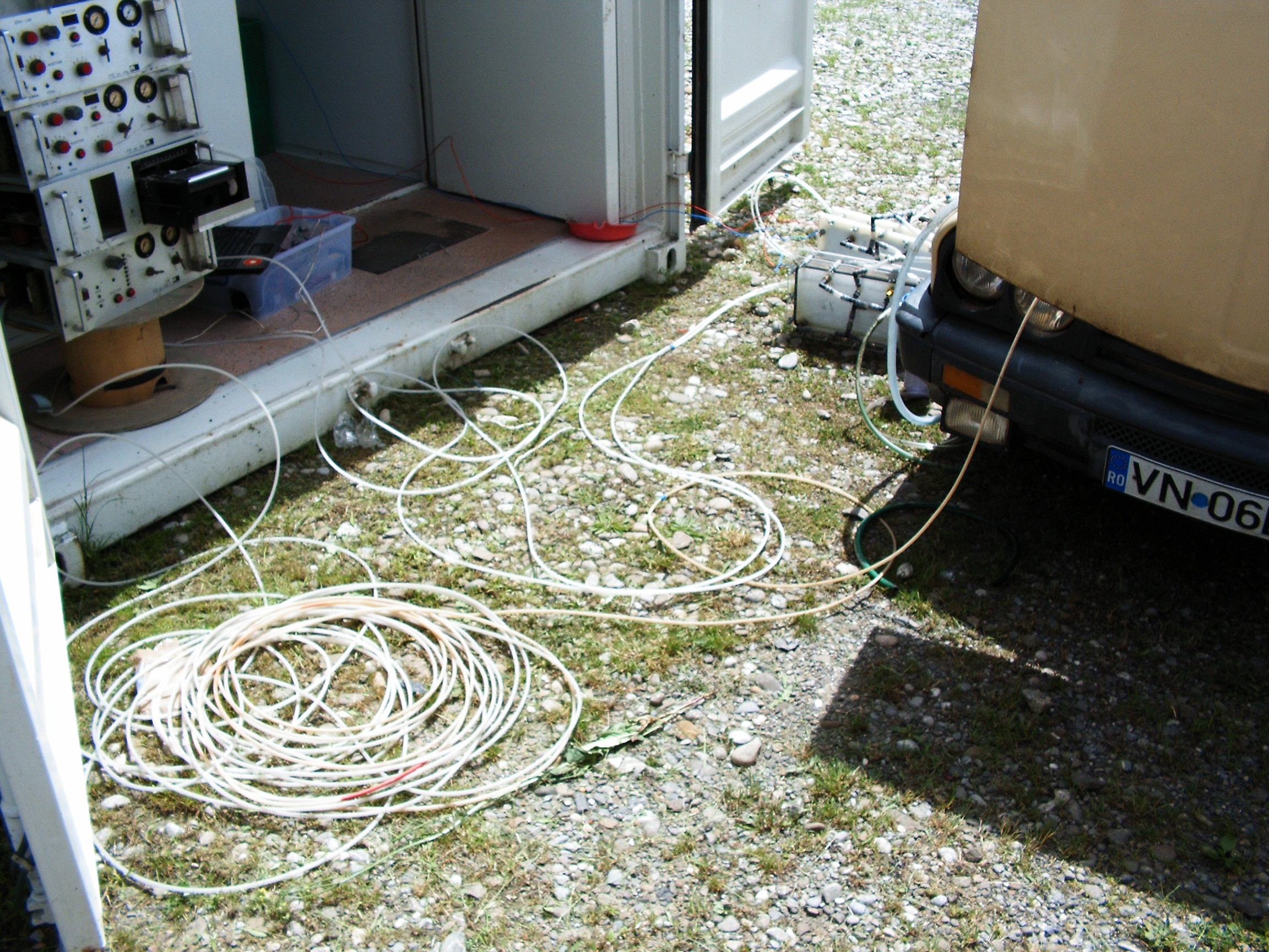
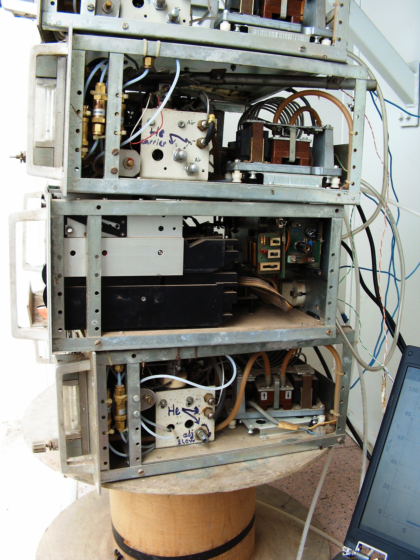
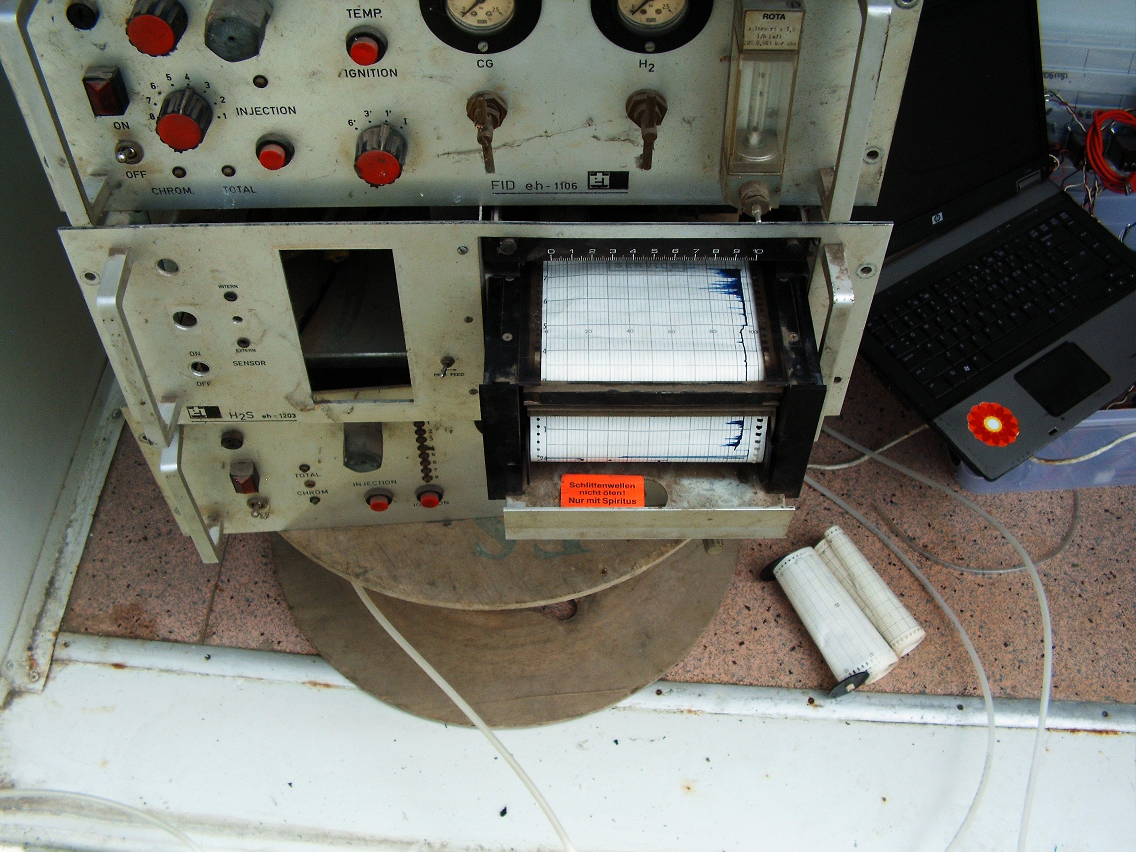
1. Chroma In, Chroma Out, Paper Graphic Recorder (no paper), Spare Chroma;
2. Hose in the left: air intake line; hose in the right going to the back of the car: exhaust line;
3. Those two strange things near the right side container door: hydrogen electrolysis reactors;
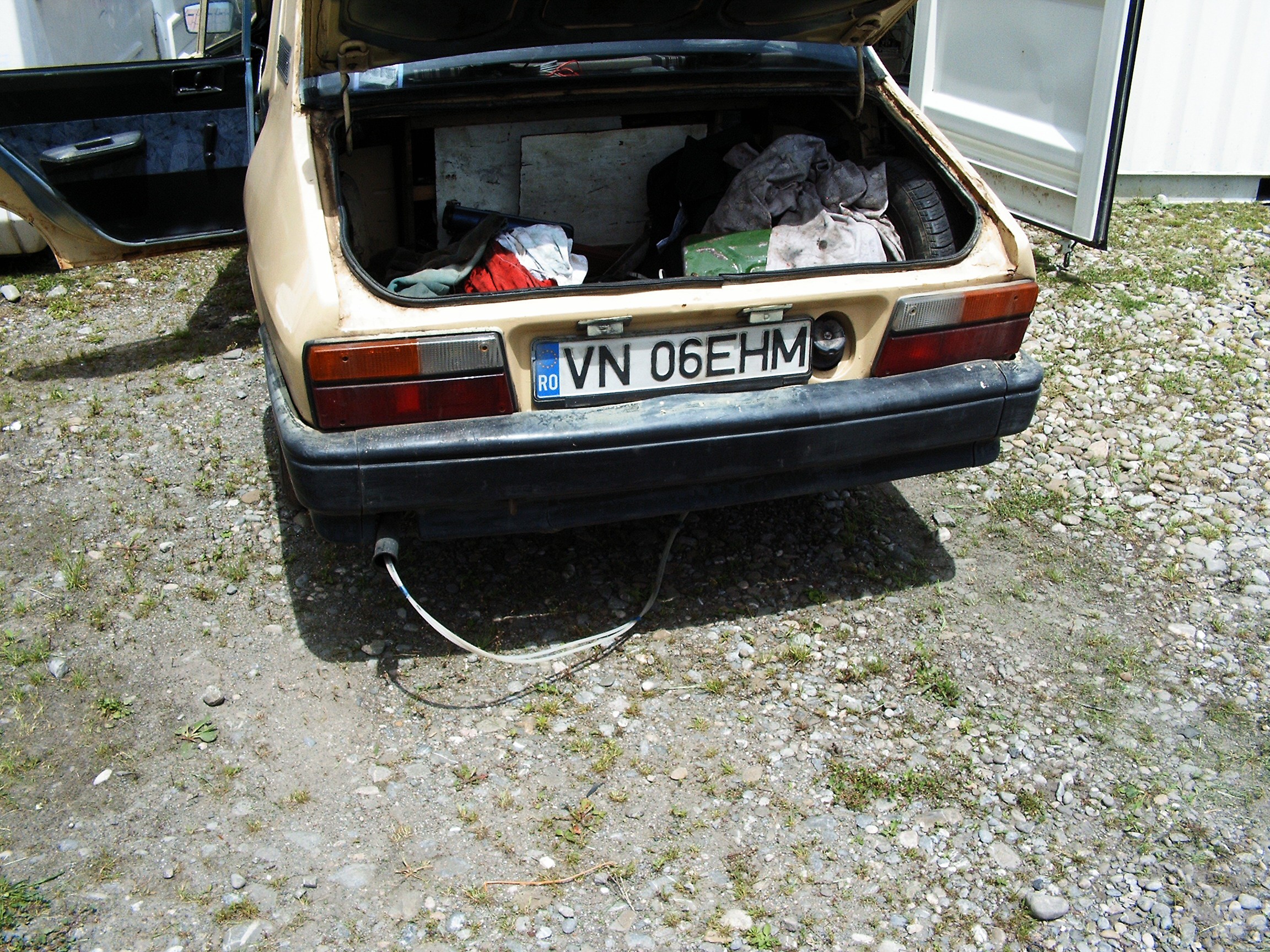
4. Dacia 1310MLS, made in 1986, engine capacity 1297cc, maximum speed (when wind blows in the rear) 100km/h; time to reach from 0km/h to 100km/h: around 10 minutes; engine pollution factor: SKY HIGH.
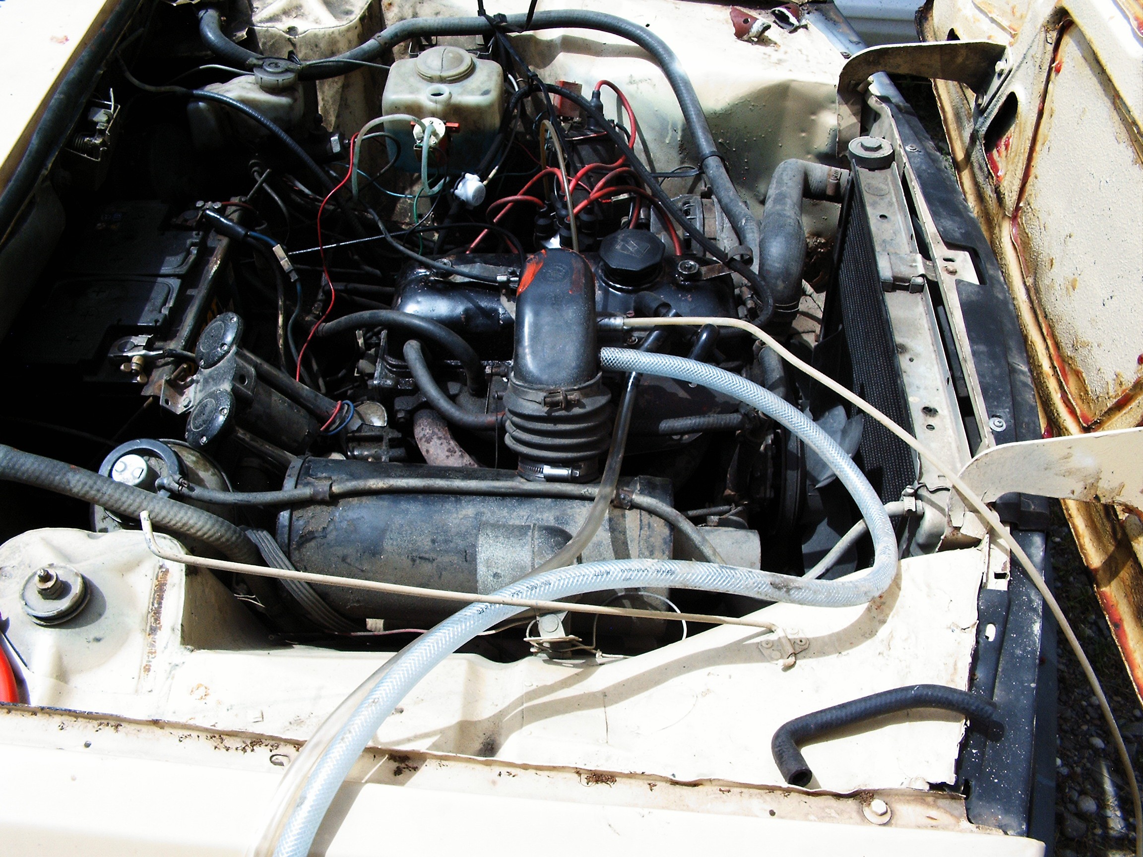
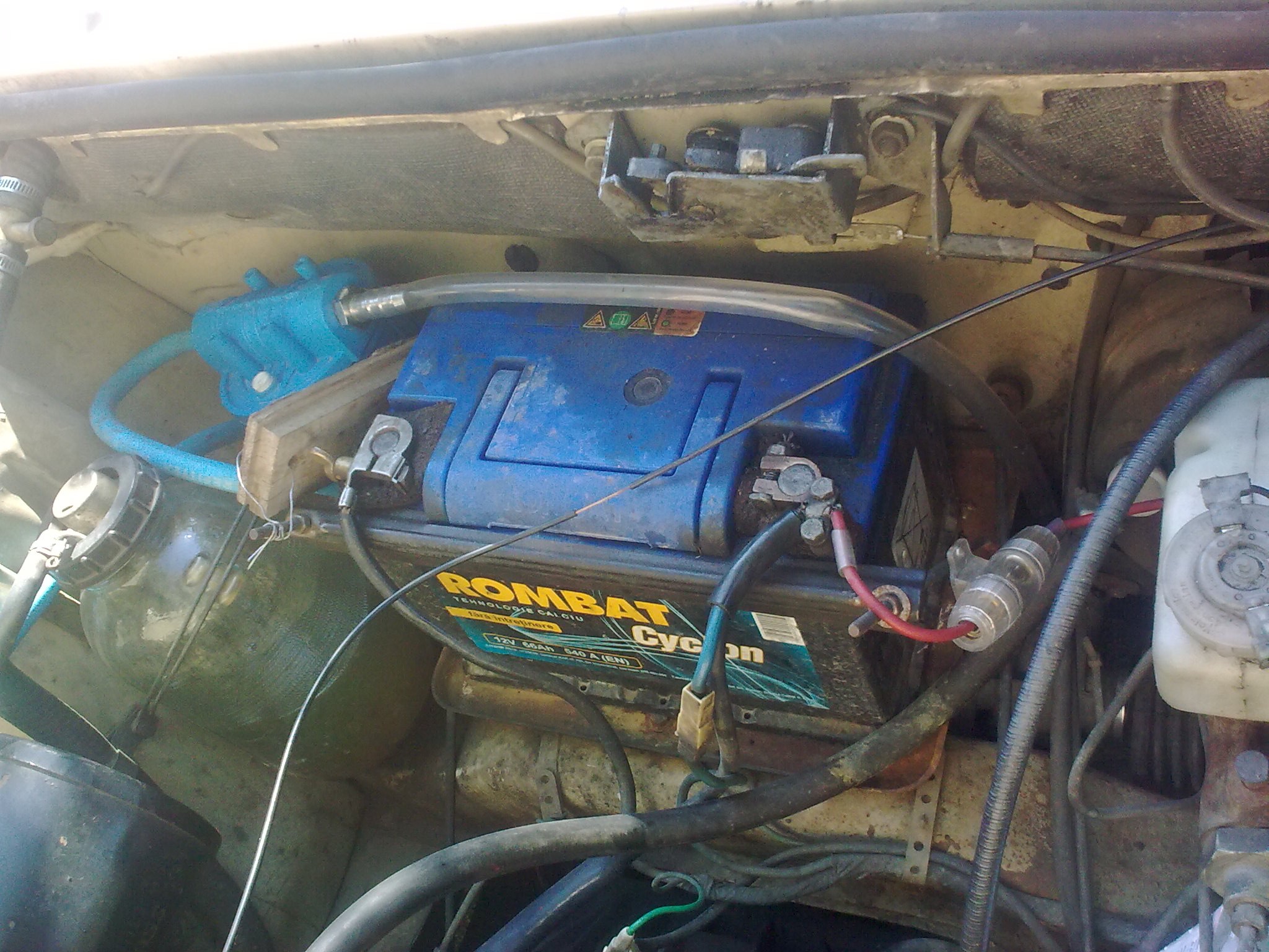
Dacia 1310 engine. Still looks nice and still doing its job after so many servicing years.
Big hose - hydrogen from first electrolysis reactor connected to air intake hose (black thing curved like a glove);
Big transparent hose - hydrogen from second electrolysis reactor, connected directly to engine air intake manifold under the carburetor;
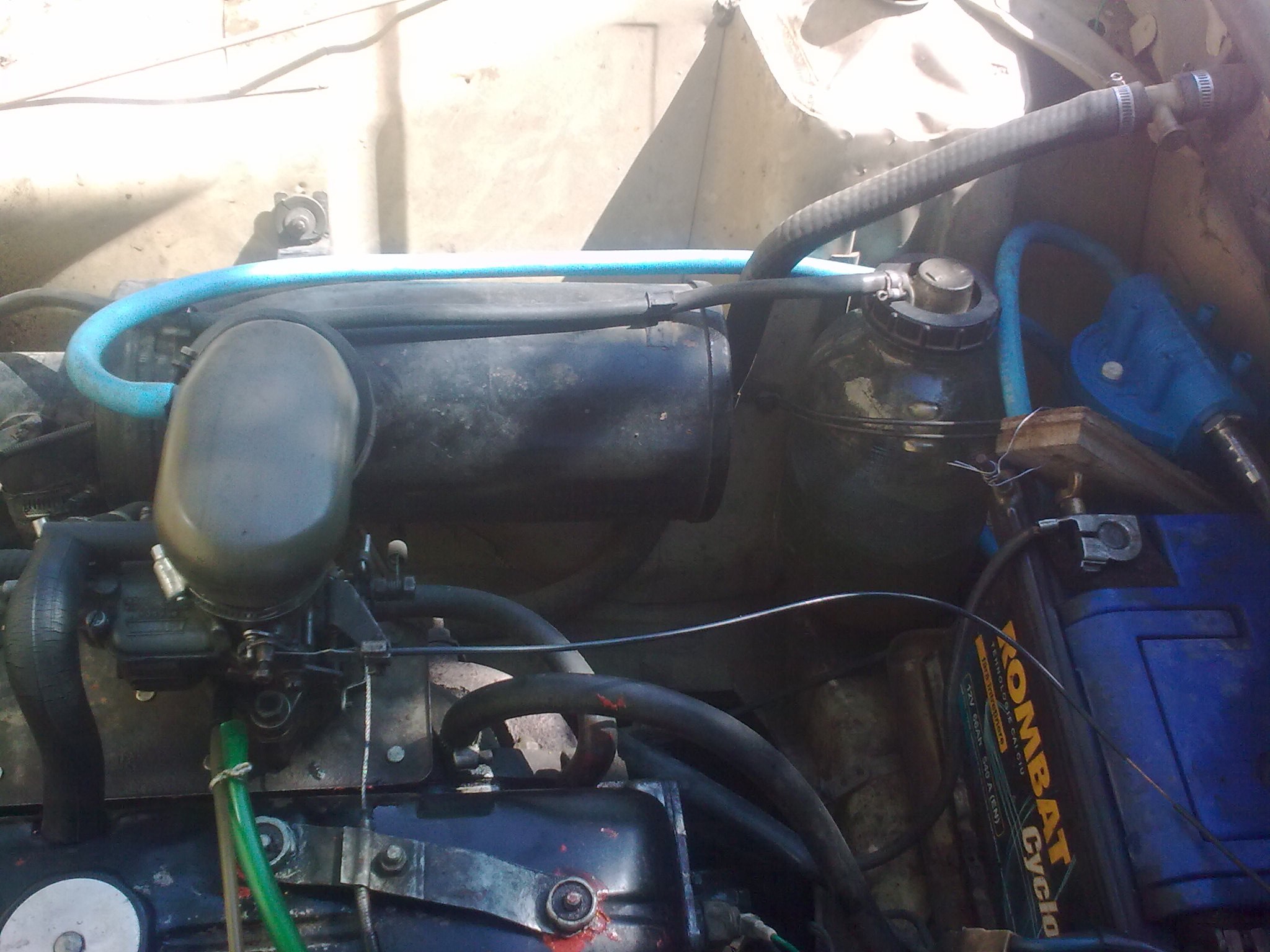
The big black round cylinder (bottom side) is the air filter. In its left side there is a glass receipt containing the coolant (distilled water). Air intake hose sits on this cylinder, and the other end covers the carburetor air intake.
That red paint on top of the air intake hose is liquid silicone covering a big hole.
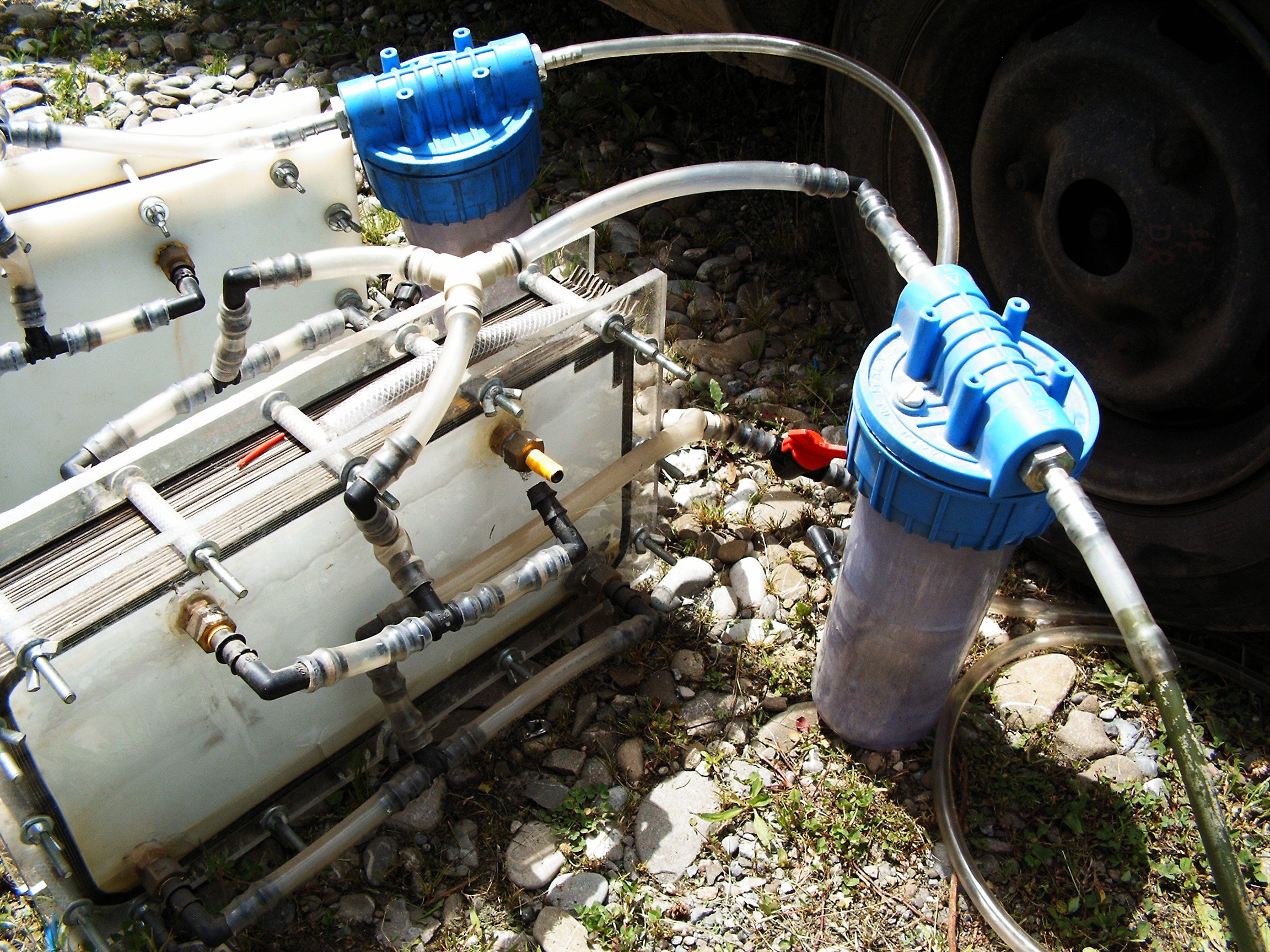
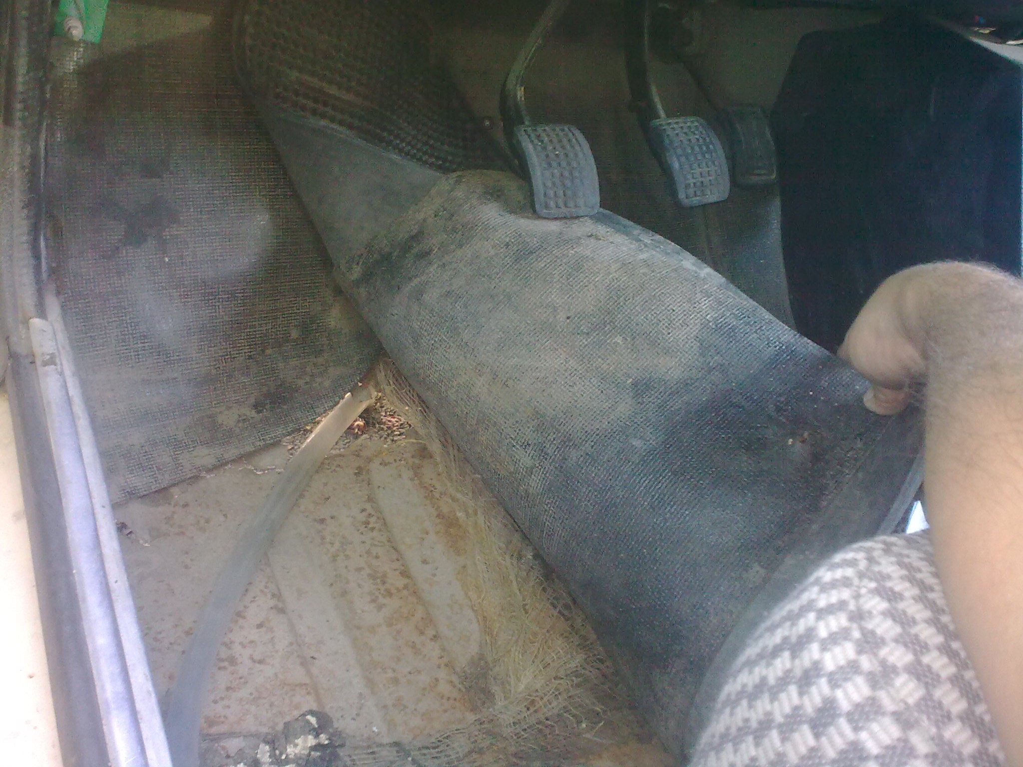
Small white hose near the hydrogen hose: Chroma In Gas Line.
Two hoses inserted in the exhaust pipe. Those are going to Chroma Out.
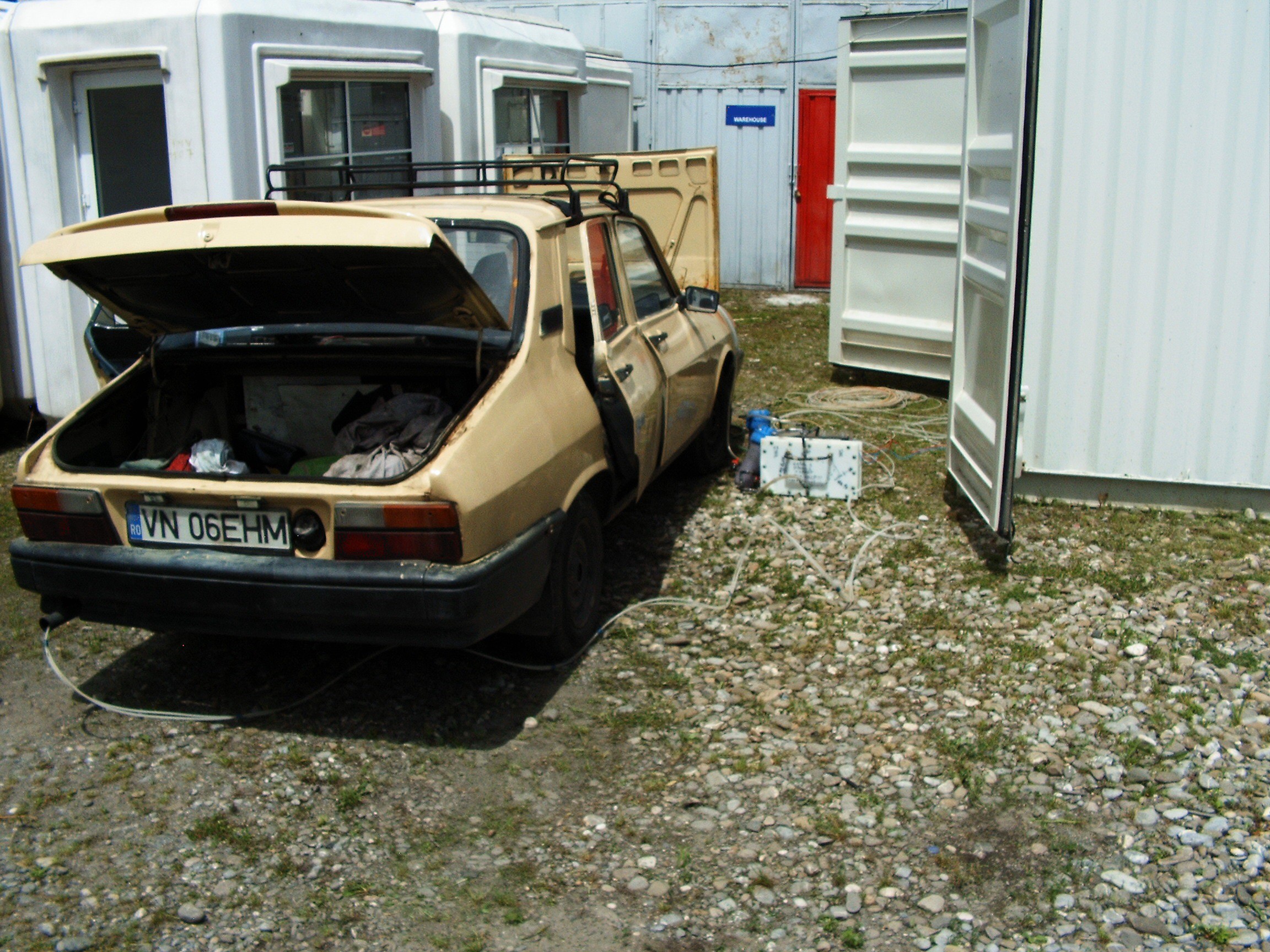
Welcome back to the Madhouse. This time we get to visit the yard.
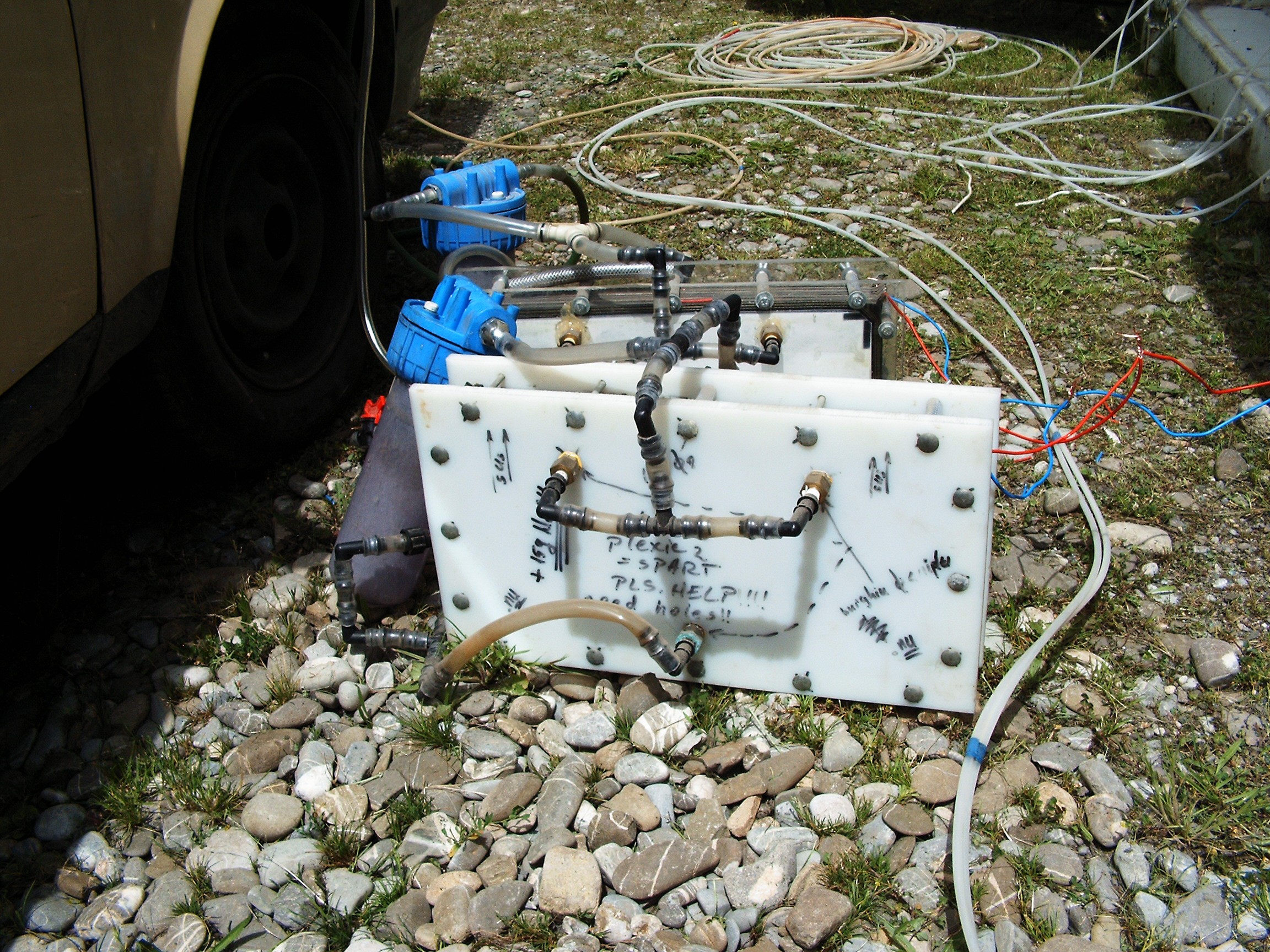
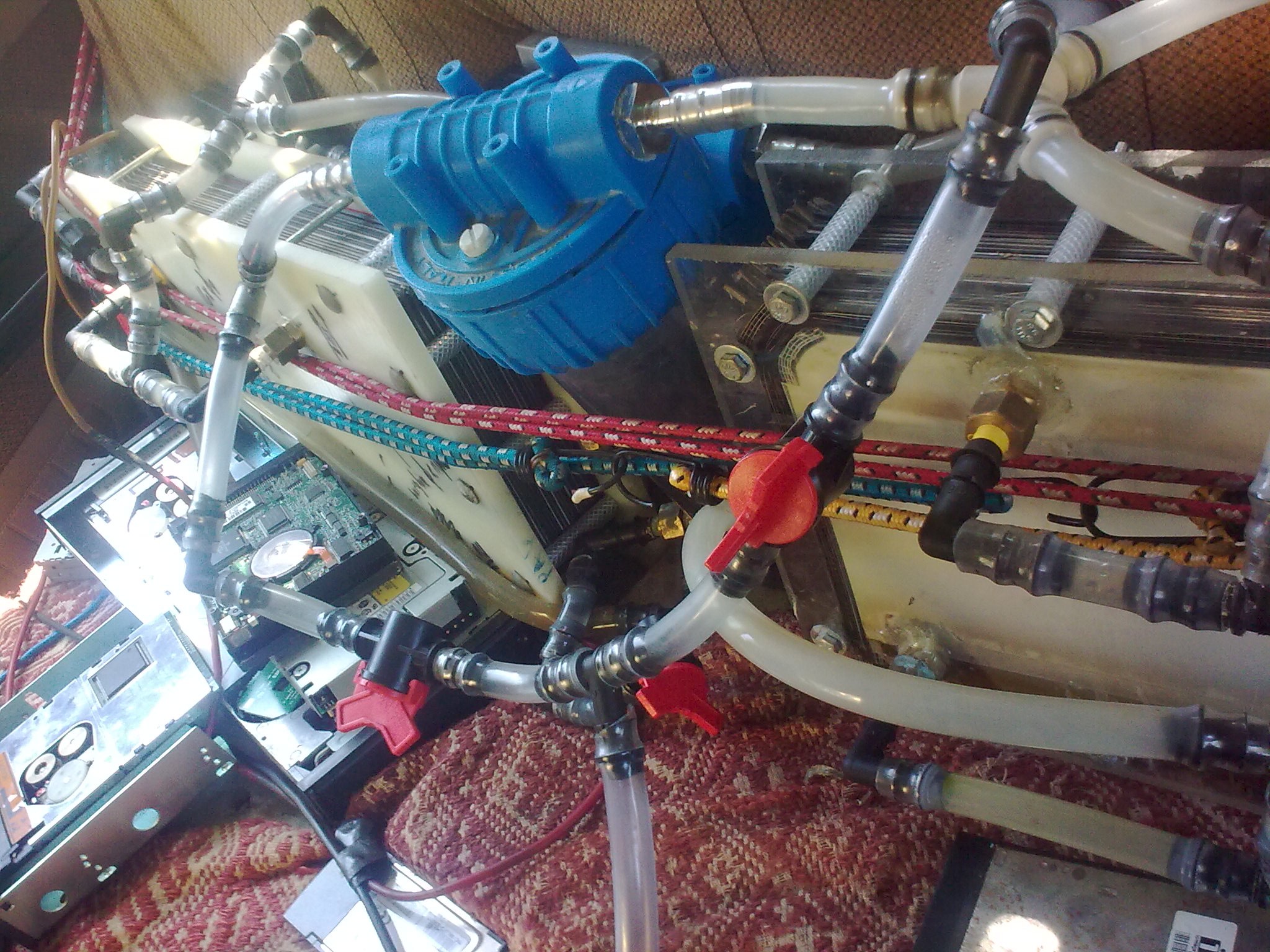
Hydrogen Electrolysis Reactors
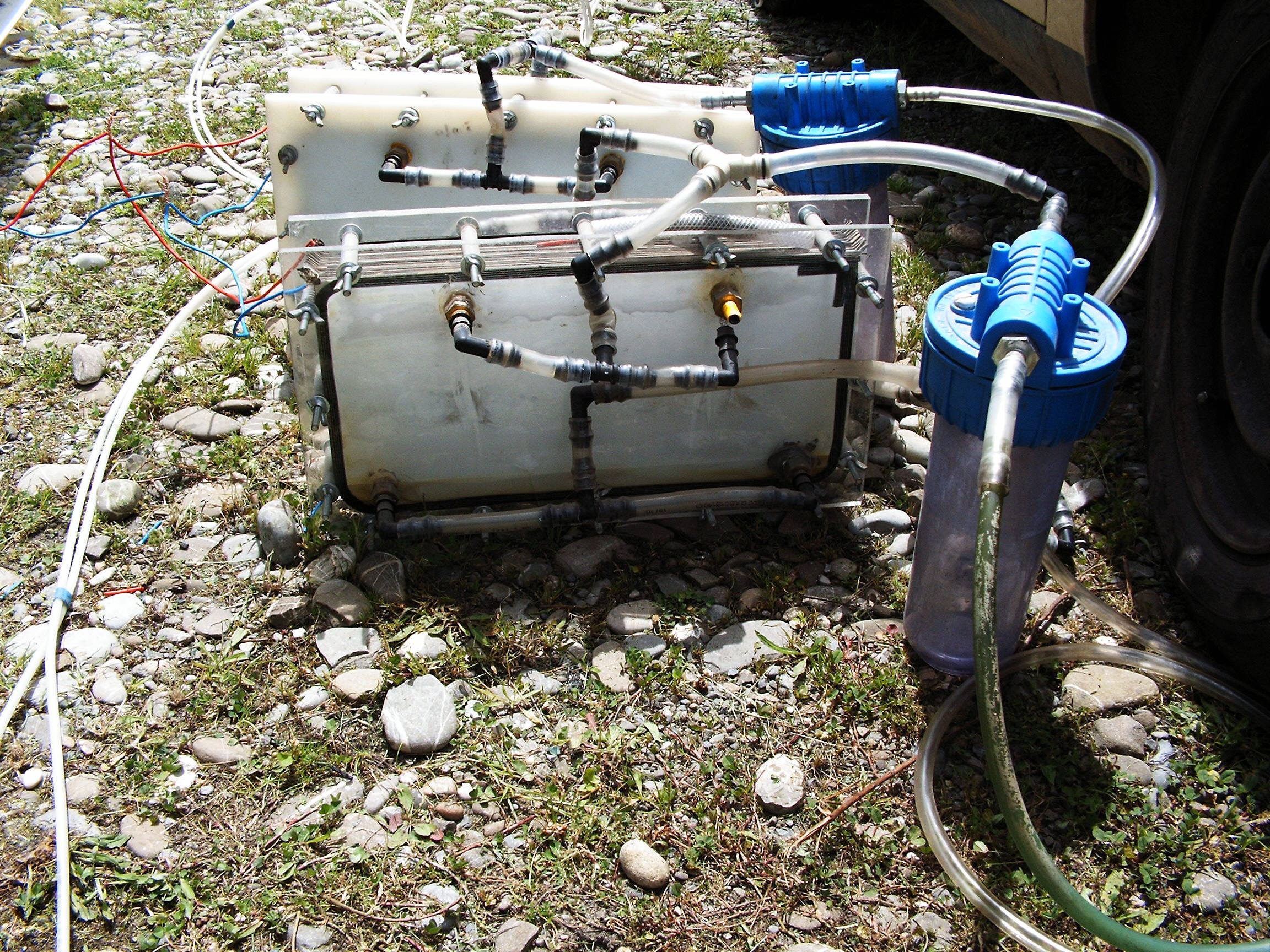
Construction and functionality of these electrolysis reactors is described in Science Time (II) log.
As described in the Science Time (II) update log, each reactor output is protected with a bubbler filled with distilled water. Unfortunately I do not have any spark arrester, so in case of a reverse spark - the flame will stop inside the bubbler at water surface. This is a safety measure. If those bubblers are not present and there's a reverse spark happening, those reactors can EXPLODE.
Pulsing the reactor with variable voltages - as some myths on the Internet suggests - did not show any increase in hydrogen flow. So 220 volts rectified.
As you may notice, on the transparent reactor there's a disconnected hose. There is also one disconnected on the other reactor. That's because I want the hydrogen to go streight out in the open while the powered reactors reach the proper temperature - I don't want more than 60 degree Celsius, or else steam (from distilled water) will start to come out.
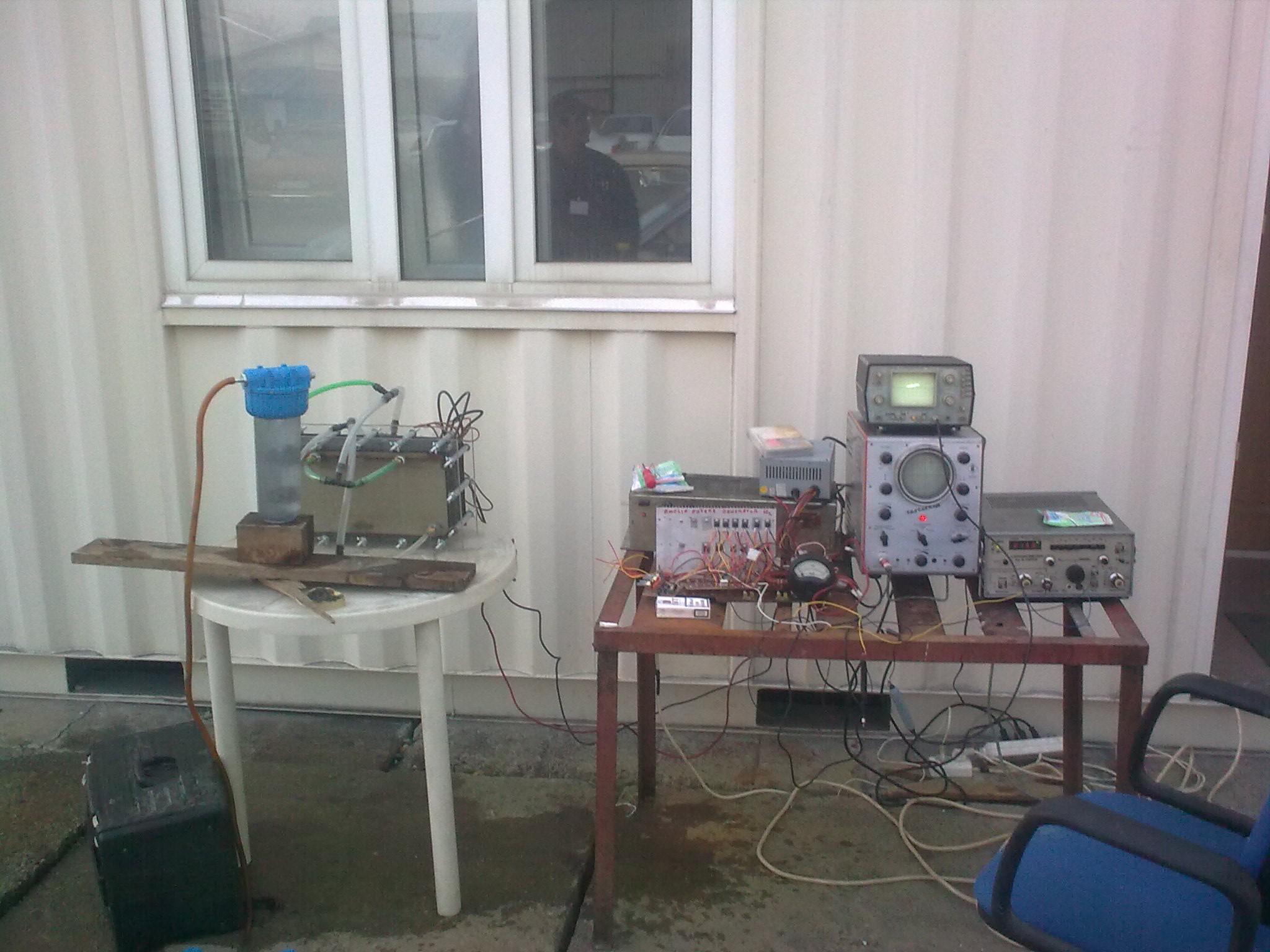
 System powered up and warming. Paper graphic recorded loaded.
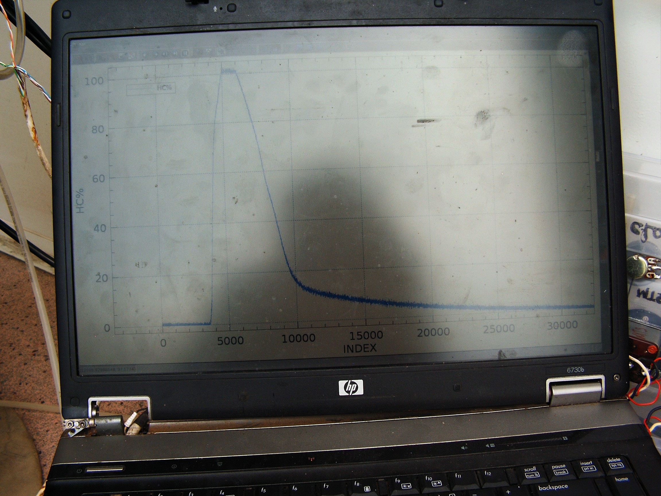
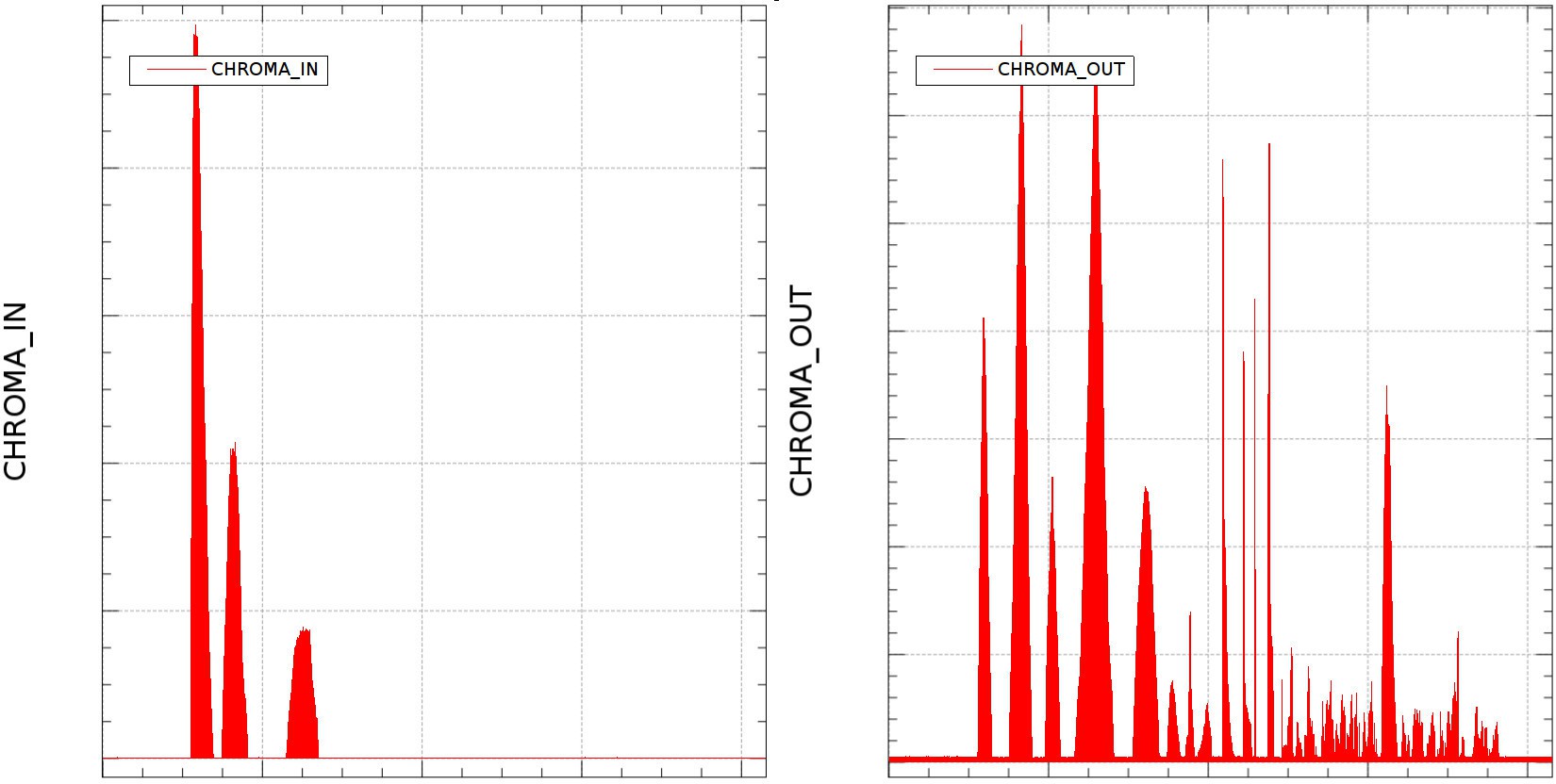
Right side: laptop running FreeBSD and connected to data acquisition unit.
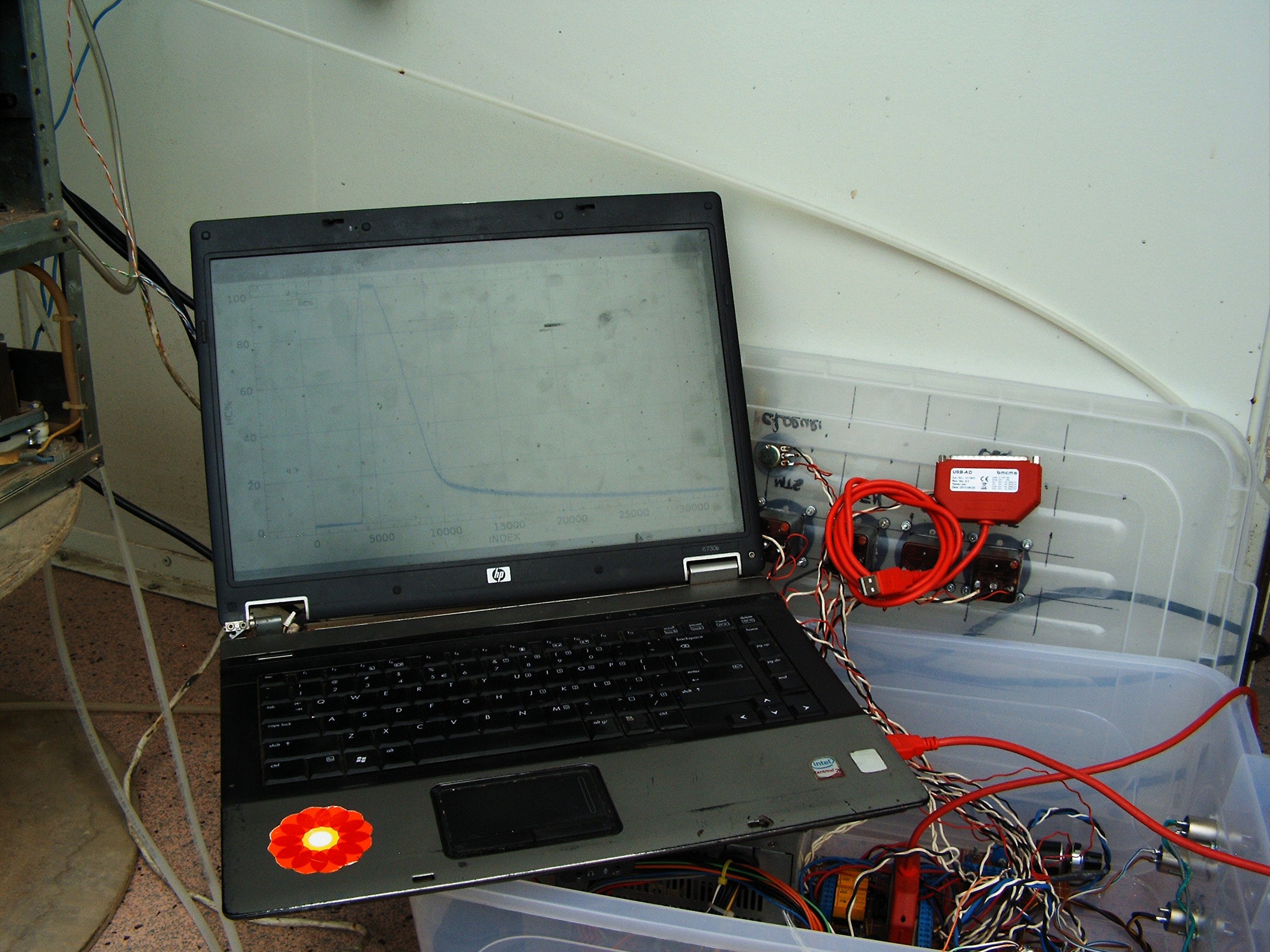
Graphing software on laptop: kst2 + real time data loaded from a file.
C program reads the DAC and outputs numbers in two tab-separated columns.
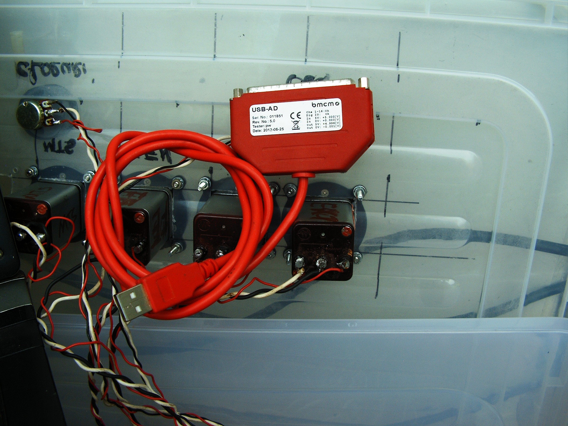
BMCM USB-AD USB Data Acquisition Card. 16 analog inputs, 1 analog output, 4 digital inputs, 4 digital outputs. Works with FreeBSD Unix.
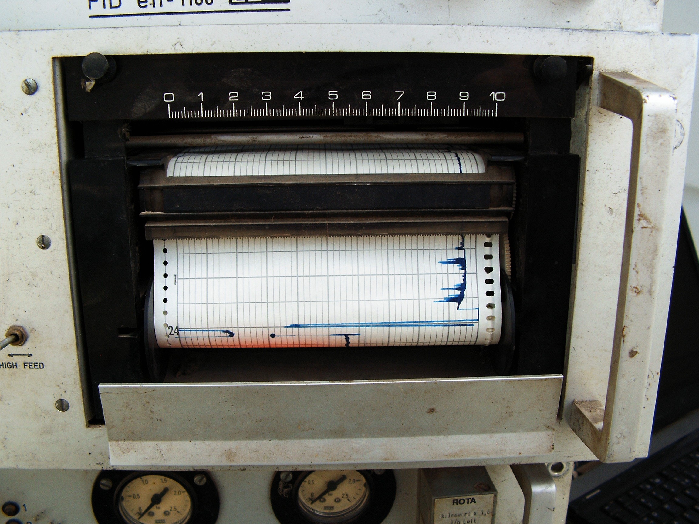
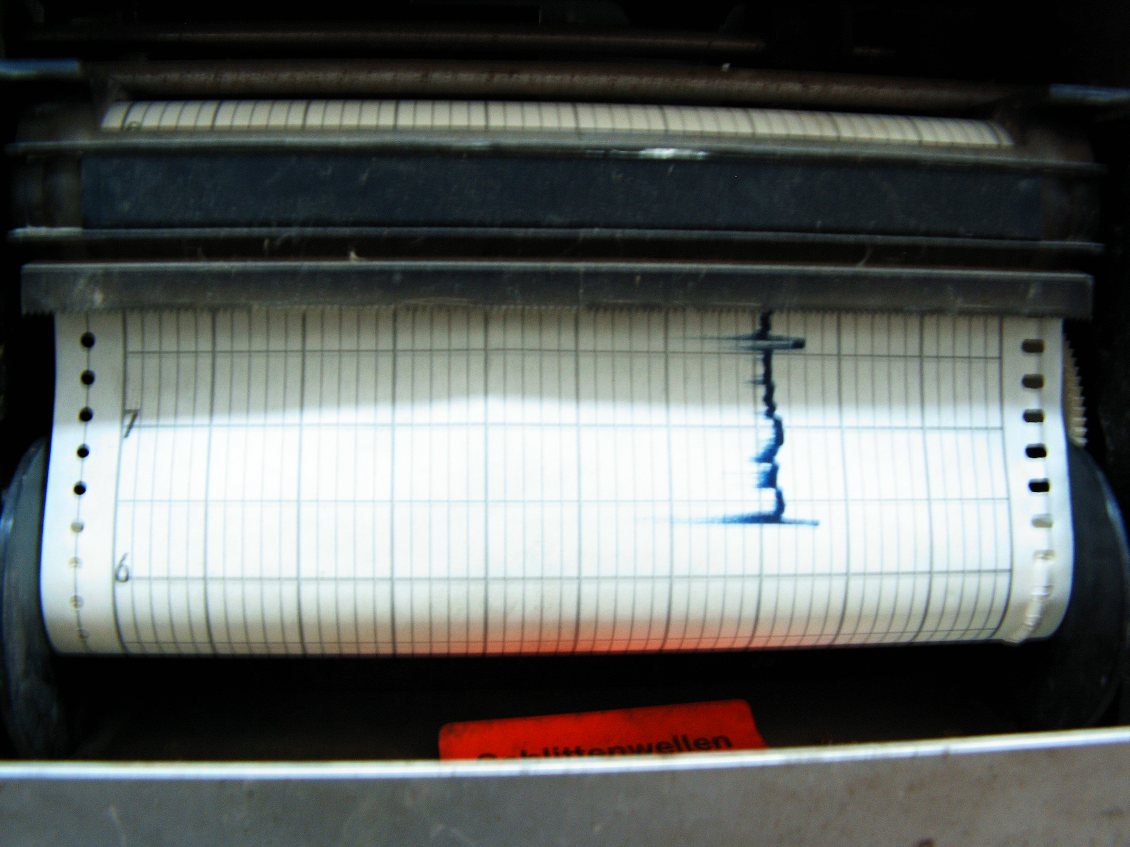
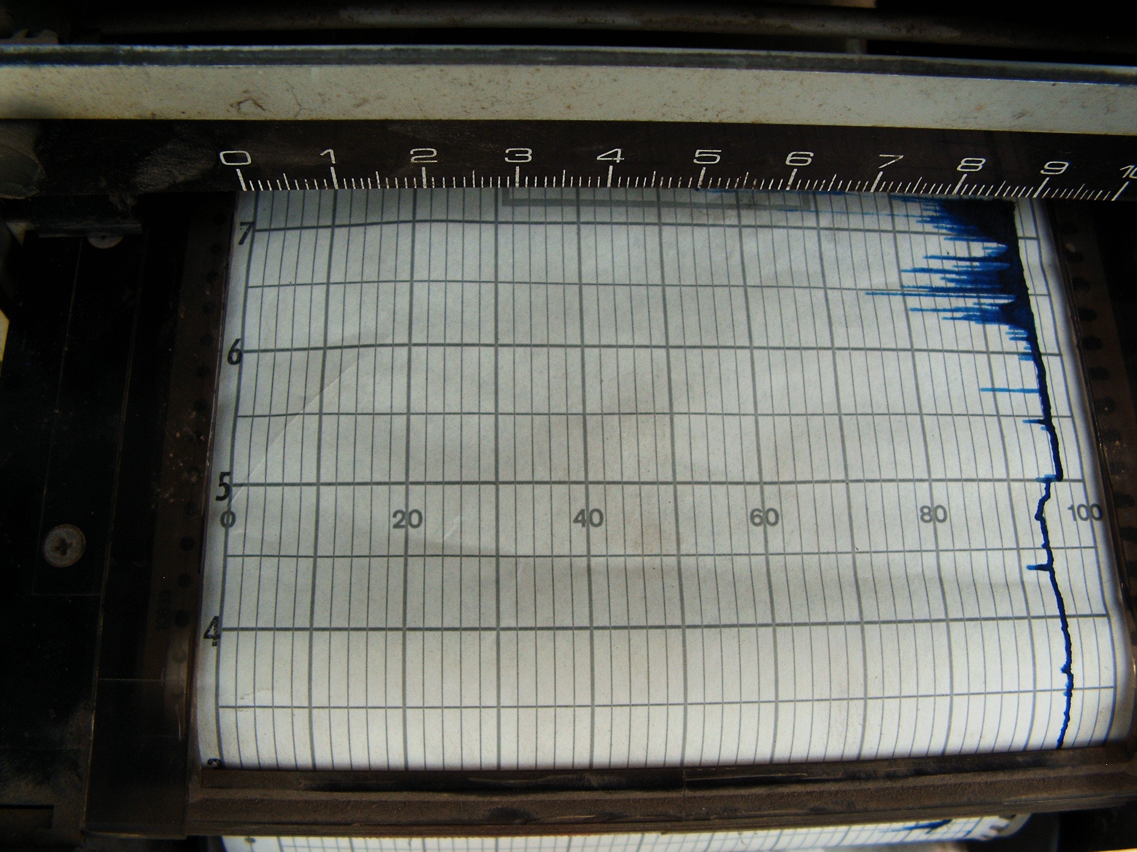
We've got a spike (Air - oxygen, nitrogen) and a lot of noise. After the spike (going from bottom to top) the Chroma says there's a lot of humidity (sudden graph lift-off, slow fall). I think I reversed the polarity of the motor? Graph should start from left side.
Same spike (air) on the laptop. Need to lube the graphic recorder.
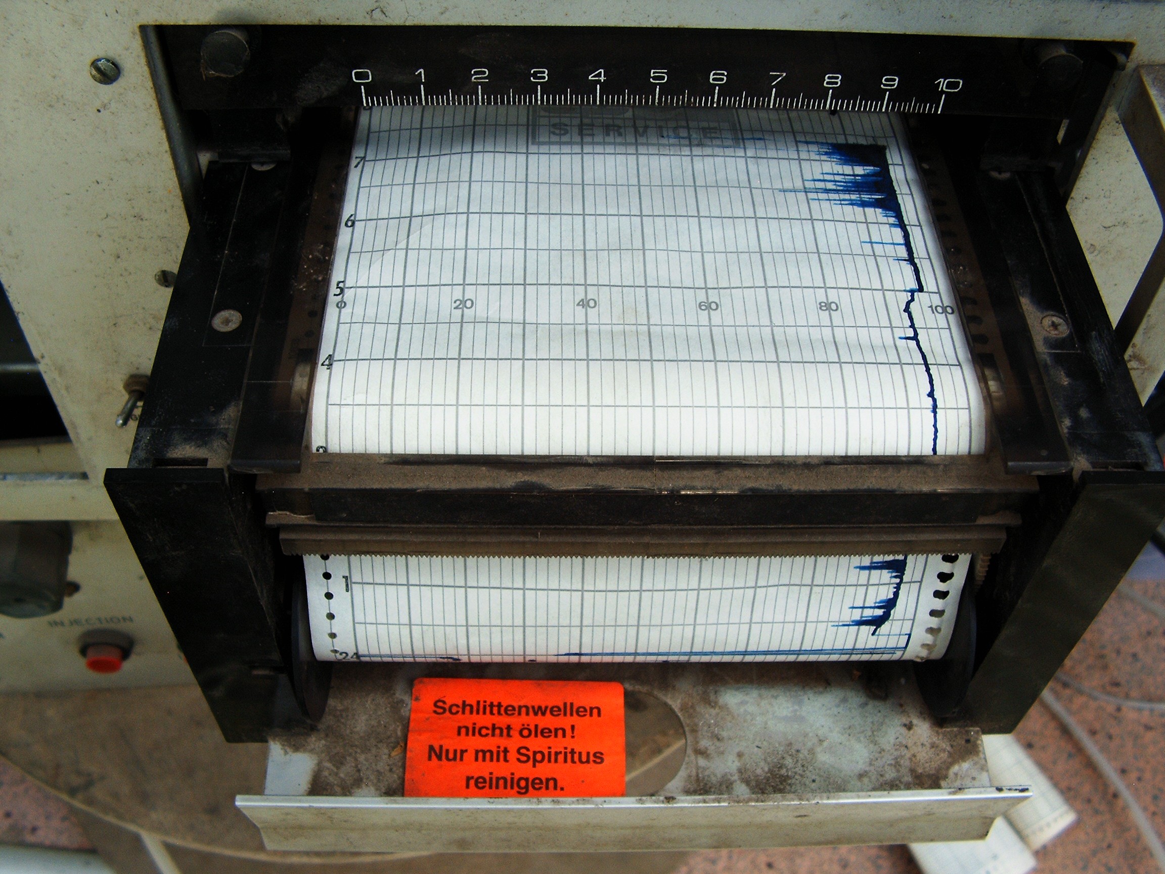
"Do not oil carriage rollers. Clean with alcohol"
System warm-up....
Magic smoke come out from the main board of the graphic paper graphic recorder, but I managed to save the numbers. So no paper receipts for now. I asked a small girl to graph me the results, she needed some extra cash for some computer school project involving data graphing. I gave her the files, now she's taking care of that. So dual graph will be her work. Not the separate graphs in FreeBSD KST2 which are presented for now.
Finally, the car "equipped" with electrolysis reactors:
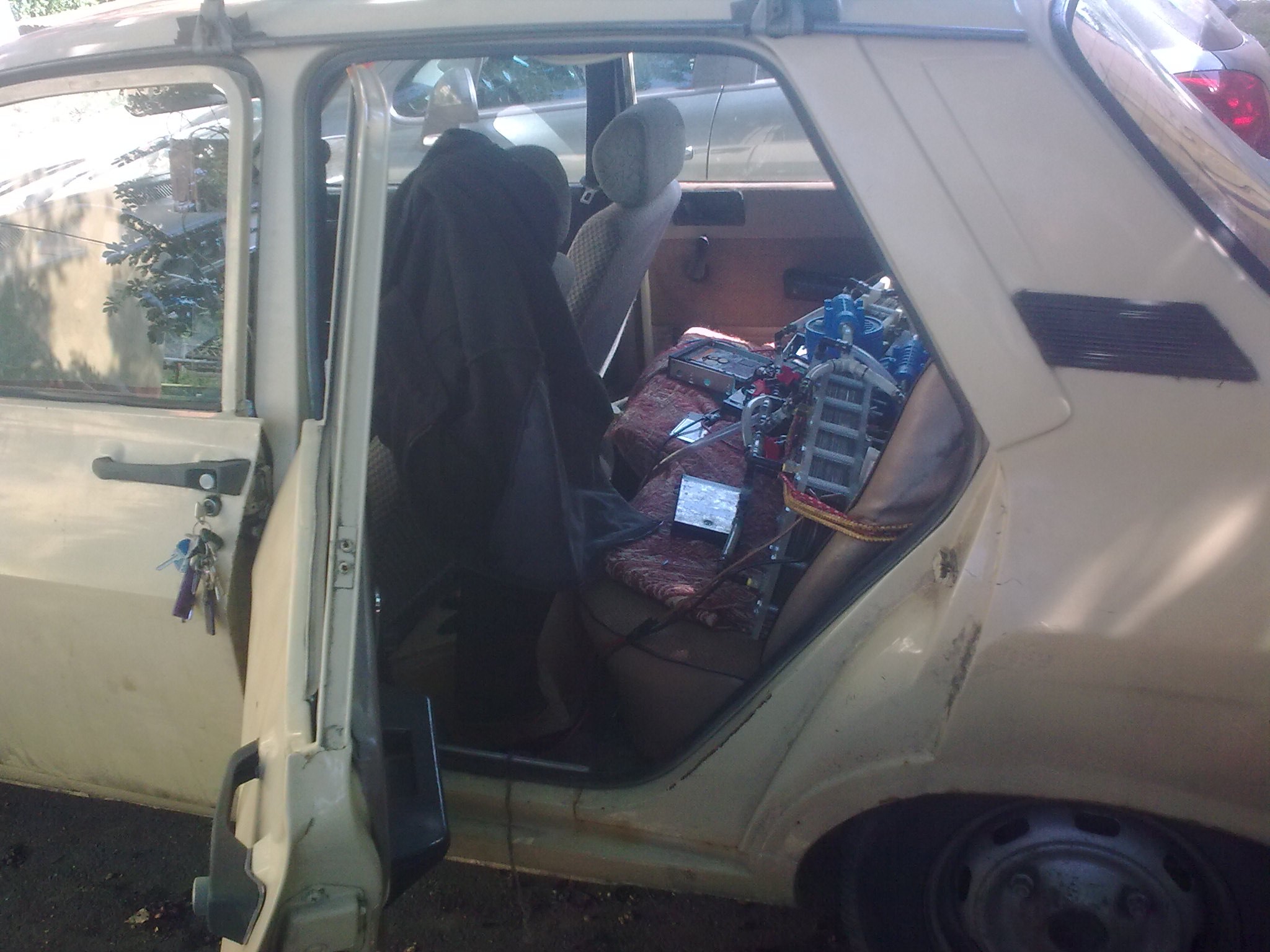
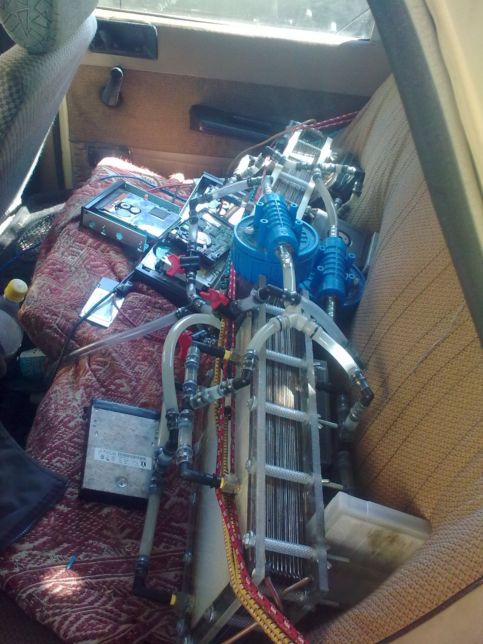
Some hard drives, tape drives and tape cartridges placed to hold everything in place. Those reactors are very heavy, they may break the seat.
Hydrogen-oxygen hose goes out through a hole under driver's feet....
and through a third final bubbler streight into the air intake manifold.
Air intake hose (glove) replaced.
At the base of the carburetor there's the Chroma In gas line.
Need some external electric generator and I can go mobile.
.
.
.
2. Experimental Results
First we need to calibrate both Chromas in order to understand what kind of data they output.
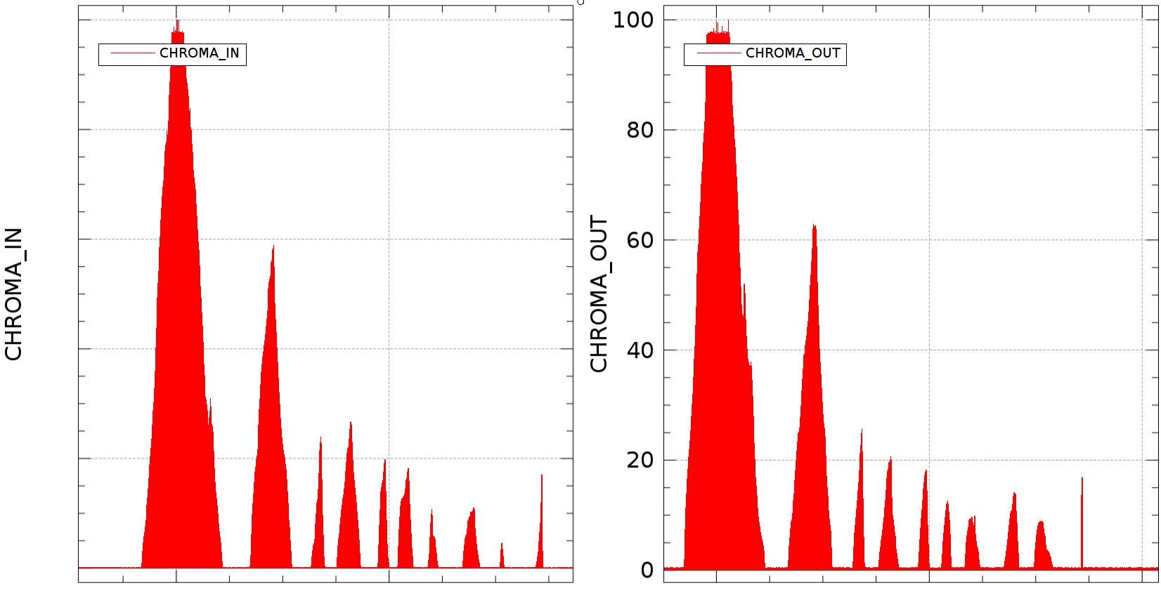
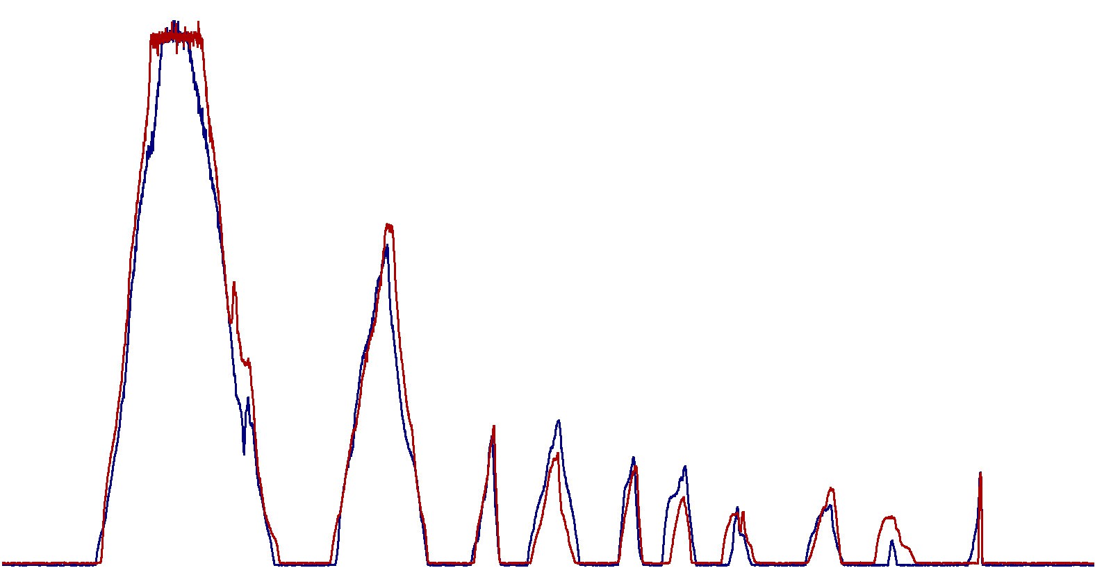
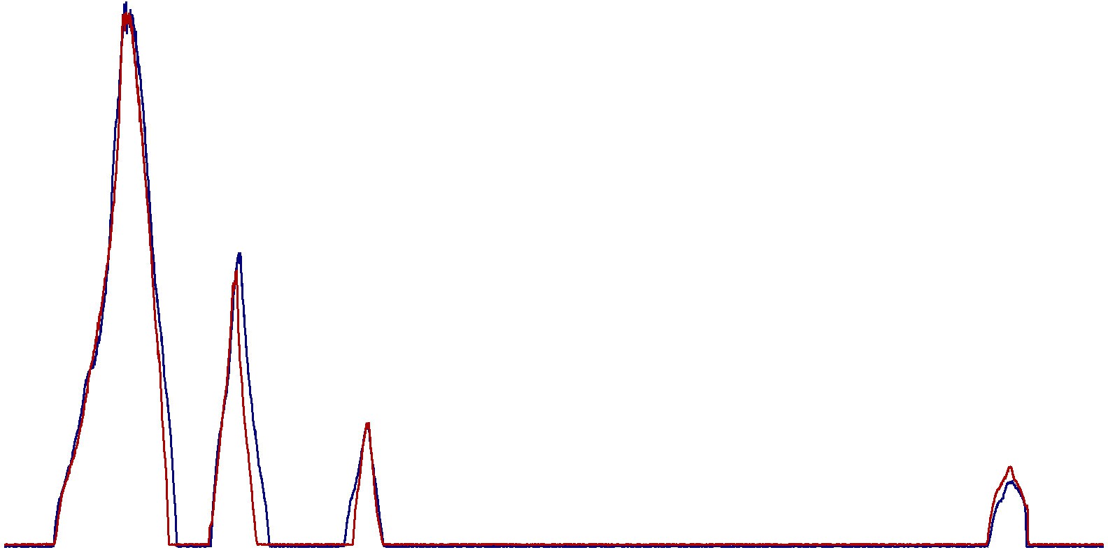
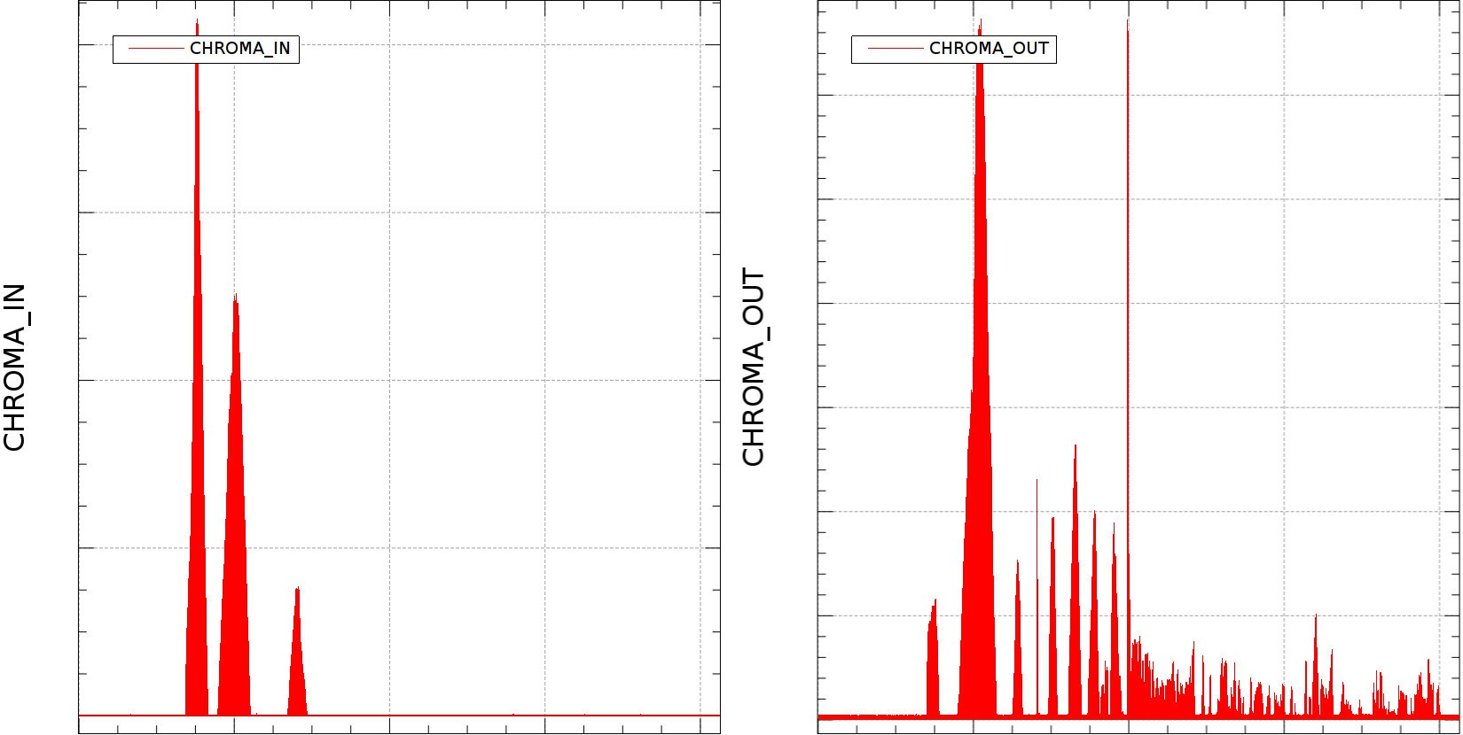
2.1. Normal air measurement
From left to right
First spike is atmospheric AIR: oxygen, nitrogen;
Second spike is the humidity in the air (water steam)
Third spike is Carbon Dioxide
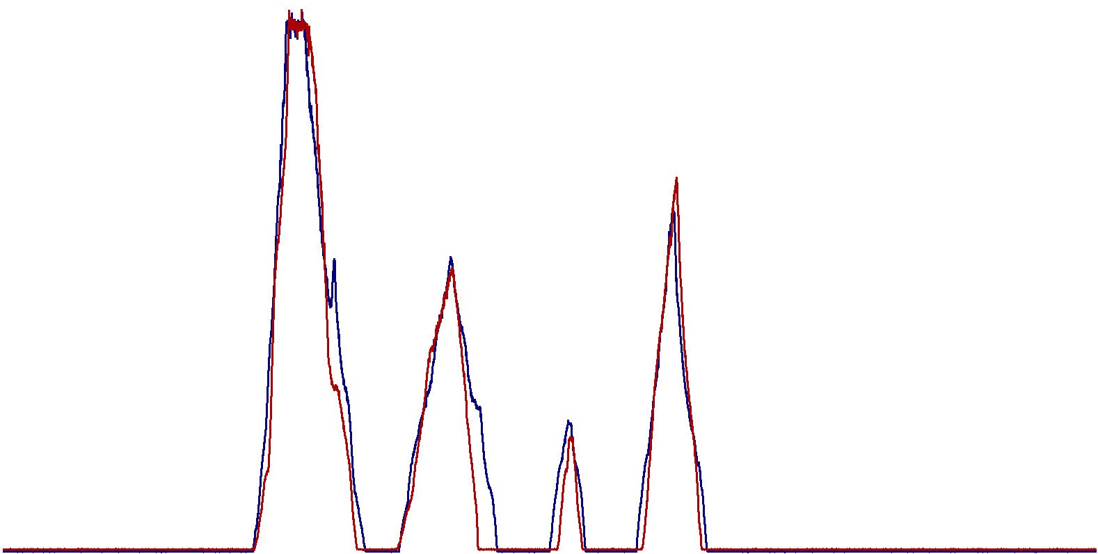
And these Chromas are weird. Their data do not really match.
First graph just came out, I think I found a little genius living just next door....

Blue color is Chroma In
Red color is Chroma Out.
And there are some differences between them.
.
.
2.2. Normal air and CH4 from some calibration gas tank I found in the warehouse:
- Atmospheric Air;
- Humidity;
- Carbon Dioxide;
- CH4 (last spike).
Second graph just came out:
.
.
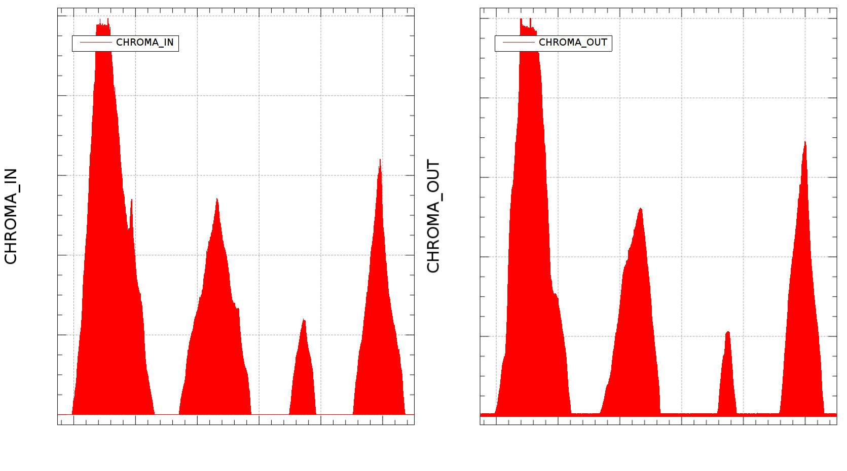
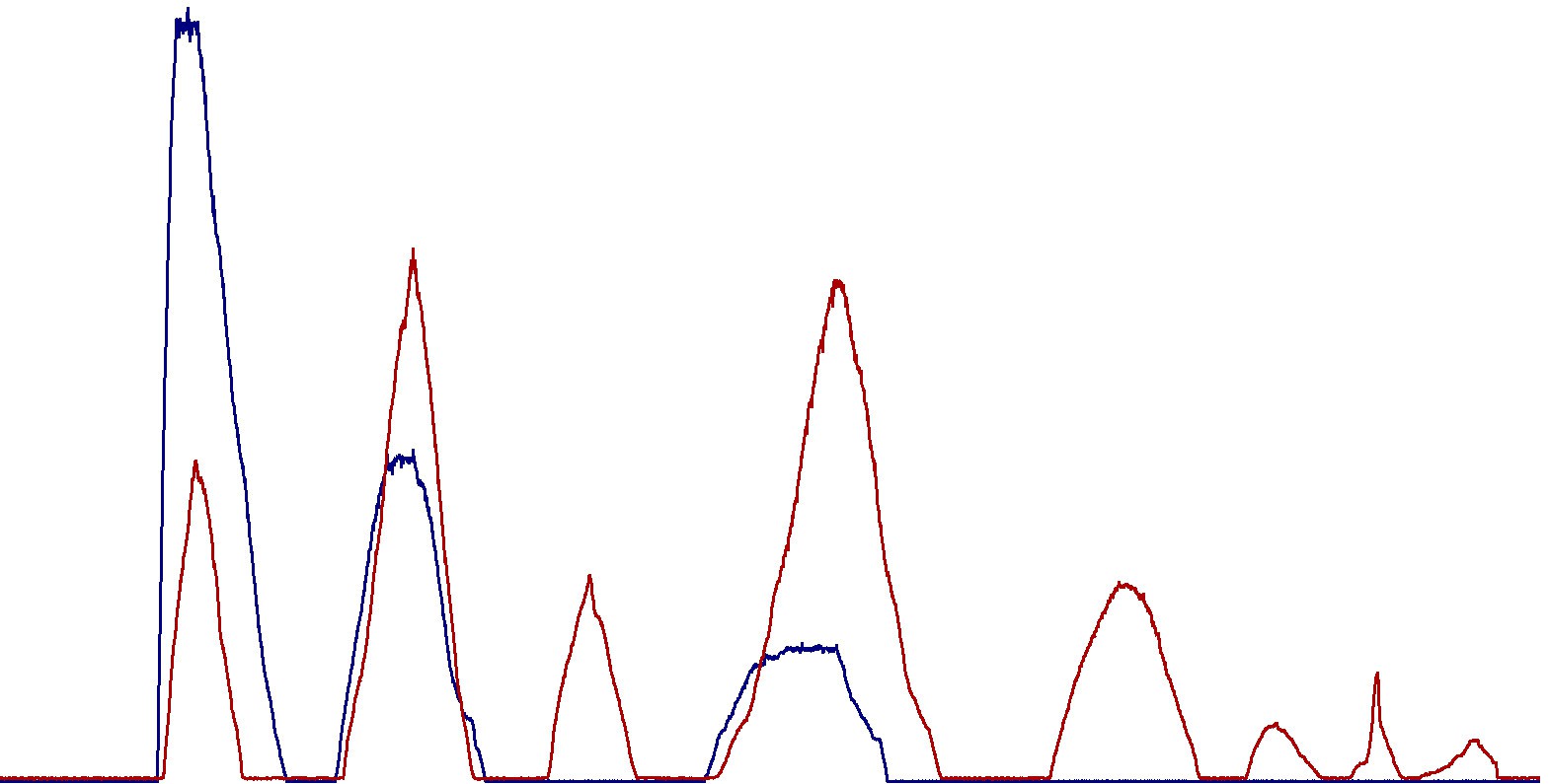
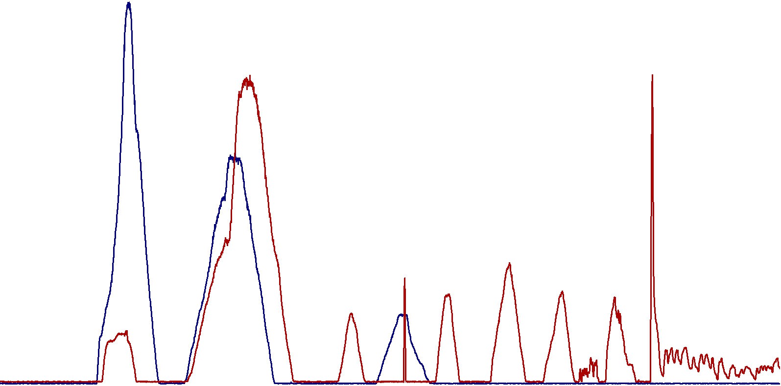
2.3. Normal Air + High End Calibration Gas
High End Gas contains a lot of hydrocarbons, CO2 and Nitrogen.
From left to right
- Atmospheric Air;
- Humidity (more humidity in Chroma Out);
- CH4 (C1 Gas. The number means how many carbon atoms are in the molecule)
- CO2;
- C3;
- iC4;
- nC4;
- iC5 (iso-pentane);
- nC5 (n-pentane);
- C2 (ethane);
And second graph is out:
.
.
2.4. Normal Air + Hydrogen Sulphide (H2S)

Last spike comes out after around 35....40 seconds. That's H2S.
.
.
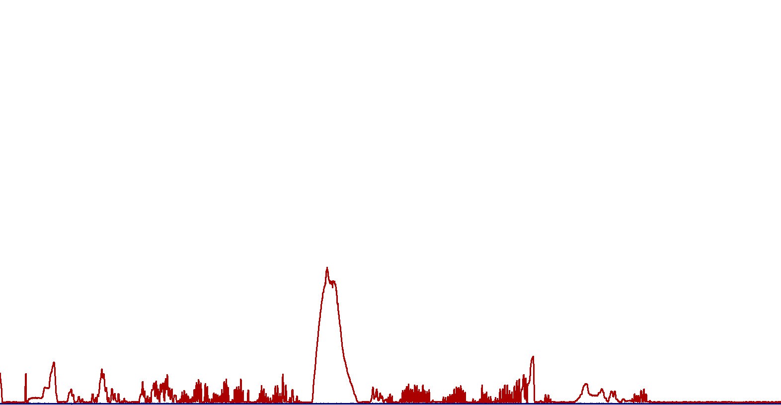
2.5. Engine Intake Manifold vs. Exhaust in normal conditions (no hydrogen)
We already know what Chroma In shows.
Now - Chroma out, interpretation from left to right:
----> ambient air components:
- 1st spike: Atmospheric Air (lower, that's because the car does not output ALL the exhaust in the Chroma. It also sucks air through the pump.
- 2nd spike: Humidity. A lot of it. Since the Gasoline respects European Union standards, I hope they did not add water in it. Looks like I'm either a victim of counterfeit fuel, or egine's cylinder head gasket is broken and engine coolant is leaking inside the cylinders;
------> hydrocarbons area:
- 3rd spike: Something close to CH4;
- 4th: CO2 is sky high, and I think Carbon Monoxide is also present in the same spike;
- 5th: something close to C3;
- 6th: more hydrocarbons in the area occupied by iC4;
There are some other spikes in hydrocarbons area, and among the last spikes there's something big which came out around the time corresponding to H2S.Detailed combined graph is out:
Zoomed: Air, humidity, CH4?, CO2(+CO?), C3?, iC4?
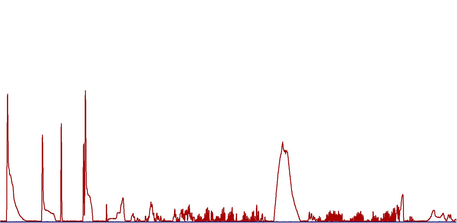
Last big spike - H2S
Again, H2S shifted left to see the rest.
.
.
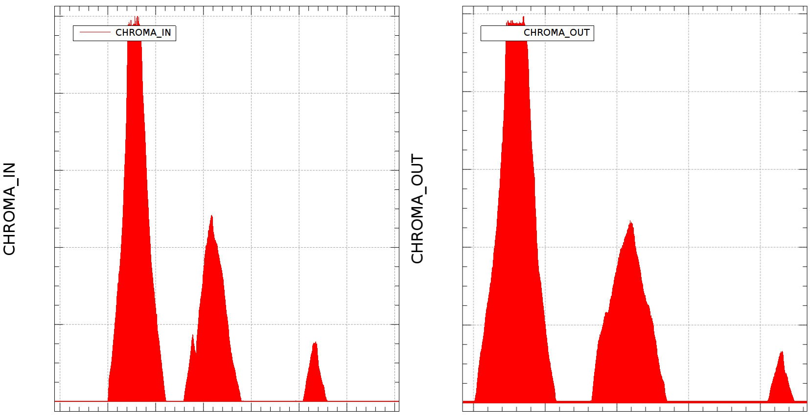
2.6. Engine Intake Manifold vs. Exhaust with added Hydrogen-Oxygen mixture
Things become interesting here, let's check it out:
Chroma In stays the same. It does not record the extra hydrogen+oxygen intake. It does not influence the Helium carrier gas, so it seems it keeps the TCD sensor filament at constant temperature. Humidity is a little higher than the previous Chroma In measurement, meaning there is some water steam coming out of the reactors;
Instead, Chroma out shows some weird results:
-1st spike (air) gets lower;
-2nd spike (humidity) goes sky high;
- 3rd spike (CH4) is lower than the previous measurement (without hydrogen-oxygen);
- 4th spike (CO2) - it comes as a small burst;
-----> hydrocarbons area:
- components are smaller in amplitude, there's a small burst of something I am unable to identify due to the lack of professional equipment;
Combined graph is out:
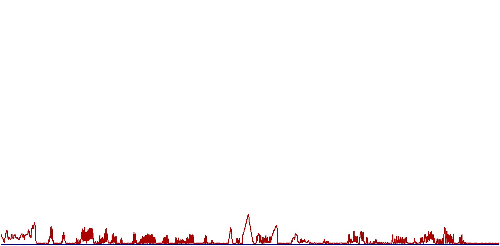
The bigger spikes came out starting with t=30s and finishing at t=45 seconds. Is H2S hiding in there? Graph is zoomed.
.
.
3. Conclusions:
According to this ancient tech I managed to rebuilt, and with the help of the theory explained in Science time (II) Reducing exhaust pollution article, I would really really really like to confirm the following conclusions using some professional, latest technology equipment and fresh calibration gases:
- The engine outputs some huge levels of pollution gases;
- Both Chromatographs were calibrated with gases and mixtures used in Petroleum Drilling process, more specific for Mud Logging Cabins Total Gas Detector and Chromatograph;
- Adding Hydrogen (+oxygen) mixture in the air intake manifold of ignition-based engines leads to reduction of Carbon Dioxide;
- I am unable to see any Carbon Monoxide spike, so I assume this gas is recorded in the same spike as Carbon Dioxide;
- Chroma Out graph is ugly during normal automobile engine operation, and it gets "cleaner" in the last case - when using hydrogen-oxygen mixture addition in the air intake manifold;
If this data is CONFIRMED by a THIRD PARTY to be valid, then this method can be successfully used to reduce pollution in big big cities - as a transition from traditional automobiles to hybrid, then fully clean means of transport.
This means cleaner streets, cleaner air, more trees, less cancer caused by smog, less problems in child birth - autism, cancers, malformations, low IQ, all the problem that Medical Doctors PhDs know and explain better than a System Engineering PhD, and people in important positions ALWAYS chose to IGNORE for whatever reasons.
[END OF TRANSMISSION]
______________________________________
kernel panic: improbability coefficient below zero
Discussions
Become a Hackaday.io Member
Create an account to leave a comment. Already have an account? Log In.
"2nd spike: Humidity. A lot of it. Since the Gasoline respects European Union standards, I hope they did not add water in it."
More than you'd expect from burning hydrocarbons? CxHy + (x+y/4) O2 -> (x) CO2 + (y/2) H2O
Are you sure? yes | no
I know there's water coming out. I was expecting it, but I'm not sure about the monster precision. My chemistry background is not so strong, so thank you for enlightening with the scientific explain. Thanks.
Are you sure? yes | no
My chem background isn't extensive either; just "high school" chemistry. But I think we can go a little further.
For alkanes y equals 2+2x in CxHy, so for the complete combustion of longer alkanes, the ratio of CO2 and H2O molecules will be nearly 1 : 1.
If I understand correctly, the area of a peak in the chromatogram is representative for the number of molecules of that type of molecule in the sample. The CO2 peak in the "no hydrogen" result is nearly as high as the humidity peak and a little wider at the base, so probably has a slightly bigger area than the humidity peak.
Gasoline has more complex stuff than just plain alkanes which would change the exact CO2 : H2O ratio one could expect from complete combustion, but based on the above I don't think the humidity peak is disproportional to the CO2 peak in the "no hydrogen" result.
Are you sure? yes | no
There's also humidity in the device, sometimes gases exit slower, sometimes faster. Metal pipes inside are corroded. That measuring device needs serious maintenance. I left it for 24 hours in a container in the sun to stay at high temperature and remove the humidity. This is why I wish for a 3rd party confirmation regarding results using some normal measuring devices. Look at the calibration graphs, they do not exactly match (chroma in and chroma out).
Also that engine leaks fluids everywhere.... cylinder gasket is compromised.
Thank you for following. I wish the HaD staff to show the same interest as you do, but this seems to happen only in my dreams.
Later edit: Last sentence confirmed at round end.
Are you sure? yes | no