Power Section:
I was working on TV this weekend to iron out the remaining issues. The cheap ebay LM2596 DC-DC switching converters arrived and would not work out of the box! Output voltage seemed fixed at 11.2V. I ended up spending quite sometime to debug the LM2596 board and after comparing the application circuit in datasheet found that programming resistor R1 was randomly selected to 330 ohms. R1 should by 1K 1%, Replaced R1 with correct value and was able to vary the output voltage. The precision pots on these boards were also no-name low quality ones, so ended up replacing them as well. Also, these boards have insanely bright blue LED at the output, I disconnected them. Cheap DC-DC converter modules were not cheap after all!
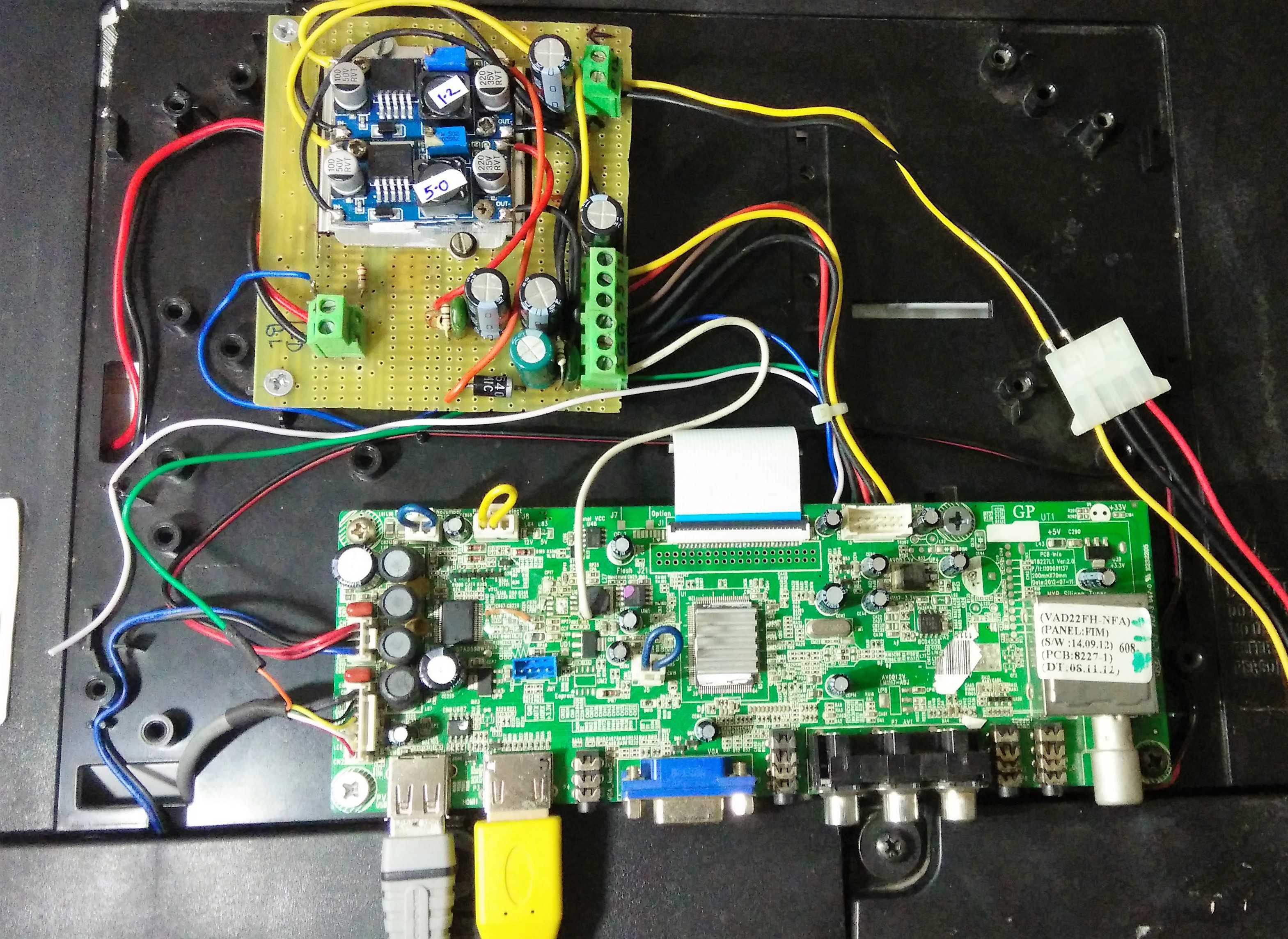
TV logic PCB needs 5V and 12V to operate. I decided to use a 12V,4A power supply and since Vcore 1.2V regulator was also fried, needed two of these LM2596 modules to step down (12 V to 5V) and (12V to 1.2V). The LED back-light also needs 12V which can be tapped directly off the input supply.
Switching regulators were mounted on a heat sink and I soldered everything together on a general purpose PCB. Added screw terminals for input and output voltages, LED backlight, added capacitors at input and output and also added a MOSFET to control LED backlight. Powered up and things were working ok. Output voltage seems stable and heatsink gets a little warm after some usage. I was also able to power the Raspberry- pi directly off the USB port of TV, this means less clutter and one less power adapter.

Fixing the Audio:
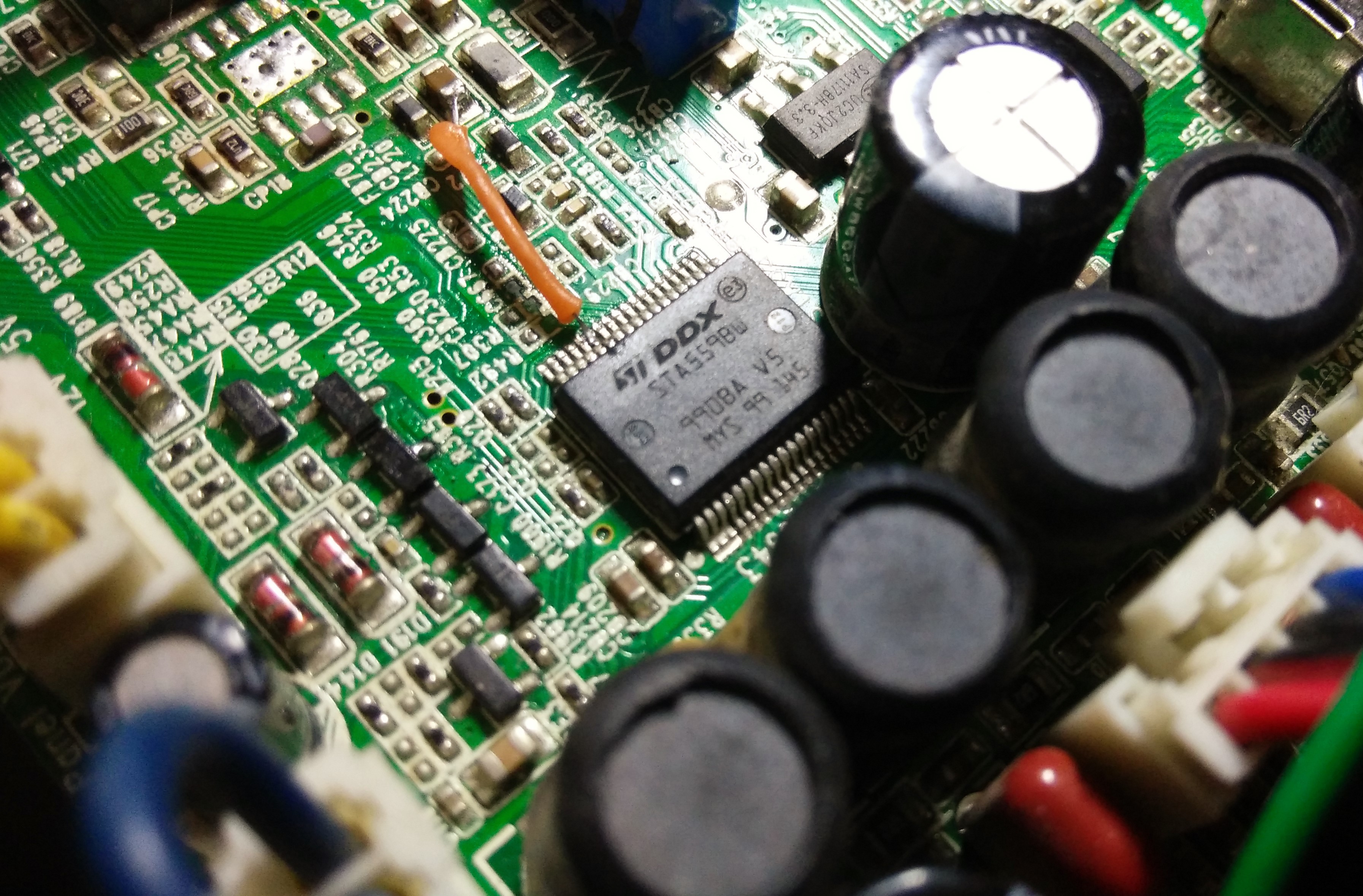
Audio is handled by ST micro STA559BW. This is a dedicated digital sound processor and has stereo Class D power amp integrated. The STA559BW datasheet is very detailed and in-depth and I don't think I will understand in a short time how this chip is implemented for this application. For now, I concentrated on checking the supply voltage, bias voltages, signal levels at various pins.
The power supply on all pins seems good and measure up to their respective voltage. I checked various digital signals using an oscilloscope and all signals were present - I2C SDA and SCL were good and SPI data input to the chip also seems active. Chip Enable was high, which was good. Chip RESET was held at -- Umm ... at 0.4V!!!
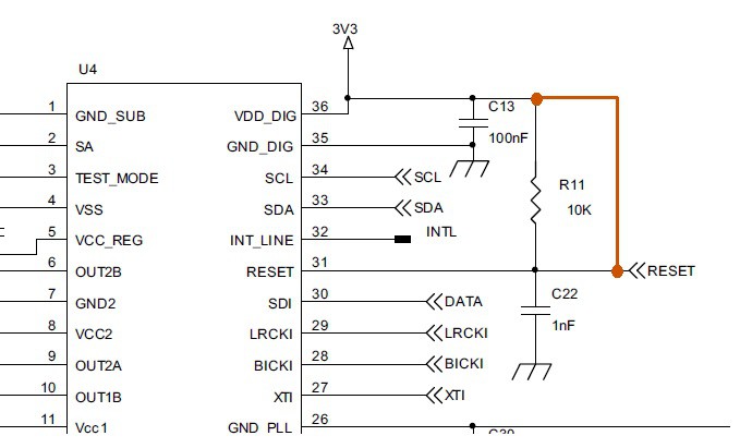
Datasheet says it should be at digital Vdd of 3.3 V. RESET pin is tied to 3.3V with a 10K resistor and 0.1uF capacitor to ground, which delays the reset rise at power ON.
There were no other components tied to reset pin - only a resistor and a capacitor and both of them tested good - so why the reset is held low at 0.4V? I desoldered the resistor and capacitor and connected a wire to the reset and added discrete 10K resistor and a 0.1 capacitor on a breadboard and I still saw the reset is hovering around 0.3 - 0.4V! replaced 10K resistor with 1K and still no good. I directly tied the reset pin to 3.3V Vdd and recycled the power - and I GOT SOUND --- YAAY!!


I still do not understand what may be the issue, my best guess is this chip is partially damaged and still works if reset is tied to Vdd. So my final fix was to solder a thin wire permanently between Vdd and Reset. works everytime and all the audio functions - Vol up/down, presets and equalizer works flawless.
This repair is complete and I am glad, I was able to get this working and a free TV for my Guest room :).
Thanks for reading.
 sidsingh
Discussions
Become a Hackaday.io Member
Create an account to leave a comment. Already have an account? Log In.