 Yann Guidon / YGDES
The signal generated by the crystal oscillators are, to say the least, weak and any influence (real or reactive) downstream will affect the resonator upstream. So the project has been blocked for years, among others, by the requirement of a very high input impedance amplifier. I have looked at differential amplifiers but it's pretty complex. If possible, it should be simple, right ? Well I have found one solution !
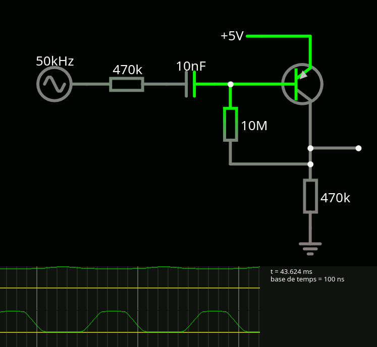
Two high-value resistors, one cap and one transistor, can you do better ? Here is the sim !
It is pretty neat and I simulated the high impendance with the 470K series resistor, just to prove the point. The series capacitor also helps separate the levels but there are many things to consider though.
First : it takes "a while" to start up when fed with an appropriate signal. In the sim, it takes about 30ms to stabilise. This is because it uses a silly trick : the series capacitor must also "charge" to the right level and it takes a while, through the 470K ground resistor. But once is starts to conduct, the 10M feedback resistor keeps the average base level at approximately the conduction level. The duty cycle is controlled by the value of the grounded resistor, 470K seemed to work BUT this resistor also affects the input impedance !
Second : I used a "near perfect" Silicon PNP model. Germanium will leak and spit noise, they drift with temperature, the bandwidth is not great... So the values might change and equilibrium is not certain, but the rough order of magnitude is here.
Anyway the circuit
- is pretty sensitive (I used a 1V input amplitude but it can be lower)
- sips very little current, since the 470K passes 11µA max (10× less than leakage)
- uses few parts
- is easy to tune (the ground resistor might be adjustable and that's it)
- amplifies greatly even when I limit hFE to 20
- saturates nicely...
Further amplification stages are required, the lower the hFE the more stages.
And now I realise it is very similar to one part of the circuit in log Crystal Oscillator (Germanium Edition). Except that this branch will drive a high-gain amplifier (then a current buffer), not a resonator.
We'll see how it translates in practice.
Discussions
Become a Hackaday.io Member
Create an account to leave a comment. Already have an account? Log In.
Because the two ends of the 10M bias resistor are in antiphase, the effective impedance to ground is 10M divided by the gain. So that will form an AC voltage divider with the input resistor of 470k.
Are you sure? yes | no
yeah something like that... But the sim shows a crazy amplification, even if I set the hFE to only 20. So I won't have to bin the transistors, hopefully.
I'll have to test it :-D But I must postpone this 2 weeks at least because priorities have been shuffled :-/
Are you sure? yes | no
I wonder how I managed to design circuits before simulators or personal computers. 😉 In those days I had heard of SPICE but that was something you had to create a job on punch cards for the mainframe and get waveform printouts on line printers. 🤷
Are you sure? yes | no
@Ken Yap yes, I have memories of my teens, where all I could access was mainstream magazines and some basic books at the library... I didn't manage much in fact. I hope it's not too late to catch up ;-)
Are you sure? yes | no