 Yann Guidon / YGDES
The OC70 is a "lazy" transistor and the 8KHz oscillator is close to its maximum working frequency. Yet this frequency must be divided because the digital counters need "time" to work. I've been naturally thinking of an analog circuit that oscillates at 1/2 or 1/3 of the input frequency, and gets synchronised to the input frequency, which would be the reverse of an "overtone" frequency multiplier.
Well this idea has been studied for a century already, as mentioned in http://www.leapsecond.com/pages/marrison/
"
This procedure was reversed by Hull and Clapp72, who discovered that the fundamental frequency could be controlled by coupling the high-frequency source directly into the circuit of the multivibrator. This, in fact, is a general property of any oscillator in which the operating cycle involves a non-linear current-voltage characteristic, being most pronounced in those of the relaxation type. Van der Pol and Van der Mark in 1927 reported on some experiments on "frequency demultiplication" using gas tube relaxation oscillators73. The multivibrator is, in effect, a relatively stable relaxation oscillator74, and with slight modification has been used extensively as the frequency-reducing element in quartz-controlled time and frequency standards throughout the world.
One serious difficulty with the multivibrator type of submultiple generator has been that, if the input fails or falls below a critical level, it will continue to deliver an output which, of course, will not hen have the expected frequency. Certain variables in the circuit, such as tube aging, may cause a similar result. With this in view, a general method for frequency conversion has been developed by R. L. Miller75, in which the existence of an output depends directly on the presence of the control input. The basic, idea involved in this, now known as regenerative modulation, was anticipated by J. W. Horton in 191976 but had not been developed prior to Miller's investigations. The circuit of a regenerative modulator in its simplest form as a frequency divider of ratio "two" is shown in Fig. 12.
Fig.
12--Frequency divider for ratio TWO employing regenerative
modulation.
"
So once again, reinventing the clock with old parts lets me discover century-old methods. I have seen a few relaxation oscillators used as frequency dividers and they look more practical than flip-flops, can run faster and use less parts.
It is possible to do a relaxation oscillator by combining a PNP and NPN transistor to create a SCR such as the "SUS" 2N4989:
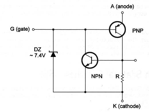
So it was a very fortunate idea that I got some OC139 (NPN Ge) !
For the Zener, a LED will also work, I suppose ;-)
The other benefit of a relaxation oscillator is the possible cross-coupling with the Xtal oscillator to "help" or "kick" it into oscillation.
My initial idea was more using an astable multivibrator. In fact that's what Injection-Locked Frequency Dividers (ILFD, discovered at Crystal oscillator with MOSFETs (new episode)) do, by modulating the operating voltage of the multivibrator with another transistor. The advantage of a multivibrator is that it uses only one kind of transistors so it will not use my short supply of 0C139.
Discussions
Become a Hackaday.io Member
Create an account to leave a comment. Already have an account? Log In.