 Yann Guidon / YGDES
I was hanging out on a Facebook group dedicated to Minimalist computing (which is perfectly in line with the #YGREC8 project) and a retired engineer dropped a little schematic.
Joseph Watson posted a circuit I have seen again and again, and consistently failed to make work : the venerable symmetrical bistable.
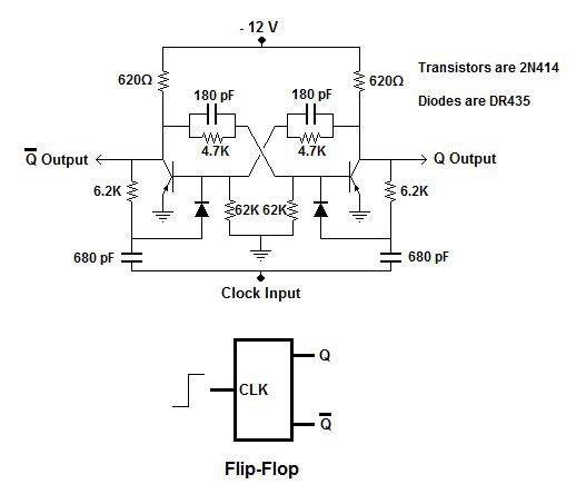
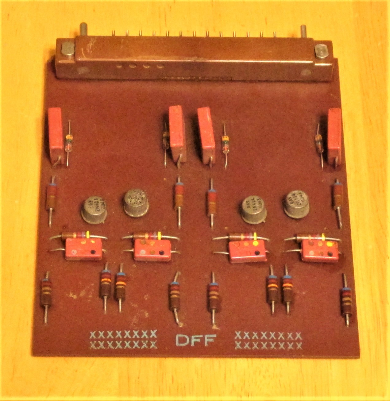
But this time with parts values !!! And this is a working circuit, as proved by his pictures of the circuit boards for his homemade computer built in the 60s.
This circuit can be easily reconfigured from divider-by-two to shift register :
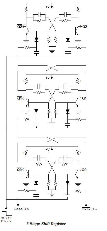
As we already know, this 3-stage Shift Register can be easily looped back on itself with one inversion (swap the positive and negative signals at one point) to make a 6-step Johnson counter. Which is exactly what a digital clock needs (for the decimal digit, and the unit digit needs 5 bistables) !!!
So what are the issues ?
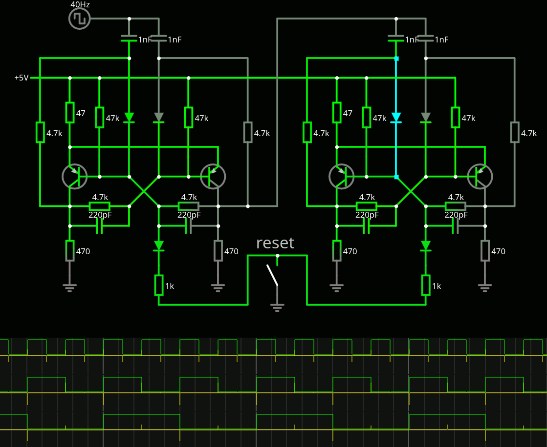
- First, I've always had troubles simulating this circuit with CircuitJS. Well, I made my own version of the above circuit (which does not differ from many other versions I have seen before) and this one works (when you get the diodes in the right polarity!).
I rounded the parts values to E3 and it passes the simulator, however it must be "bootstrapped" because it insists on initialising in a "stuck" state. That will be the job of a master reset ciruit.
- Second : Germanium drifts to Vbe=0.2 or 0.1 when the temperature rises. Which makes this type of grounded-emitter circuit difficult to operate. The parallel capacitors on the bases might help solve this issue but I have considered adding a diode on the ground side to "shift" the level. The VceSat might not bring the base down to the desired value to stick the circuit to the new desired state. Maybe a degenerating resistor and/or a diffpair-like topology could help too.
- Third : Speed. The RC constants might in fact slow the whole circuit down, but there is no choice because it's the only minimal circuit with identical transistor polarities. To get to 100KHz, a careful design is required : trying and choosing the appropriate resistors and capacitors... Not too large, not too small..
- Signal voltage swings are not characterised (over Vcc and temperature) and this will be another challenge. Here again, the capacitors will help, but also impede the frequency...
So this circuit brings in quite a lot of "analog design" but we can start from the transistors themselves : the above 2N414 are not far from the OC70 : they both are alloy junctions.
Some specs of the 2N414 : 3MHz, 24pF, hFE>60, 15V, 200mA, 200mW
The OC70 is more modest and I'll tune all my circuits for 10mA Ic and 1mA Ib to be more consistent with other, speedier references (because I want to use AF240 later).
From these values, one can deduce several values, and I'll keep the Vcc at 5V (because). So to get about 10mA at 5V, that's a 470 ohms resistor for the collector.
The Ib is 1/10th of the Ic so the base resistors are 470*10=4K7. Awesome.
There is a pull-down resistor for the base, that
- keeps the base at a low value when OFF, though it might not be low enough and the 10× value might slow down the off-turning. This is where "shifting" the emitter could be useful, as it would provide the pull-off resistor some headroom to totally discharge the base.
- limits the voltage on the base : 5V is applied to the base through 470+4K7 (that's 5K overall) but the 47K prevents the voltage from exceeding about 0.5V (in continuous operation). At 0.5V, the transistor can be considered "fully on"...
I'll have to check degenerating resistors, either individual of common, to keep the circuit from saturating too much. Using 100K instead of 47K for the pull-off resistors would be OK with 0.5V of degeneration, which means 47 ohms... Aaaannnnnnd this makes the circuit unstable... It's solved with a common resistor though.
There is another problem that the simulator does not let me estimate : the effect of the leakage currents ! 100µA here, 200µA there, and the whole balance might be shattered...
Yet another problem is that the transistor model is a standard silicon type with Vbe=0.6V so the values that work might not be right for germanium.
One more problem ! The clock signal must have a large swing : at least 4V for 5Vcc, as the simulation destabilises otherwise.
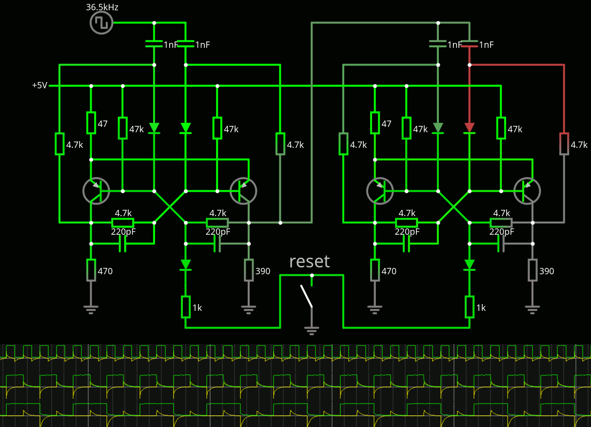
Anyway I have one version that seems to cascade decently :
...
I solved the init and another stability problem by reducing one of the resistors, from 470 to 390, this takes the circuit out of equilibrium and back to clear binary state. I seem to be able to simulate easily up to 36KHz with the above caps, I doubted that the 1nF could charge fast enough through the 4K7 feedback resistors...
Now this does not account for 1) lazy transistors 2) leakages 3) Vbe.
But at least I could validate a clock buffer using an emitter follower.
Discussions
Become a Hackaday.io Member
Create an account to leave a comment. Already have an account? Log In.
So you got the circuit to flip without flop? 👍😜
Are you sure? yes | no
That is what happens when you lose one sandal.
Are you sure? yes | no
Did you try my circuit that worked in 2016? ;)
https://hackaday.io/project/10698-clockwork-germanium/log/35585-triggering-germanium
Are you sure? yes | no
Looking back at it, I'm still .... confused :-/
I need to simulate it, now that we have CircuitJS :-D
Are you sure? yes | no
You probably need full-scale SPICE to simulate it properly :)
Are you sure? yes | no
@SHAOS or simply try it for real
Are you sure? yes | no