 johnowhitaker
Here's a summary of the project so far, to save you judges (and anyone else interested) from having to dig through all the old logs just to get an idea of what this project is about. Here goes:
The goal was to make a small laser engraver, and figure out a way to use it for making PCBs. After trying to cut away tape, or use a permanent marker to outline traces, we came up with a rather novel way of doing it.
A 'toner paint' is made by mixing toner powder from a laser printer with alcohol. A copper clad board is coated with a layer of this toner slurry. A laser attached to the XY system is used to selectively melt the toner in the desired pattern. The un-melted toner is removed, leaving a nice etch resist.
I burnt out my laser(s) messing around, and deleted some photos of the latest progress (!!). Nonetheless, the basic idea is sound, and the technique does work. However, I am interested to see how far it can go. The next logical step is to use melted toner as a silkscreen as well, but beyond that I'd like to try a technique similar to the light-scribe method for making capacitors. Except that by adding alternating layers of toner (as dielectric) and graphene we could potentially get caps with more surface area (and thus greater capacity). All that will have to wait until I can scavenge a new laser or buy one with the seed money :)
For those wanting step by step instructions, a good set to follow are those by groover on instructables - http://www.instructables.com/id/Pocket-laser-engraver/. His design is very similar to the one I ended up with. Or, search for microslice as they too have a good breakdown of the software and hardware parts of a build like this.
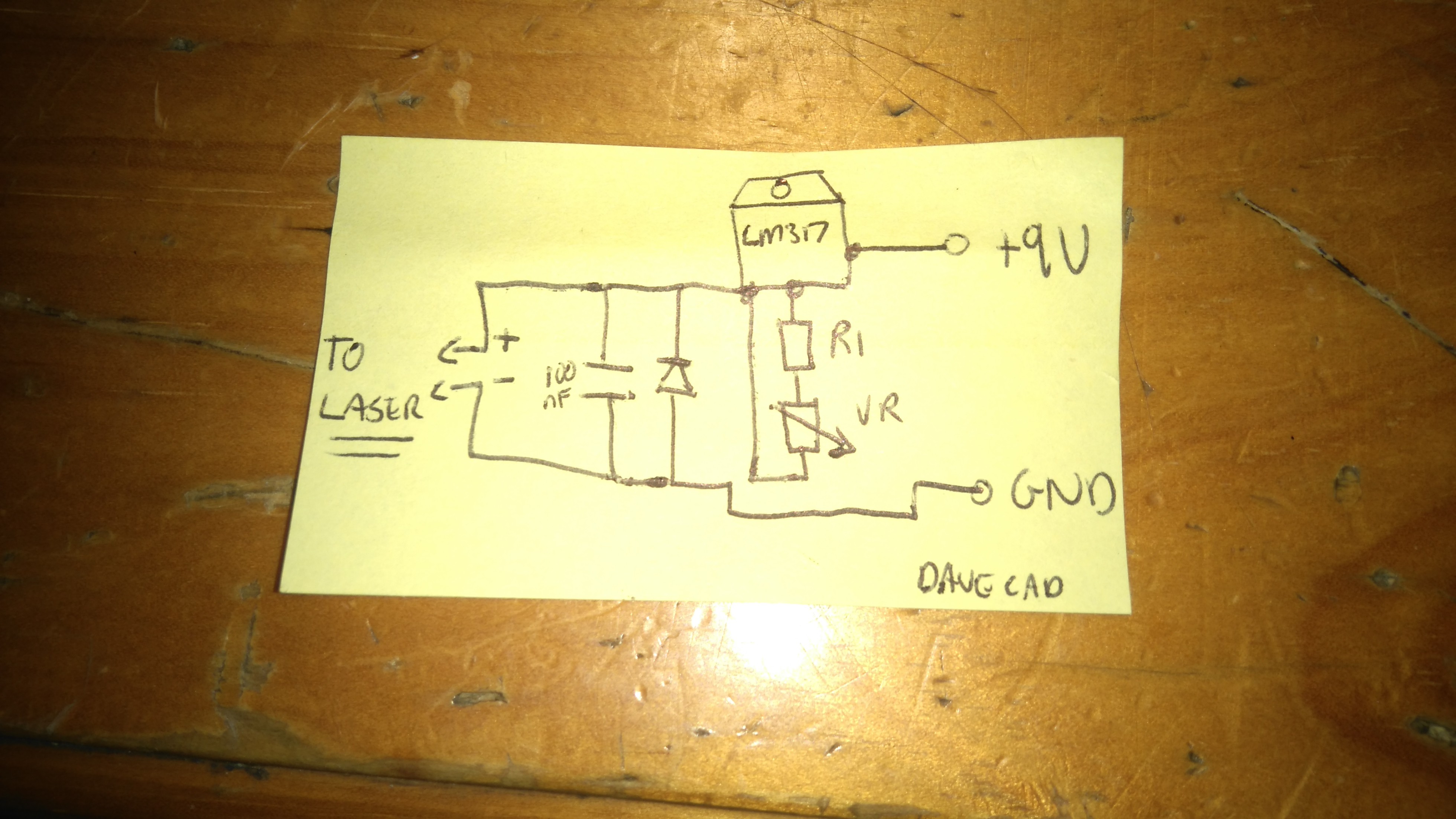
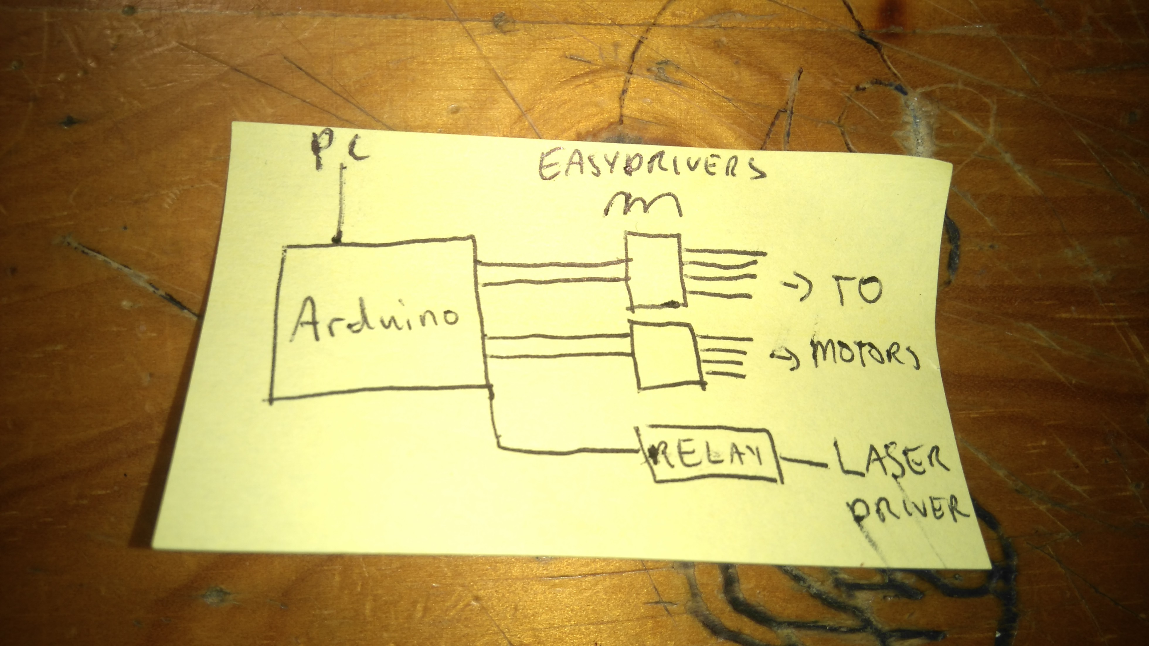
The laser driver I use follows the instructions at http://www.langeder.org/homemade-laser-driver-with-lm317/, with a few modifications. I did at one stage use a mosfet to switch the laser, on and off but switched to a relay for the latest build because it was easier, plus the click and glowing light on the relay module are useful for debugging. I also modified the inkscape extension from the microslice guys, so that it now uses M4 to turn the laser on and M3 to turn it off. Those commands toggle an LED on pin 13 in the default GBRL setup, and it is trivial to wire up pin 13 to the relay module as well.
Also, between the 9V supply and the laser driver is the relay module, so that it only has power when the arduino writes pin 13 HIGH. Here's a block diagram:
 I really think this technique has promise, and I hope I can take it further over the course of this contest.
One final note: I (Jonathan Whitaker) focused on my system in this log, but my team-mate @esot.eric is replicating this system as well. He has been able to melt some toner manually, and I look forward to his results once he gets his XY system going. His #CD/DVD mechanisms and cartesian thinggie[s?] project and comments on my old #Mini Laser Cutter persuaded me to dig out my old project and try this. That's the power of a community like hackaday.io :)
Discussions
Become a Hackaday.io Member
Create an account to leave a comment. Already have an account? Log In.
Hope you don't mind my sharing: I've been keeping a couple tabs open (starting up every time I open my browser) with photos from your experiments as motivation:
Impressive work accomplished in a dorm-room with a handful of tools and essentially trash!
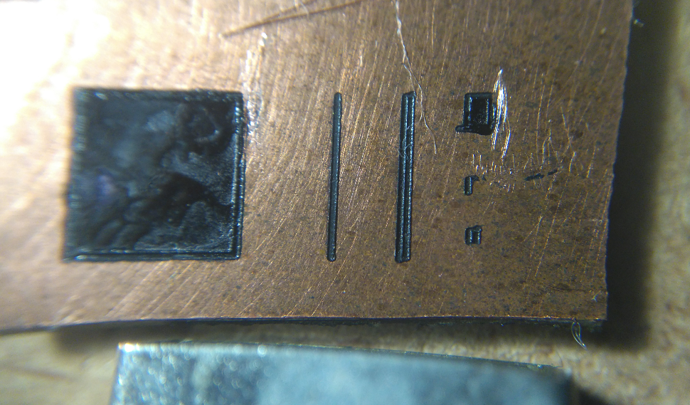
(For the uninitiated: Don't let the "artisanal-quality" of the PCB-artwork fool you, that was an early proof-of-concept experiment with a *hand-switched* laser, prior to the addition of the automated laser-switching. And, further, the two images aren't even from the same experiment. MORE IMPORTANTLY: Look at that LED for scale, we're talking trace-widths and spaces easily small enough for TQFPs accomplished with little more than "one man's trash," some open-source hardware/software, and "another man's" inventitiveness).
Excellent Motivation, and "Shows Promise" is an understatement.
Are you sure? yes | no