 Vijay
VijayThe micro stepper motors I ordered just arrived, and god are they brilliant!
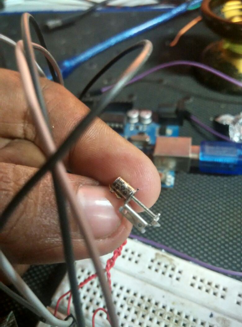
I did some rudimentary experiments about the amount of torque it has, and if it would suffice for my application, and I think it would, although i'm afraid it might miss steps.
I'm driving this straight out from the Arduino pins that should be ~40mA source and sink. Possibly some more juice from a proper driver will do the torque some good.
Let me know what you think. I would also like to thank all those who responded to my earlier log, especially @HTCPCP 418, whose micro stepper motor driver approach, ill probably be taking.
Ill be uploading CAD data for these motors in a few days if anyone is interested.
The link to this motor is : http://www.aliexpress.com/item/50pcs-2-Phase-4-Wire-Micro-15-Step-Motor-Screw-Rod-Stepper-Stepping-Motor-Free-shipping/32222560547.html?spm=2114.13010608.0.78.tjruAc
Discussions
Become a Hackaday.io Member
Create an account to leave a comment. Already have an account? Log In.
Hi, I came across your great project because I also am looking for a way to control many of these very small stepper motors (between 15 and 20). I think I even have the exact same ones you bought. How are you managing? Specifically:
1. What driver electronics did you eventually settle on and try? I love HTCPCP 418's very detailed suggestions on cost effective ways to drive so many tiny motors. I was finding the costs and pins of using dedicated driver chips for each motor quickly adding up.
2. With regard to the motors themselves, how are you coupling to the motor's leadscrew? My motors came with a plastic sleeve that just slides up and down the leadscrew. I thought I would be able to remove the metal bracket and put an M1 nut on there, but the bracket is firmly attached to the motor, so I have to cut it off to put a nut on. In your demo video, it looks like you simply pushed some aluminum foil onto the lead screw and it's working...
3. What's the fastest you've been able to drive the motors? My loads are low but I'm looking to position as quickly as possible. Micro stepping isn't necessary.
4. Can you share the arduino code you used for testing the motors? I would like to perform the same test you did in your video.
Thanks very much. Sorry if you have this info elsewhere and I missed it. I am new to hackaday. I signed up just to post this comment, but it looks like a cool community!
Are you sure? yes | no
Vijay where did you order these stepper motors from and any good 3d printing services that you know of that I could use?
Are you sure? yes | no
I think the link at the end of the log answers your question ;)
Are you sure? yes | no
Hi @johnsamisoni, the link is in the log. I run a 3D printing company (www.fracktal.in) so 3D printing isnt a problem from me :p
Genta from exiii swares by shapeways for his high end prototyping, and uses FDM for inhouse prototyping.
Are you sure? yes | no
Would the 3D printing company be able to send to New Zealand
Are you sure? yes | no
Also, regarding the FPGA/CPLD idea I wrote about in the comments to your earlier log: CP2130 would be a lot better than PL2303, as SPI is actually a better fit for this application. You could both use it for programming the FPGA (so you don't even need a configuration memory) and for communication.
Communication could be implemented easily inside the FPGA (no need for any mcu or even softcore). Via SPI, you would have access to the registers. There would be a few registers for version info, connection test, etc. Then, you'd also have one register per cell. By filling those registers with 6-bit values (e.g. subtracting 0x2800 from the Unicode values https://en.wikipedia.org/wiki/Braille_Patterns), you would tell a certain cell to move to a new value. Burst writes could be used to set multiple cells at once.
A program on the computer would be used to first load the configuration into the FPGA and then sending the proper values to the display.
Another advantage of this: It would be really easy to connect with any embedded project as most mcus have some way of communicating via SPI.
Are you sure? yes | no
I thought a lot about your concept. One thought I had was: technically, it would be easier to get rid of the pogo pins by simply sliding an embossed strip of material around instead of one with holes. Of course, this would result in slightly recessed braille cells. Since I have no experience with braille: Do you know how much that would affect someone trying to read the braille?
If that would slow readers down too much, another possibility would be flipping the whole assembly around: Move embossed strips of material around and use pogo pins to bridge the gap. This way, the cells would not have to be recessed.
From my point of view, there are multiple benefits to this design over the current one:
1. You don't need a mechanism for moving all pins at once.
2. You don't have to check the position of the pins before moving the cells.
3. Cells could be updated individually while other cells are being read. This could be used for stuff like automatically updating the top cells while the reader is close to the end of the current "page". You could even "display" things like a clock or status bar that gets automatically updated.
4. Updating individual cells while the user is already able to read the content of other cells could allow lower power consumption with less of an impact on the user.
Are you sure? yes | no
HI, could you elaborate? i didnt get "Move embossed strips of material around and use pogo pins to bridge the gap"
I too have been considering other options other than moving the pogo pins up and down. Now that i have the pins, turns out their springs are quite strong, and if I bunch them up and depress them simultaneously, requires considerable amount of force.
The manufacturer in china is cool though, and says they will customize the springs to my requirements, so there is a plan B, while I screw with the pogos I have to reduce the force they exert.
I have considered using ball bearings, inside the holes of the top plate, covered by a flexible membrane so that they dont pop out, and the strip sliding underneath would be embossed. It would work like a linear cam, with the ball bearings the followers, held in position horizontally by the hole in the top plate.
One thing that's irritating to work with is that i have only about 6.5mm of lead on the lead screw motor to work with. I somehow found an arrangement that works with holes for the pogo's to go through, but I need to still figure out the embossing pattern if i'm going for ball-bearings.
I just got the BU24035GW, I thought I could deadBug solder one to test it out, but had a reality check after I opened the parcel.
I'm not to familiar with FPGA, and will look to that as a fallback.
Also, I should thankyou for all your help and support, its really motivating!
Are you sure? yes | no
A great example for what I am thinking of are those stamped battery contacts like the ones at the bottom in this picture: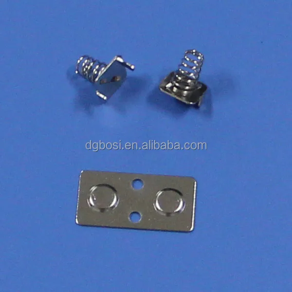
Instead of having holes in the strips that you move around, let a bit of material protrude from the strips. Then add some pogo pins over them so you can have a flat top.
I guess the best way to think of it would be the way a lock works.
Just imagine you cut of the top of the cylinder to the point where you can get rid of the springs (with pogo pins, they would be in the pin). That's where the user could feel the difference in height between the low and high spots on the strip you move around. Also, you obviously only have two heights.
Reading the rest of your reply, you were mostly thinking along the same lines. I don't think ball bearings would be necessary. However, the pins and strips have to be made of metal. Flipping the pins you showed a photo of in one of your earlier logs could be sufficient. That's the what I meant by the sentence you quoted.
Your membrane idea sounds pretty good. I guess, whatever material you try should be very smooth to not annoy the users.
If you got the right pattern for the holes, you should try turning them into a battery contact-style embossed strip. Also, you should be able to combine adjacent holes to simplify everything a bit.
Regarding the driver: Deadbugging those little critters can be done, you need thin wires, a good soldering iron and a lot of patience, though ;)
Regarding FPGAs: I guess it's an occupational hazard to start liking certain chips more than others. Especially in cases where multiple things have to be done simultaneously, I have come to prefer them over microprocessors. Especially with those really cheap Lattice chips.
Since I am currently working on a project where I also have to drive multiple motors at the same time - though a bit bigger than the ones you are using and not quite as many - I could probably send some of the Verilog code your way if you are interested. Most of the stepper driver stuff could just be copied multiple times, it would be even simpler in your case, as you don't need micro-stepping.
Are you sure? yes | no