 Tom Meehan
While I've been able to find quite a few online sources for instruction in 'C', I really wanted a decent reference book (a physical one made of actual paper) to use. I finally broke down and ordered a copy of “The C Programming Language” by Kernighan and Ritchie.
I've been able to find a solution to an issue that's been vexing me for awhile – sending the values in variables out to the LCD.
char s[12]={0}; //declares a char array with 12 positions and clears the array
sprintf(s,"The value of J =",var1 ); // saves formatted characters, including 'var1' to the array 's'
LCDString(s); //sends formatted array to print on the LCD
So far this is working fine and lets me combine text and values from variables and print the results to the LCD. This was tough for me to figure out because it is something that seems to be obvious to anyone who has learned 'C'. Most courses on 'C' seem to cover 'printf' and 'sprintf' fairly early. So, being pretty new to 'C' and not formally taught I missed it - well now I will not forget that little piece of knowledge.
I've posted my most recent changes to the full source code at Github Universal Glucometer.
I keep reviewing the datasheets again and again. As I understand more I end up having even more questions and have to delve deeper to find the answers – it is slowly becoming less intimidating.
Illustration of the
hardware/software implementation for strip reading.
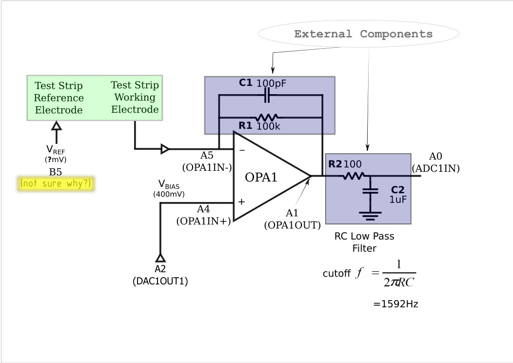
Below is the
Initialization code for the meter, the sets up the Fixed Voltage
Reference, DAC, ADC, OpAmp, etc. (it is in the user.c file of the
source code). This code shows the settings for the register pins in the illustration above.
void InitApp(void)
{
    /* FVR CONFIGURATION */
    //FVRCON = 0x88;
    FVRCONbits.FVREN = 1;
    FVRCONbits.CDAFVR = 0b10; //Comparator and DAC Fixed Voltage Reference Peripheral output is 2x (2.048V)
    FVRCONbits.ADFVR = 0b10;// ADC Fixed Voltage Reference Peripheral output is 2x (2.048V)
    // PORT A CONFIGURATION
    ANSELA = 0x3F;
    TRISA = 0x3F;
    ANSELAbits.ANSA3 = 0;
    TRISAbits.TRISA3 = 0;
    // PORT B CONFIGURATION
    TRISB = 0;            //PortB to output? then set individual bits?
    ANSELB = 0;           //Port B pins all set to digital++++
    TRISBbits.TRISB0 = 1; // PortB bit0 digital input STRIP_SENSE
    TRISBbits.TRISB5 = 1; // PortB bit5 digital input (REF_OUT Vref for strip)
    TEMP_SENSE_VDD = 0;
    TRISBbits.TRISB2 = 1; // PortB bit2 analog input TEMP_OUT
    ANSELBbits.ANSB2 = 1; // PortB bit2 analog input TEMP_OUT
    TRISBbits.TRISB3 = 1; // PortB bit3 digital input SW3
    TRISBbits.TRISB4 = 1; // PortB bit4 digital input SW1
    IOCBNbits.IOCBN4 = 1;
    IOCBFbits.IOCBF4 = 0;
    IOCBNbits.IOCBN3 = 1;
    IOCBFbits.IOCBF3 = 0;
    REF_OUT = 0;
    // PORT C CONFIGURATION
    TRISC = 0;
    //TRISCbits.TRISC7 = 1; //Rx is input
    // OPAMP CONFIGURATION
    OPA1CONbits.OPA1EN = 1;
    OPA1CONbits.OPA1SP = 0;
    OPA1CONbits.OPA1PCH0 = 0b1;// 0b10; // SELECT DAC AS INPUT TO  OPAIN+
    OPA1CONbits.OPA1PCH1 = 0b1;// 0b10; // SELECT DAC AS INPUT TO  OPAIN+
    // DAC CONFIGURATION
    DACCON0bits.DACEN = 1;
    DACCON0bits.DACOE1= 1;
    DACCON0bits.DACNSS = 0;
    DACCON0bits.DACPSS= 0b10;
    OPTION_REGbits.INTEDG = 0;
    OPTION_REGbits.PS = 0b111; // timer 0 prescale = 256
    // Enable interrupts
    INTCONbits.INTF = 0;
    INTCONbits.INTE = 1;
    INTCONbits.GIE = 1;
    INTCONbits.PEIE = 1;
    PIE1bits.ADIE=1;
    INTCONbits.IOCIF= 0;
    INTCONbits.IOCIE= 1;
    VREGCONbits.VREGPM= 1;
}
For additional information about the different modules (OpAmp, DAC, ADC, Comparator, FVR) I've listed the page numbers of the data sheet for the PIC16F1784 (includes -84, -85, -86 and -87) that each module begins on.
- OPAMP Module p185
- DAC Module (digital to analogue converter) p189
- ADC Module (analog to digital converter) p167
- Comparator Module p193
- Fixed Voltage Reference Module p160
I've been concerned about the bias voltage for different test strips and I was happy to find that it is possible to adjust the outputs from the DAC's through the software/firmware and adjust the bias voltage.
The other issue I'm working to resolve - the Vref supply to the strip. Currently this is assigned to RB5 (which is configured as a digital input). I believe the Vref should be a negative polarity (so configuring the pin as an input makes sense) but I do not see regulation of the potential (V-). So, to begin I'll need to read this pin to see what it's potential is with reference to GND and to 3.3V. I'll be checking this ASAP, since it could have direct implications on my board design.
Additional pieces of the design I've been working on:
- Adding NPN transistor to switch the back light of the LCD on, when switching on from sleep mode. (I choose an NPN bipolar transistor instead of a MOSFET because the older NPN's are pretty easy to source, or even pull off of old circuit boards).
- Power supply. My current plan is to use 3xAAA batteries with a low
dropout 3.3v regulator.
- While it would be nicer to use a lipo cell with a charger circuit I feel that AAA batteries are easier to acquire iand less expensive than a lipo cell and charger circuit.
- PCB Design
- I am working hard to re-configuring the reference design (along with my changes) to port it to the PIC16F1789 chip (it's about the same cost and has more IO pins and on board memory). I'm also adding an additional EEPROM chip to expand the memory for storing the settings for regression equations (slope and intercept values), settings for the reference and bias voltages, etc. Basically, the data needed to change settings for on the meter to read different brands (and lots) of strips. I want to leave room to be able to transfer the saved testing data to another source and upload additional data to read more strips.
- Hopefully I can finish the basics for this in the next day or 2 so I can order boards from OSHPark that include current functions and break out the pins needed for the additional functions I would like.
I'll be posting up the new schematics shortly, that includes the changes mentioned above.
Discussions
Become a Hackaday.io Member
Create an account to leave a comment. Already have an account? Log In.