 Ted Yapo
My relays aren't here yet, and I'm bummed out about it, so I decided to simulate one so I could design some of the more analog parts of the clock, like the power-on reset circuit.
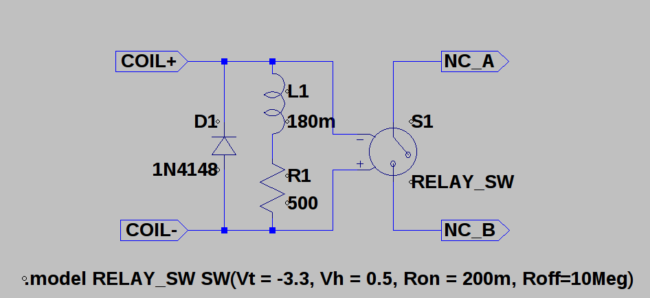
This is what I came up with. The coil resistance is specified by the manufacturer, as are the pull-in and drop-out voltages (modeled here as a threshold and hysteresis value). What they don't tell you is the coil inductance. I guessed at a value based on the pull-in and dropout times and the voltage thresholds. With a 180m inductor, the switch in this model has similar timing to the published relay specs.
To get a normally-closed output, I reversed the connections to the voltage-controlled switch component and used a negative threshold voltage. This whole circuit can be encapsulated in an LTspice symbol, shown here switching an LED:
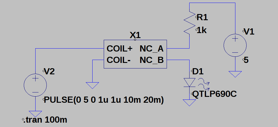
When the input is high, the switch is off, and vice versa:
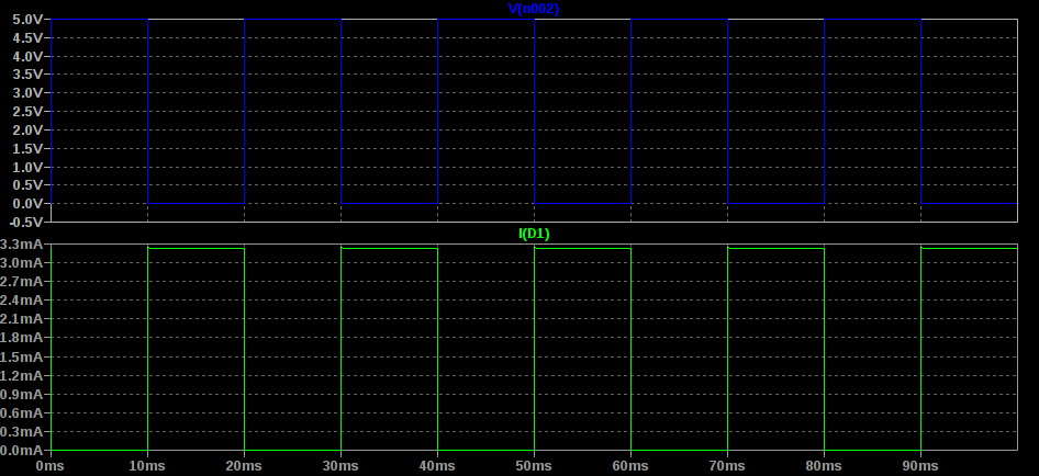
Which isn't really that impressive, I guess, but that's not really why I made the model.
Slightly more interesting is the power-on reset circuit:

The supply starts at 0V and comes up to 10V at 100ms. R2 charges C1 slowly, delaying the opening of the relay contacts. With these values, the delay is about 350ms:
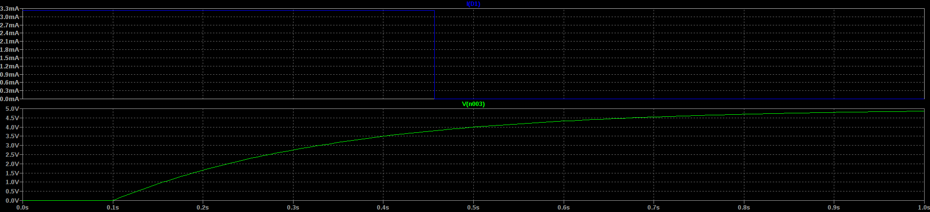
You can see the linear ramp (bottom; green) and the LED current (top; blue). The LED here represents the reset line for all the flip-flops. They'll be held in reset for those initial 350ms, ensuring they start in a known and stable state.
Is this a perfect simulation? Probably not - some values will need to be tweaked when I move to the real hardware, but I can get a qualitative feel for how things will work.
Oh, and here's another one, an RC relaxation oscillator:

It's the same thing you might see made with a Schmitt-trigger inverter, and relies on the hysteresis of the relay to switch on an off, charging and discharging the capacitor. Here's the output:
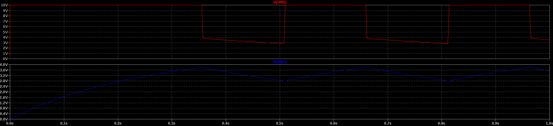
The bottom trace (blue) is the voltage on the capacitor charging and discharging, with the output shown in the top trace in red. It oscillates at about 3Hz with these component values. Is it stable enough to keep time? Absolutely not. Probably not, anyway.
Discussions
Become a Hackaday.io Member
Create an account to leave a comment. Already have an account? Log In.
I have played with actual relays with this kind of circuits and it gets tricky quickly.
For example, SPST is the worst choice :-D SPDT is already hard, I wish I could use DPDT as it would simplify a lot of things.
RC networks are tricky, like, try to avoid them. You end up with very small resistors and huge capacitors, and I have burned a relay with a relaxation oscillator.
Use a ring oscillator instead. More relays but better stability and you can change the frequency by changing the length of the loop.
Are you sure? yes | no
Yes, SPST is the worst, but that's what they were selling cheap, and I felt up for a challenge :-)
But, wait, SPST normally closed is the worst of the worst. I'd rather have SPST normally open. This is probably why I got them so cheap.
The relaxation osc is just for amusement. It wouldn't keep good time, anyway. I have a rubidium oscillator I can use for a timebase if I can find a simple GPS-disciplining setup (cheaply and easily).
But, the power-on reset timer should work fine. It doesn't have to be precise at all, and it's not like I expect to power cycle the thing very often.
Are you sure? yes | no
You must compare with real-life measurements.
For example bounces can be tricky...
Are you sure? yes | no
Yep, but the relays are still in the ail, and I want to work on this *now* :-)
I got the relay itch.
Are you sure? yes | no