 robert.c.baruch
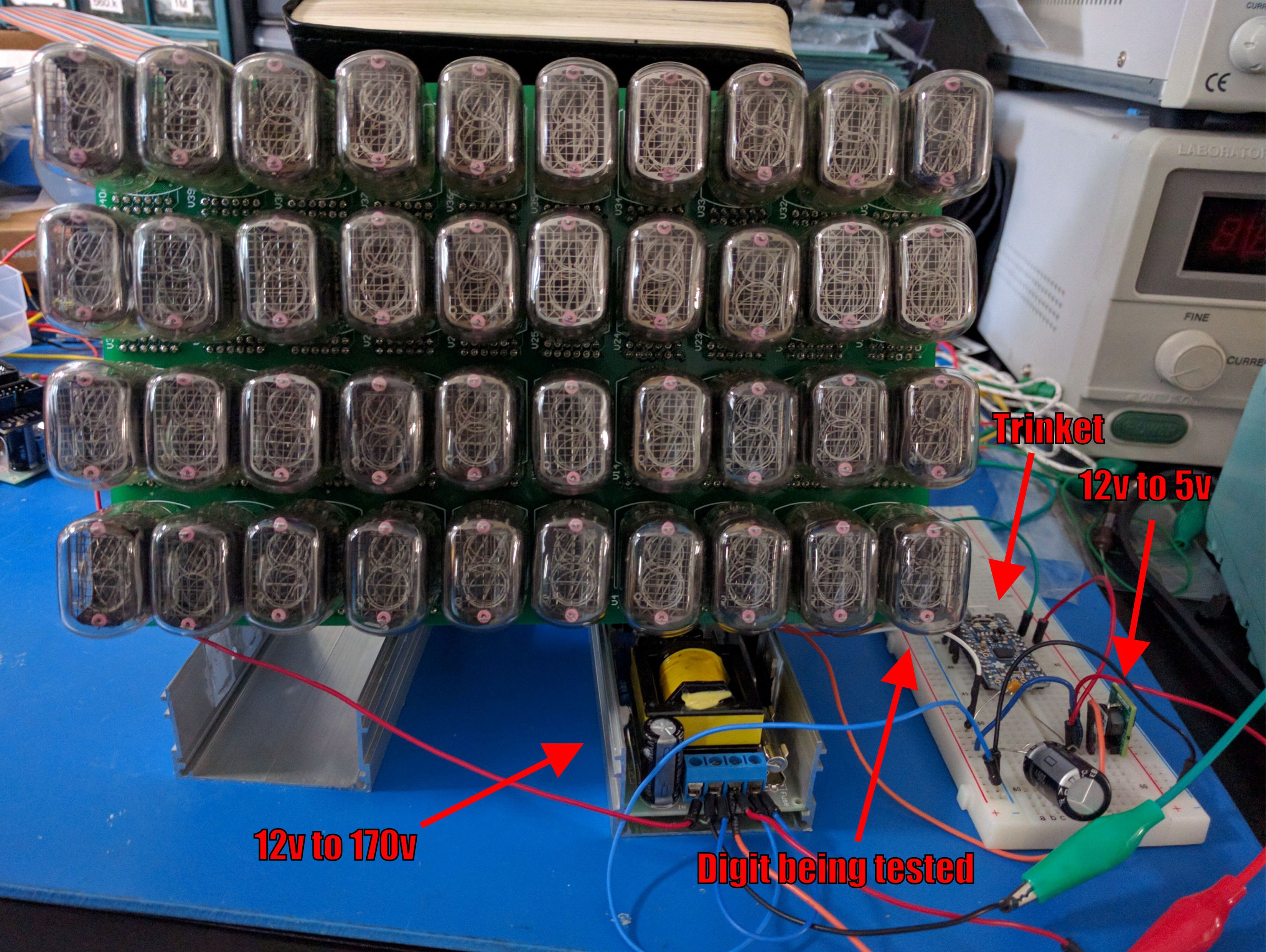
With the high voltage power supply sorted out, I wrote a quick Arduino sketch for an Adafruit 5V Trinket Pro to drive one Nixie digit via the pseudo-SPI. I am using a Murata OKI-78SR-5/1.5-W36-C 3-terminal DC/DC converter to convert the 12V input power supply to 5V for the Trinket and the driver board.
Normal SPI has clock and data, plus a slave select line which goes low before transmitting data, and high after the transmission is done. However, the VFD driver requires a latch pulse after the transmission is completed to latch the clocked-in data to the output buffers. Also, there is no slave select line.
The sketch goes through all the digits, and adds the latch pulse at the end of every transmission.
Note that there's a problem. When the thing powers up, the default state of the VFD driver output is low, which turns on a digit. Well, with all outputs at low, all digits are on until the Trinket starts and sets the state properly.
I will probably need a switch to disable the 170v line until the controller is ready.
Discussions
Become a Hackaday.io Member
Create an account to leave a comment. Already have an account? Log In.