 Chuck Glasser
Why is it that the simplest things sometimes turn into nightmares? I wouldn't call the vacuum table a nightmare yet, but it is certainly not ideal.
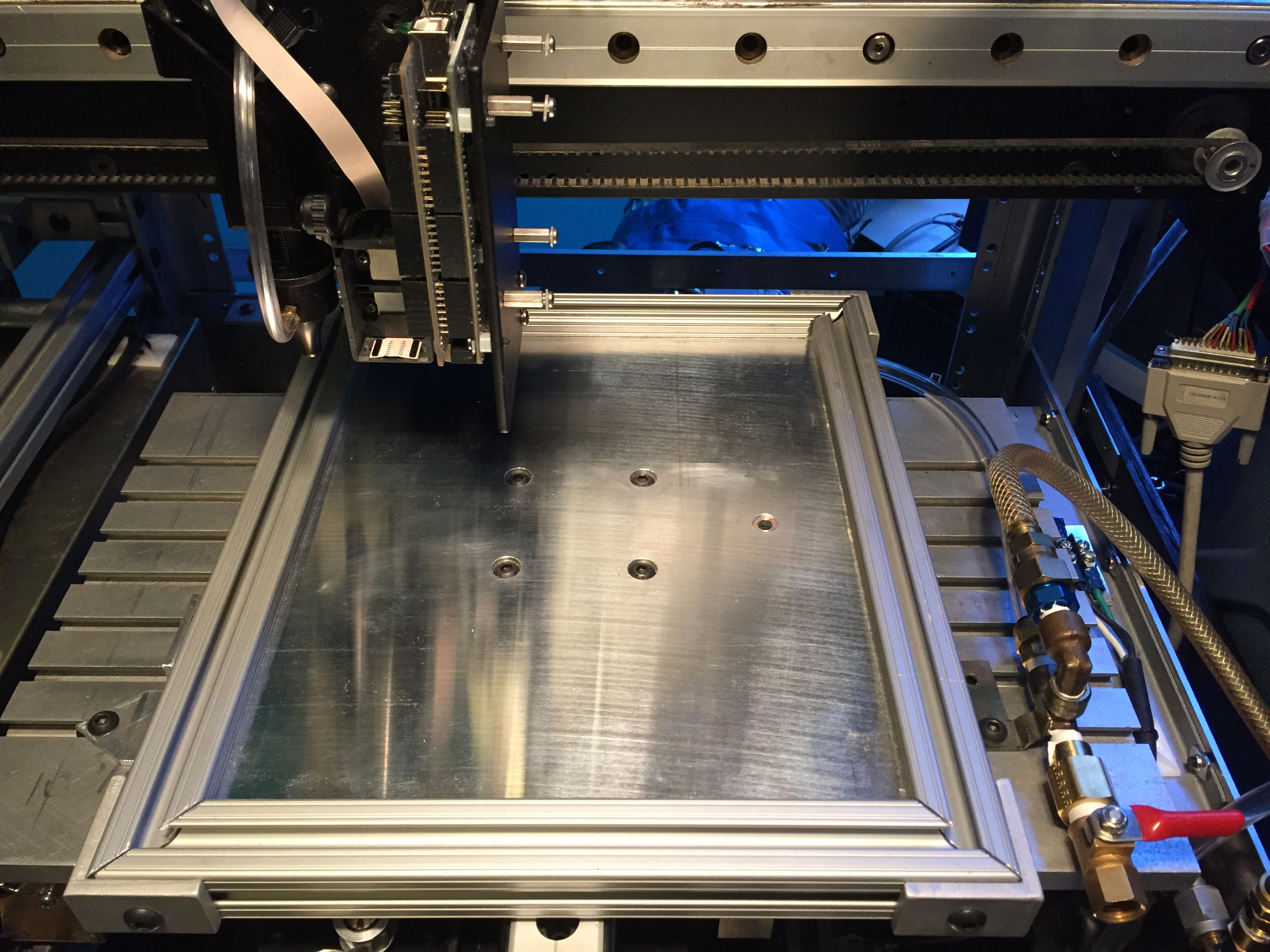
So this is a 1/4" thick sheet of MIC6 aluminium plate with a border of 80/20 T channel. it is very flat +- 15 mils over a 4x8 ft sheet! It is mounted to an additional Y traverse that extends the range of the main Y-axis bed to allow for the offsets of the large bed. You may recall a brief mention of the large bed in part one. Beneath the vacuum table is the main bed with 7 T-channels. Very handy those T-channels. Note how they were used to mount the air fittings.
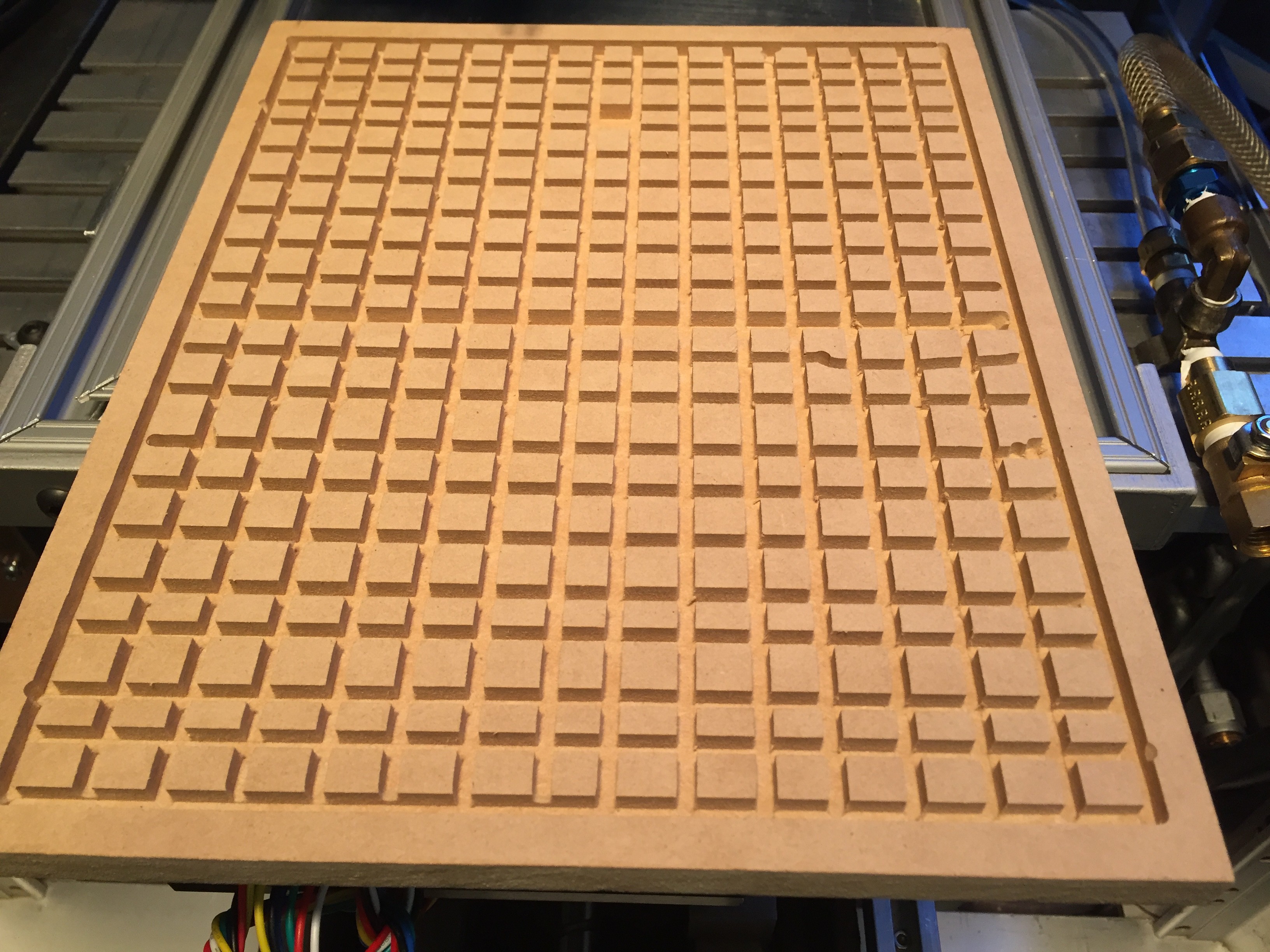
As it turns out, MDF is porous. If you pump out the air on one side of the material air will flow through the material. This is 1/2" thick Ultralite MDF, with a 4' x 8' sheet costing around $25.00. The groves distribute the vacuum over the entire surface. The difference in porosity between Ultralite and standard MDF is notable.
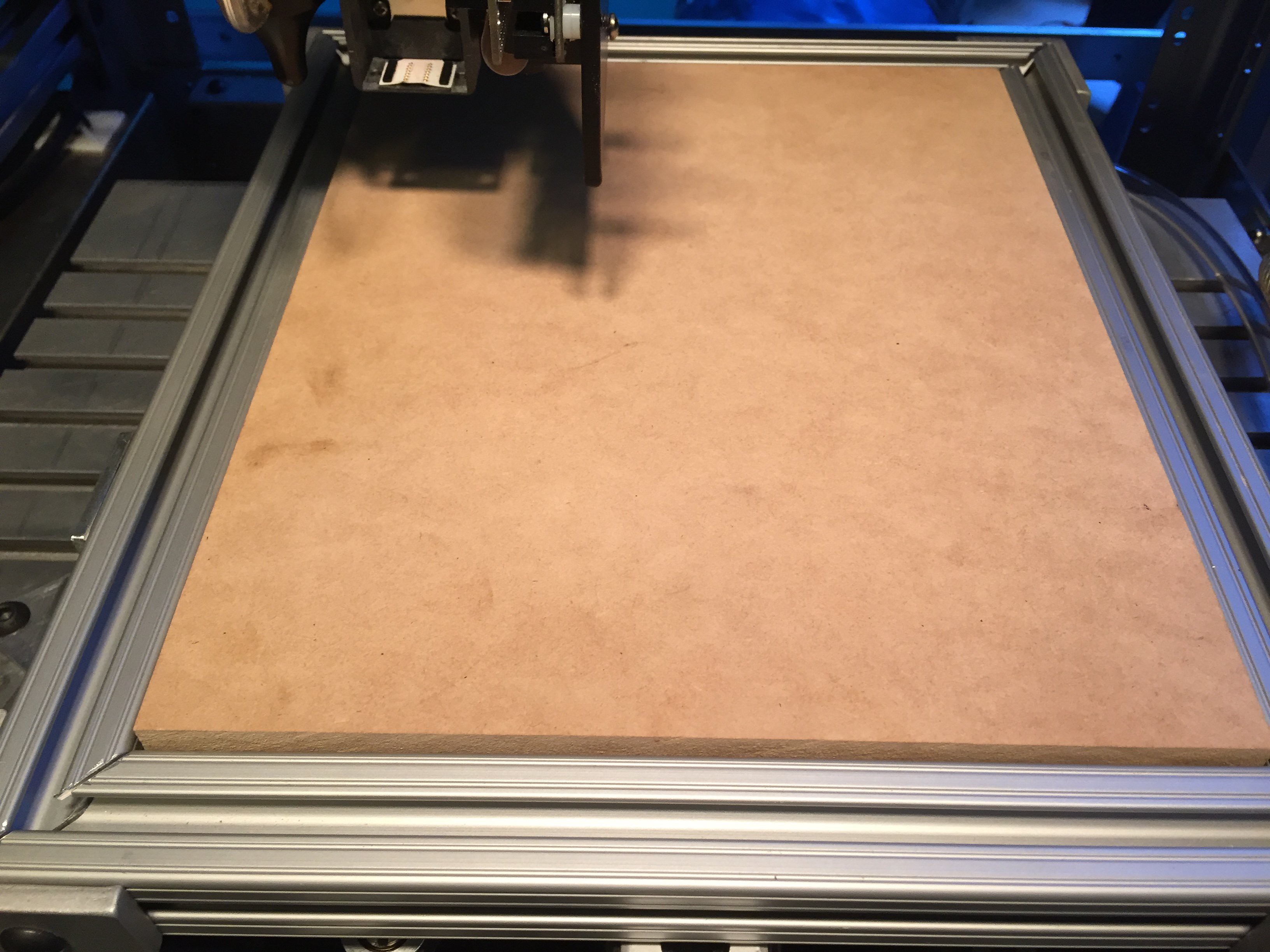
The Ultralite MDF mounted in the frame. Once the vacuum is on the sheet will not move. Neither will the ceramic sheet placed upon it.
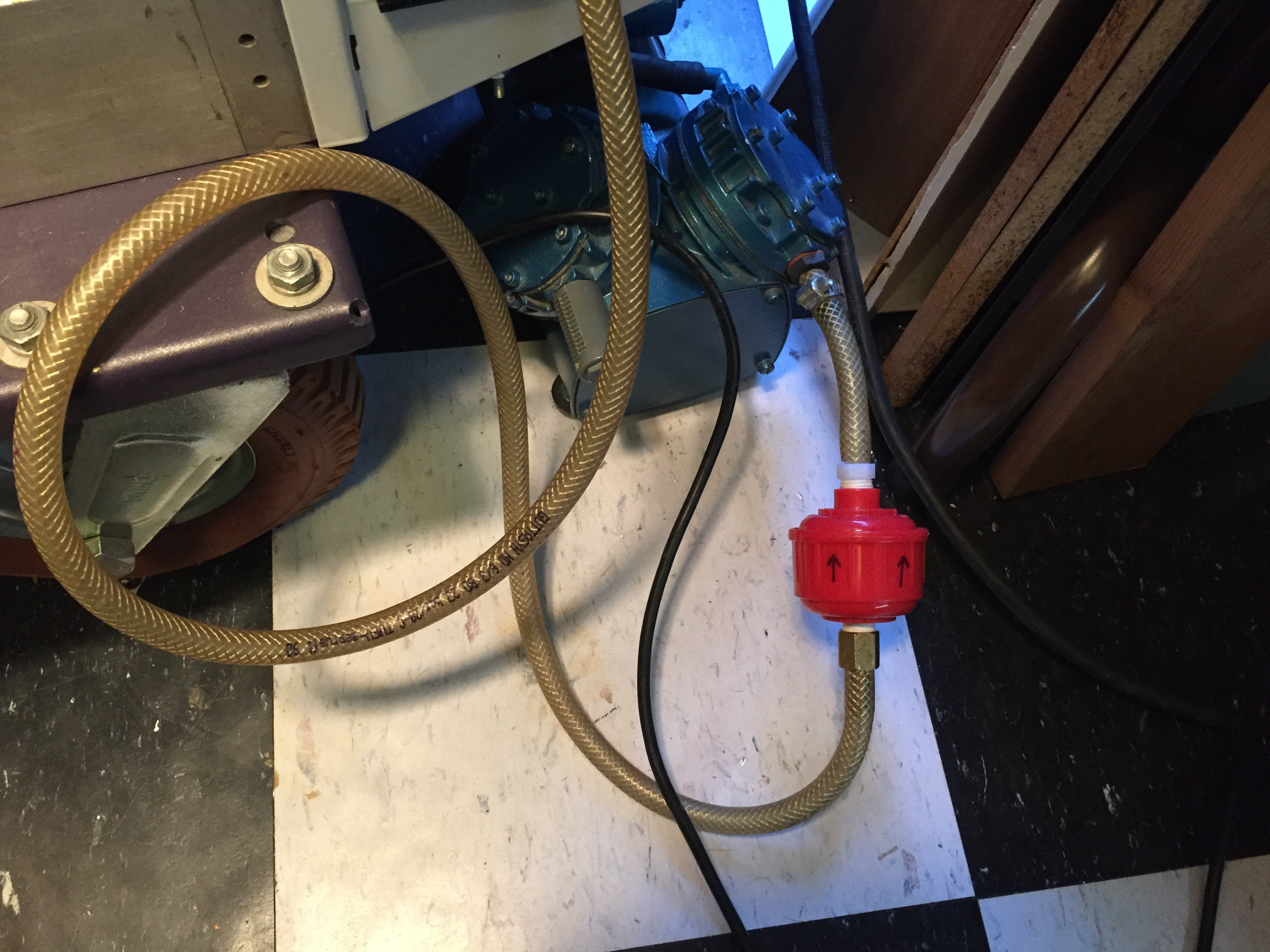
An air filter keeps the dust from the MDF out of the vacuum pump. Might as well avoid problems before they become a crisis.
So where is the problem?
While the vacuum is sufficient to hold the material in place, I would be happier if it was so strong that it was necessary to introduce bleed air to control the vacuum strength.
When the laser hits this material it is going to chew up the bed, so it will be necessary to replace it ... frequently. Good thing I got a 4' x 8' sheet.
It would be useful to have a ceramic bed made of fire brick or some other material that is tolerant of cutting power of a CO2 laser. No time to mess with it for now.
Discussions
Become a Hackaday.io Member
Create an account to leave a comment. Already have an account? Log In.