One of the drawbacks of the original design is, that it outputs a clock signal in one of the states.
I now have a different design that has a continuous high or low at the output. This will improve the useability of the circuit. Here it is:
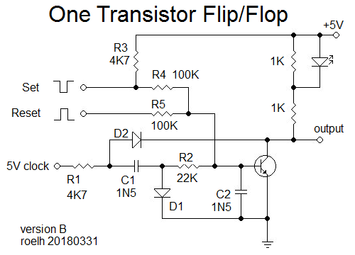
I also added set/reset inputs. It is tested with a 500KHz clock.
After a RESET pulse, the transistor will be conducting, output will be LOW (and the LED is ON). The low transistor output also pulls the right side of R1 to a low level (through D2), this kills the clock signal.
During a SET pulse, the transistor will have no signal at the base, so it will stop conducting. The output will become HIGH (and the LED wil be OFF). The right side of R1 is no longer pulled low through D2. So the clock signal will be passed through C1, and the right side of C1 will have a negative going waveform (below gnd) because it is rectified by D1. This waveform is low-pass filtered by R2 and C2, giving a negative bias to the base of the transistor. This bias is still present when the SET pulse ends, so the negative bias will still keep the transistor from conducting (closing the positive feedback loop).
During the next RESET pulse, the transistor will get extra base current through R5, and that will be stronger than the negative bias, so the transistor will be conducting again.
Note that R3 is not needed for the operation of the circuit, but it will make it easy to build a test circuit and have a SET pushbutton connected to gnd, and a RESET pushbutton connected to +5V.
Discussions
Become a Hackaday.io Member
Create an account to leave a comment. Already have an account? Log In.
I know that most users of this circuit would be using your higher clock frequency but was wondering how low have you tested it out. My IO runs between 1 and 100 Hz. I really do want to try this out and see where it leads me :-)
Are you sure? yes | no
Hi Dr. C. ! The circuit can be adapted to low clock frequency by making the capacitors C1 and C2 larger. If the clock is for instance 3000 Hz (easy to make with a transistor circuit), then C1 and C2 can be 100nF (I tested that with the first version only). The clock frequency and the C1, C2 capacitors are not very critical, a wide range will work.
This is all open to experimentation. I did not (yet) do an extensive search for which values will work and which won't work. But the following will apply:
A certain value for C1 and C2 implies that a certain minimum width is needed for set- and reset pulse. If the set- and reset pulses are shorter than that, C1 and C2 must be made smaller.
And also, a certain value for C1 and C2 implies that a certain minimum clock frequency must be applied. If C1 and C2 become smaller, the minimum required clock frequency becomes higher.
C1 and C2 do not necessarily have the same value, but I did not explore that. Also, in the current version the minimum required pulse width for set- and reset pulse might be different.
Are you sure? yes | no
Sounds good to me, I have never worked with any simulation software here except Logisim and what you just added gives me a good start point to work with :-)
Are you sure? yes | no