 Arya
AryaThis is a third day, and it was awesome. I received the base station. There's this teardown of a Merlin@Home EX1150. It sucks^W is not that good though, so I've made my own.
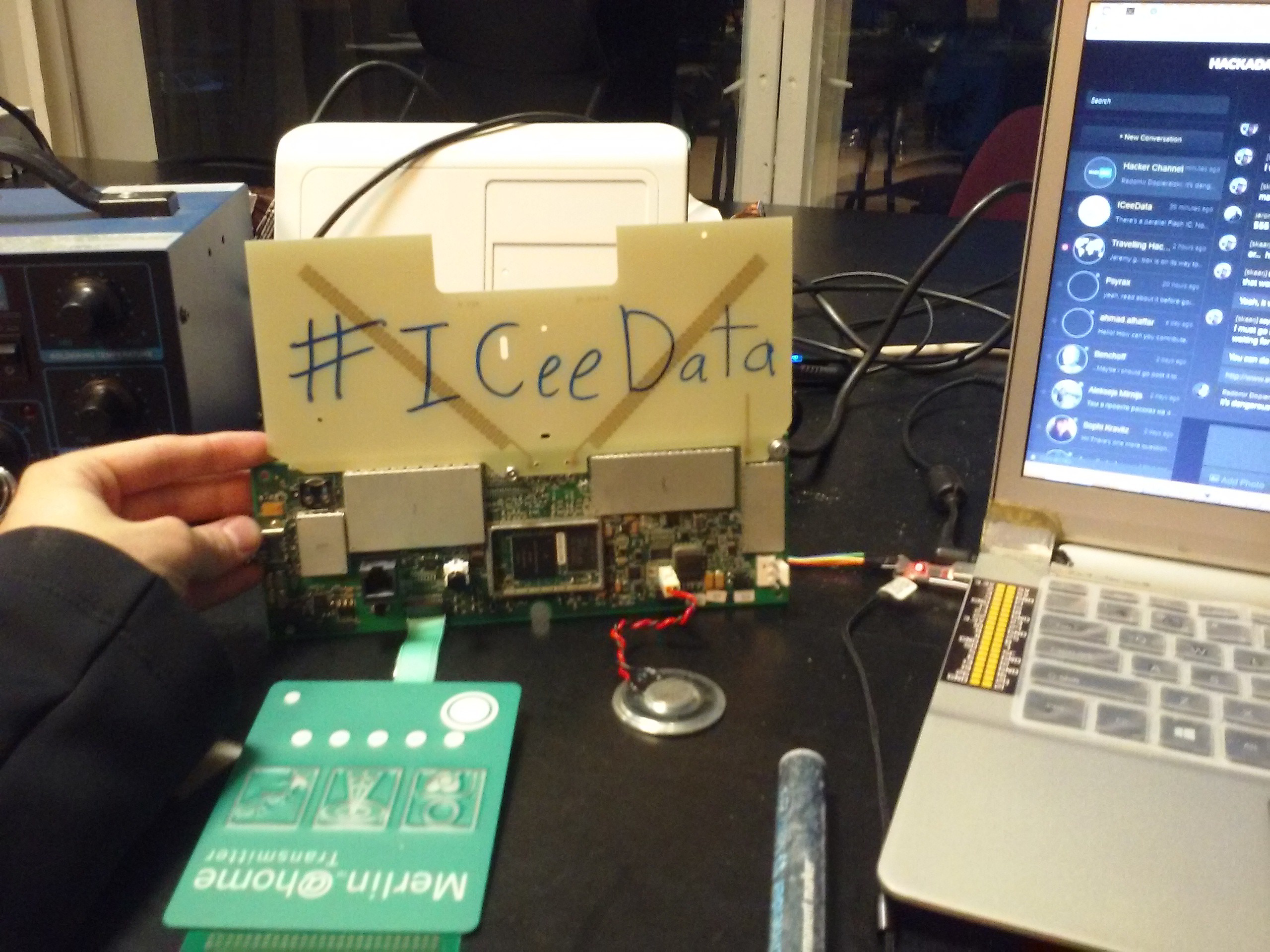
PWN'd.
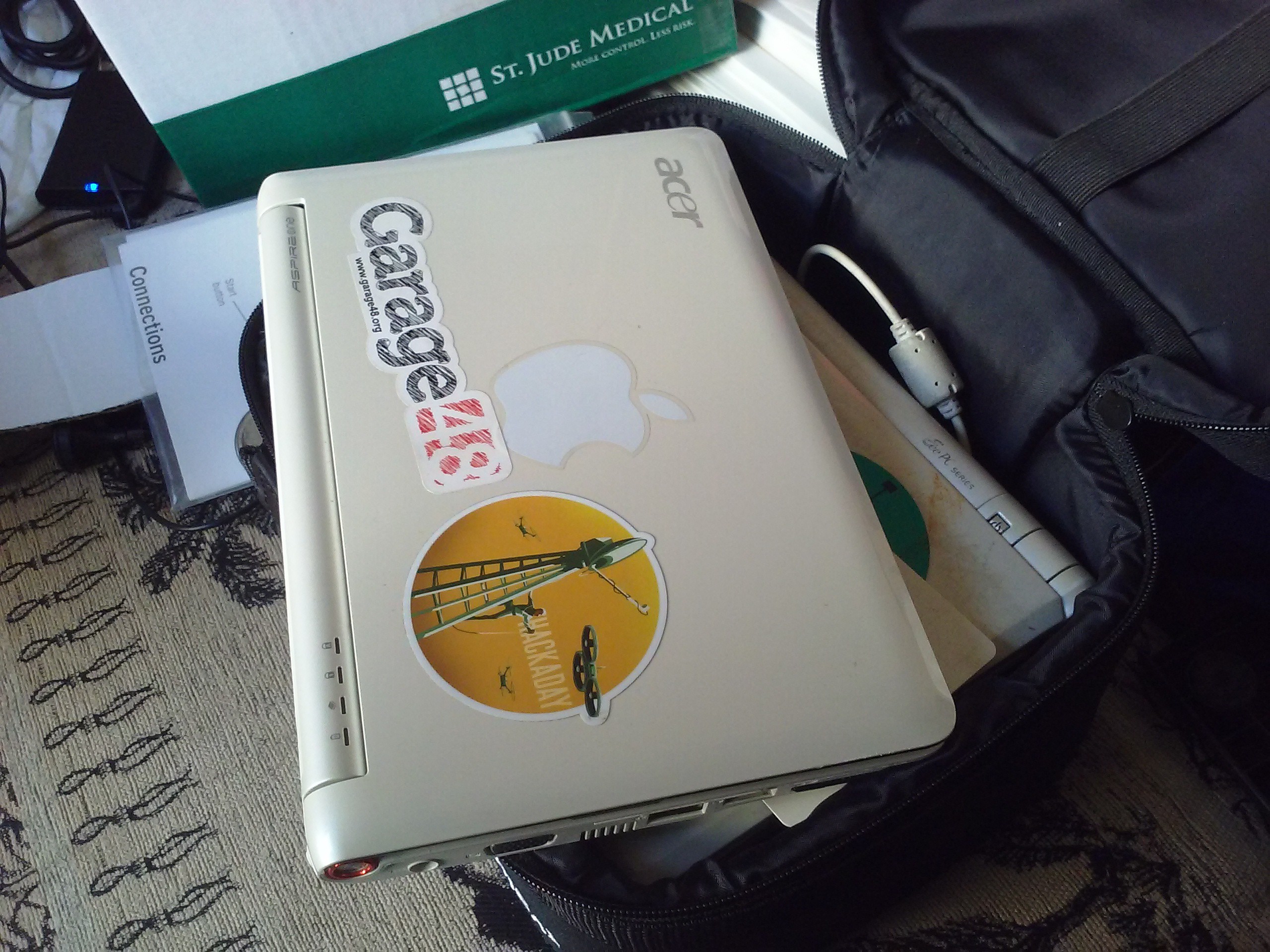
But first, look at this! This wonderful carry bag that base station was in can contain 3 netbooks! I need to buy more of those bags.
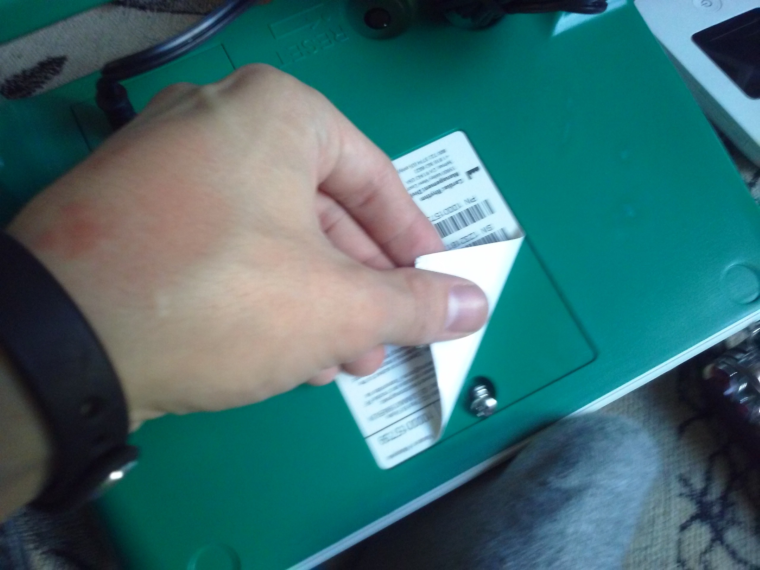
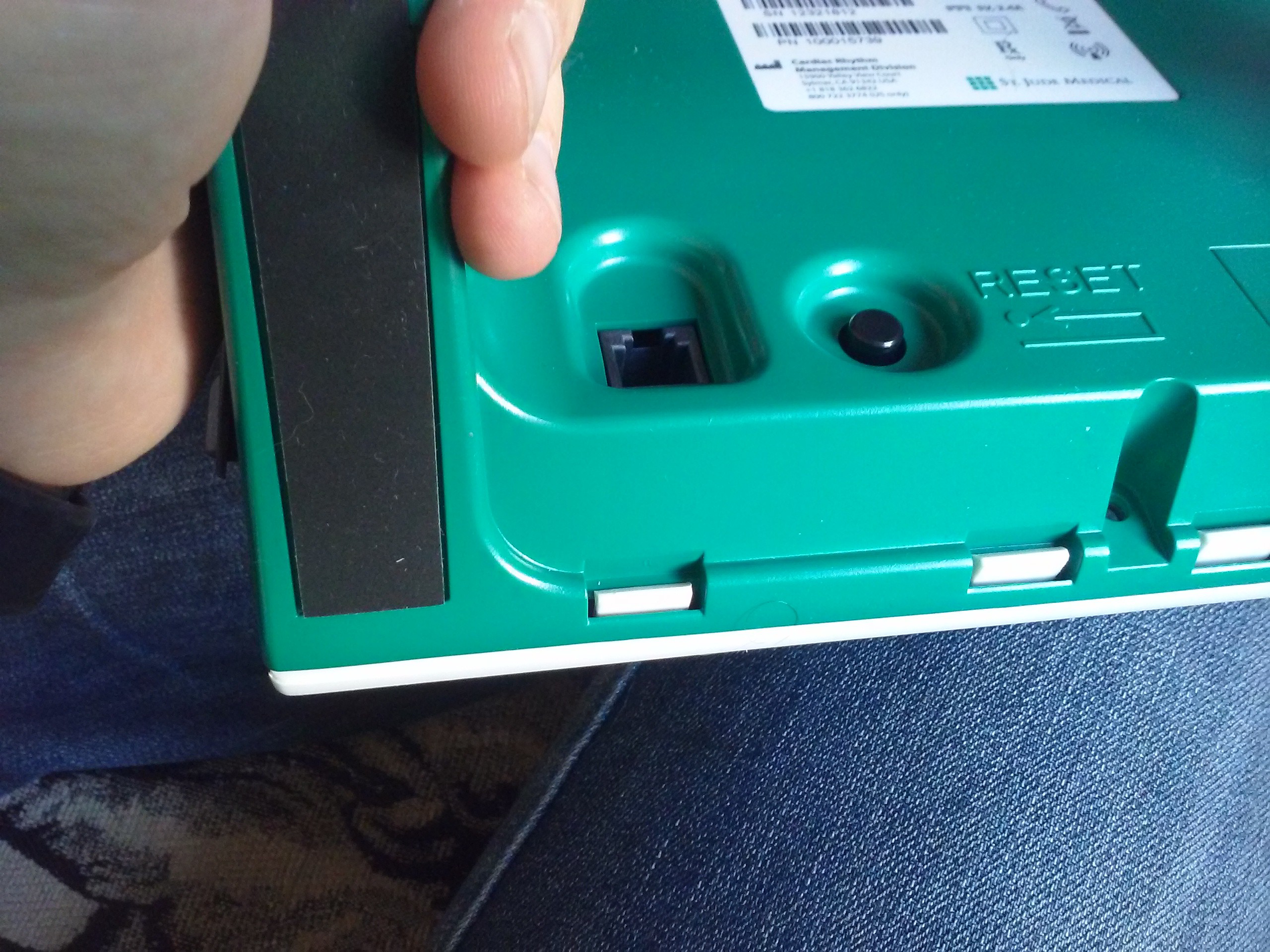
 Disassembling the base station is hella easy. After all, it's not made by Apple. There was a single screw that was not visible:
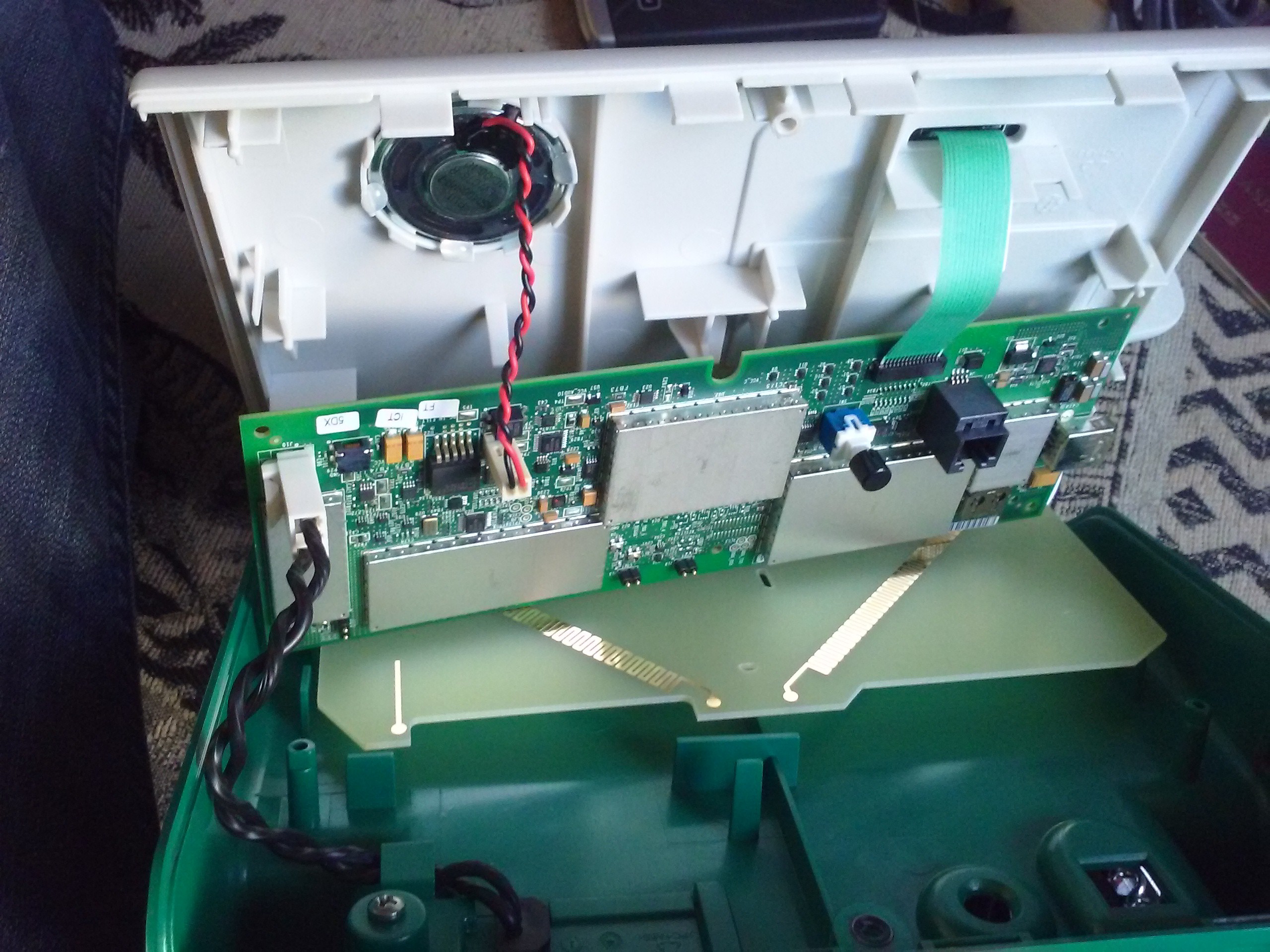
It consists of multiple parts. First one is the single logic board, with all the other parts connected to it,
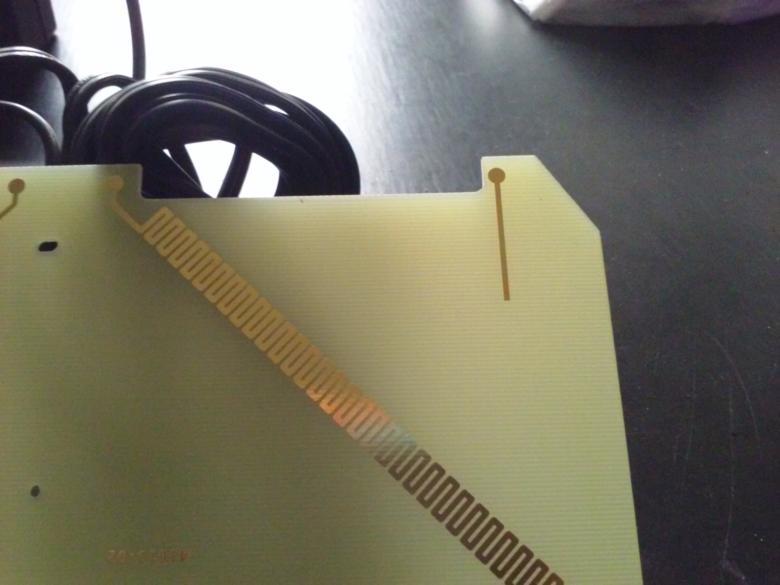
There's the antenna PCB. It has 2 402-405MHz antennas and one stub antenna for 2.4GHz.
 Then, there's the keypad. A bunch of LEDsand a single button. There's also the speaker. It's loud, even though not very much, but still annoying. I might need to replace that one with an LED, not sure how to represent different frequencies though. It's all powered by a 5V/2.5A PSU. I'll definitely have to power my Raspberry Pi from it once everything's over. I mean, it must be a medical grade PSU. Those things are *reliable*.
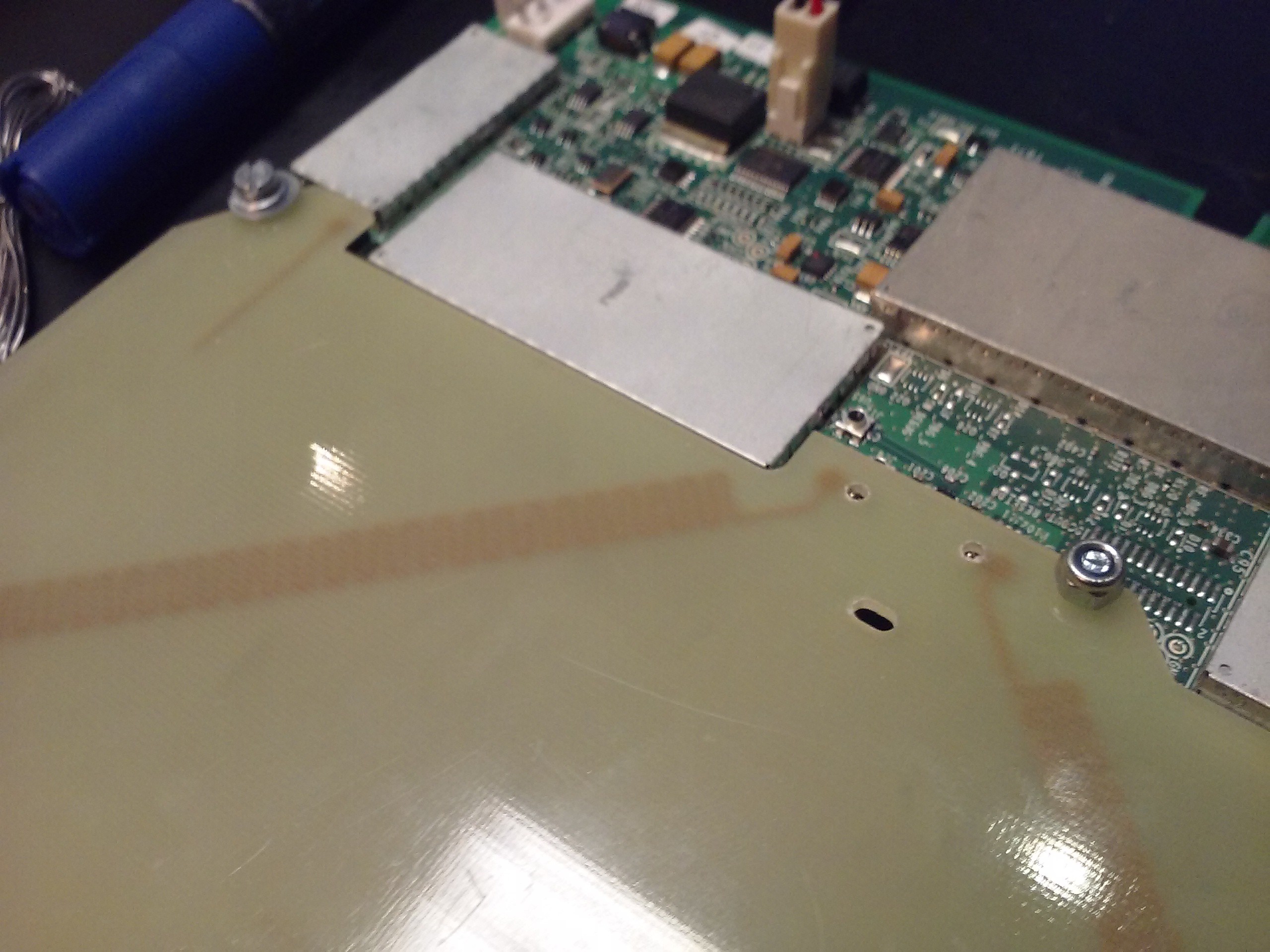
The outer shell is nice, but not for me. I need to have access to the testpoints (oh, the testpoints!), and I need to make sure antenna is always connected to the board - don't want to see how the transmitter behaves when antenna is not attached, it might be not what I want from it at all. So I needed to attach the antenna board to the logic board - that's usually done by the case, pressing them together from both sides, there are pogopins on the logic board which simply go to the antenna. So, I need to drill some holes and insert some screws to hold it all together:
Ready. Oh, overview of the logic board. Time to remove all those shields!
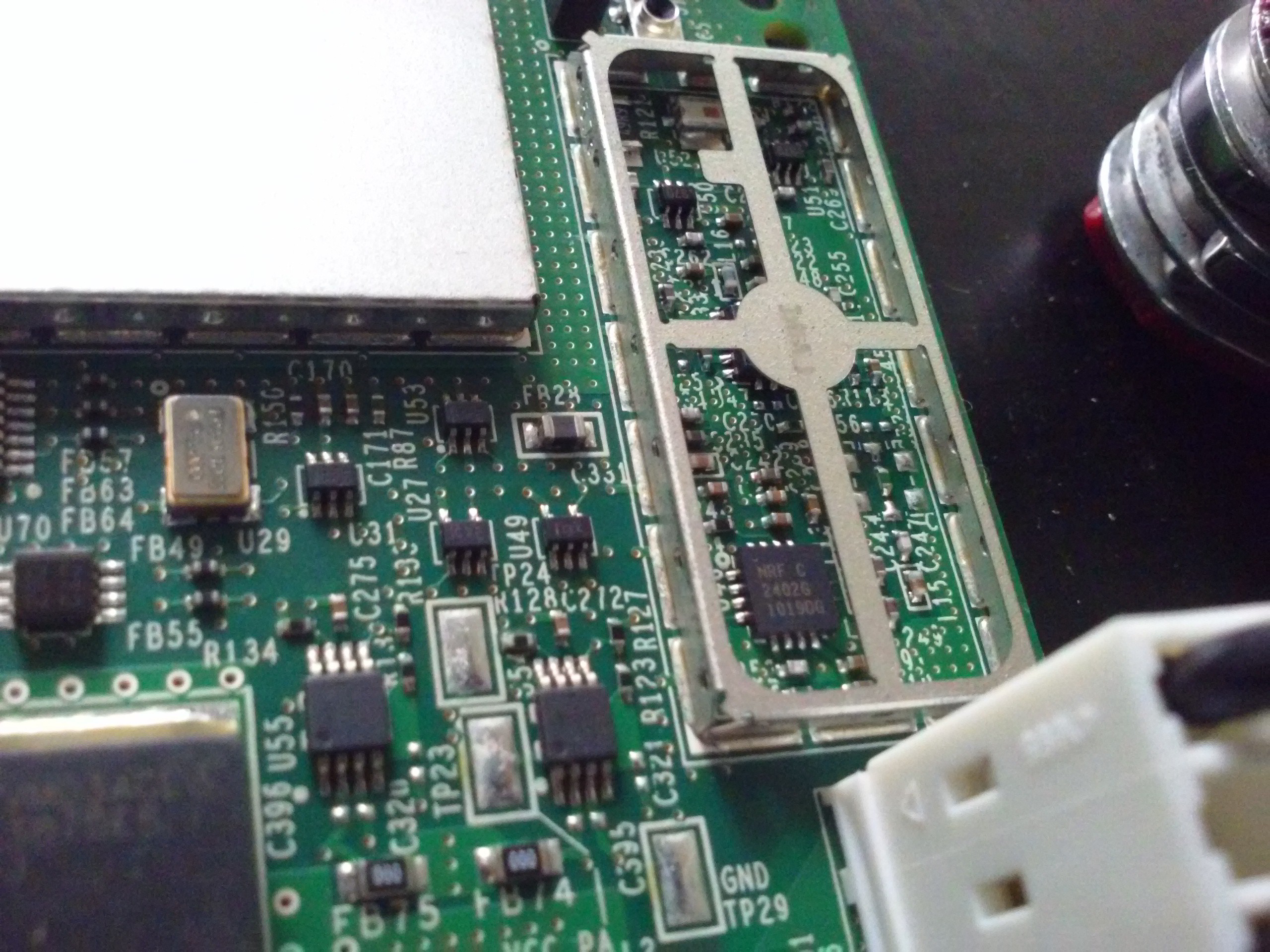
Here's the 2.4GHz wakeup signal generator. Implemented using a NRF2402G. Interesting!
Here's our Zarlink ZL70101A chip. Nice to meet you! I wonder if its counterpart seated inside pacemakers looks the same.
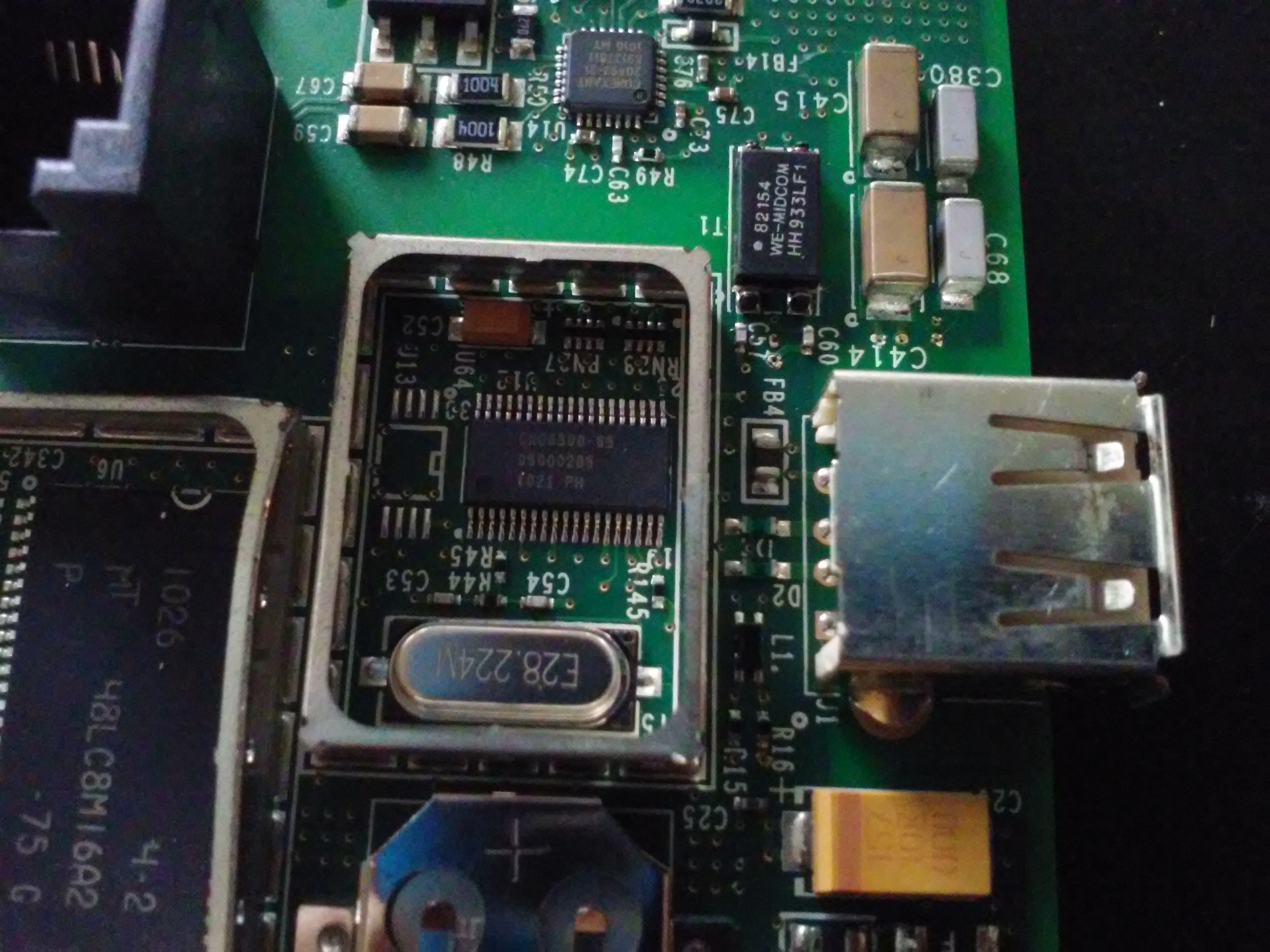
Here's some kind of weird IC under a shield near the RTC battery and the ADSL connector. Next to it (upper) is what seems to be an ADSL modem.
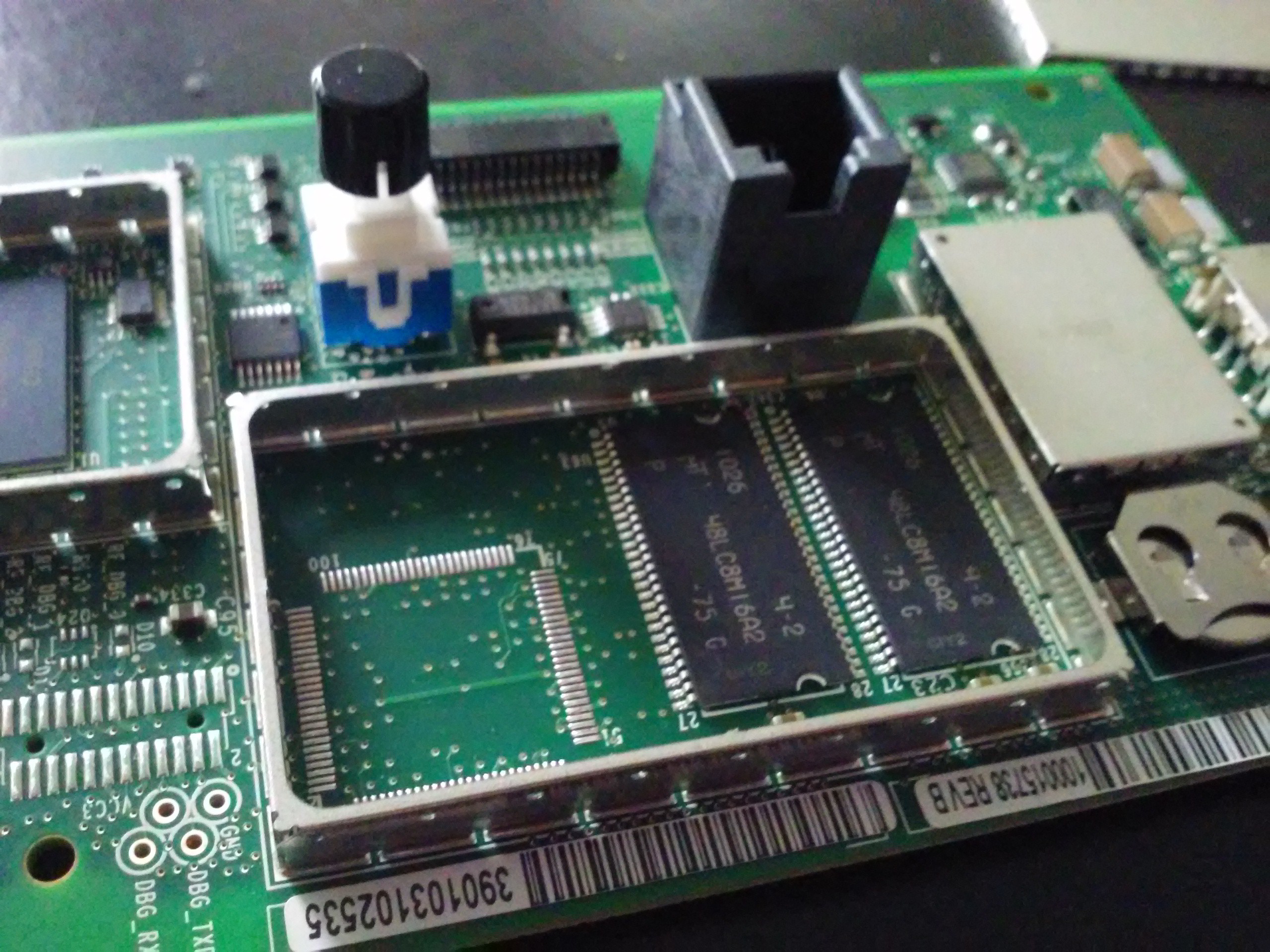
Some RAM chips. I wonder what they could have added in that unpopulated footprint.
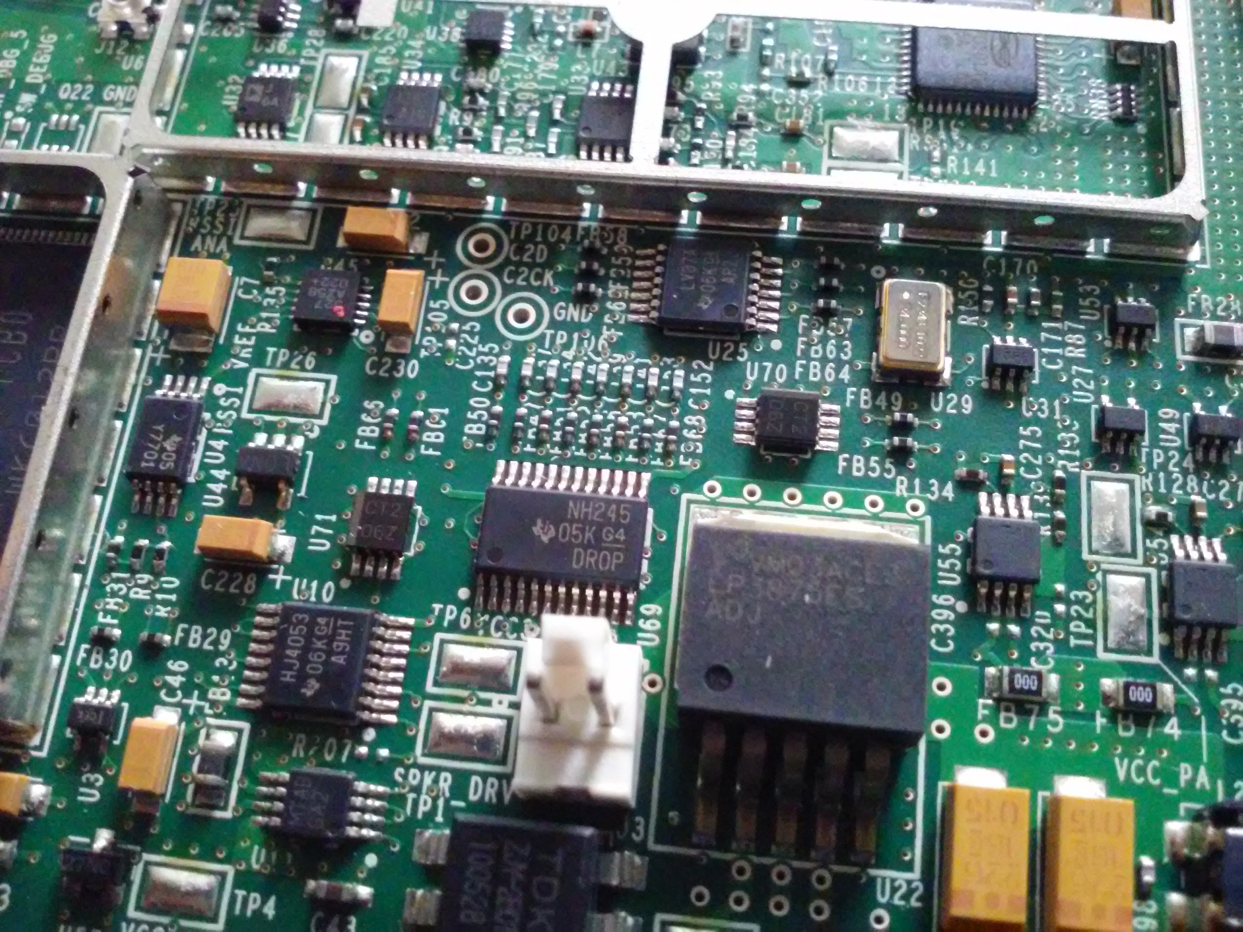
Power regulator(s) and, possibly, audio amp for the speaker.
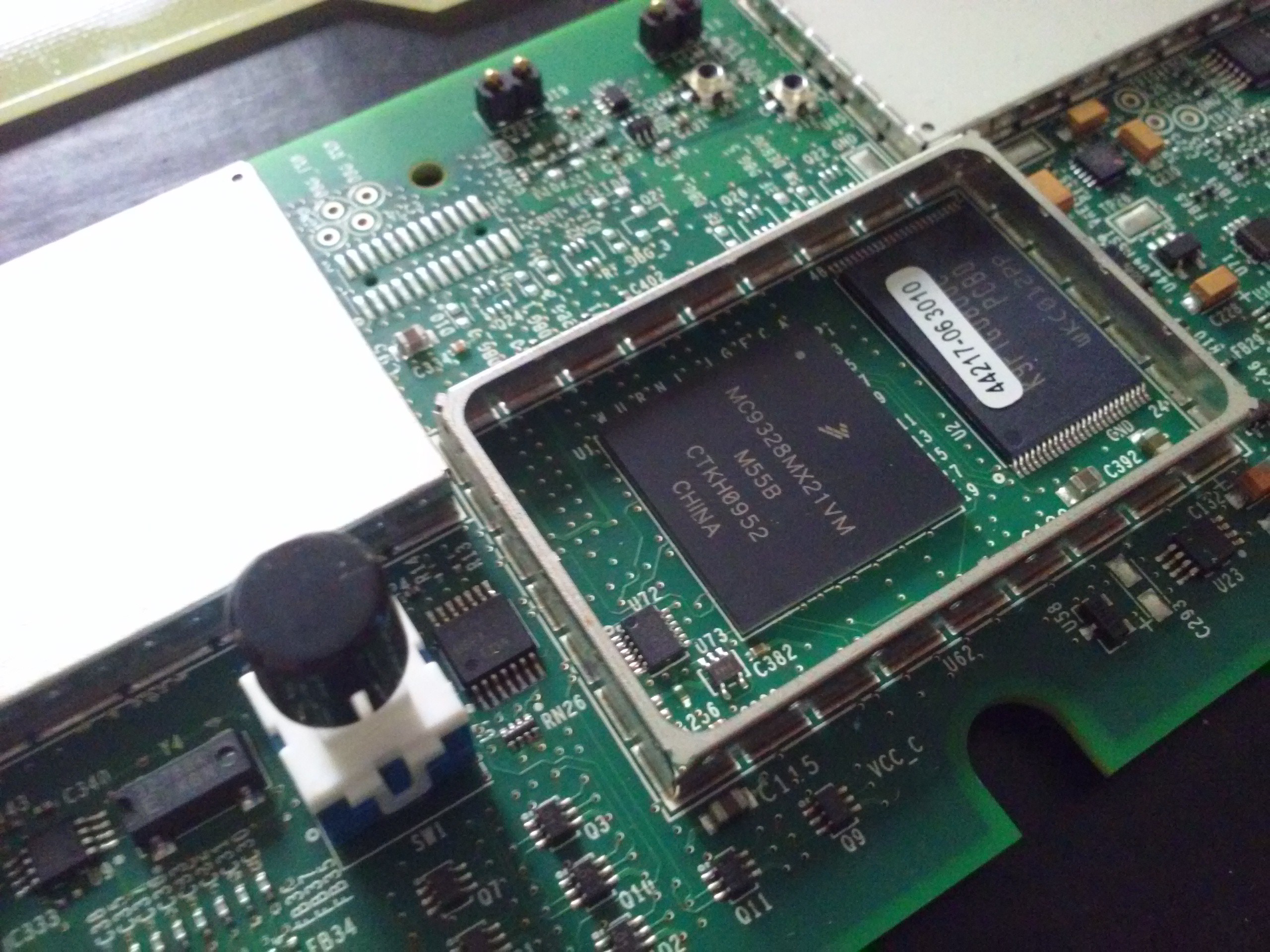
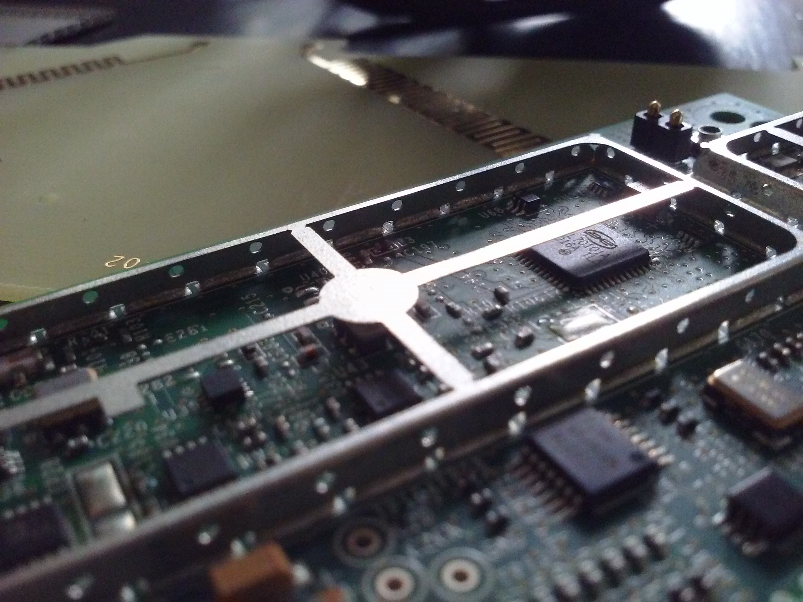
Main CPU (MC9328MX21) and its flash IC (K9F1G08U0C). Parallel flash. Shucks! I'll need to dump that flash contents, that's for sure. Meanwhile, let's look at other components:
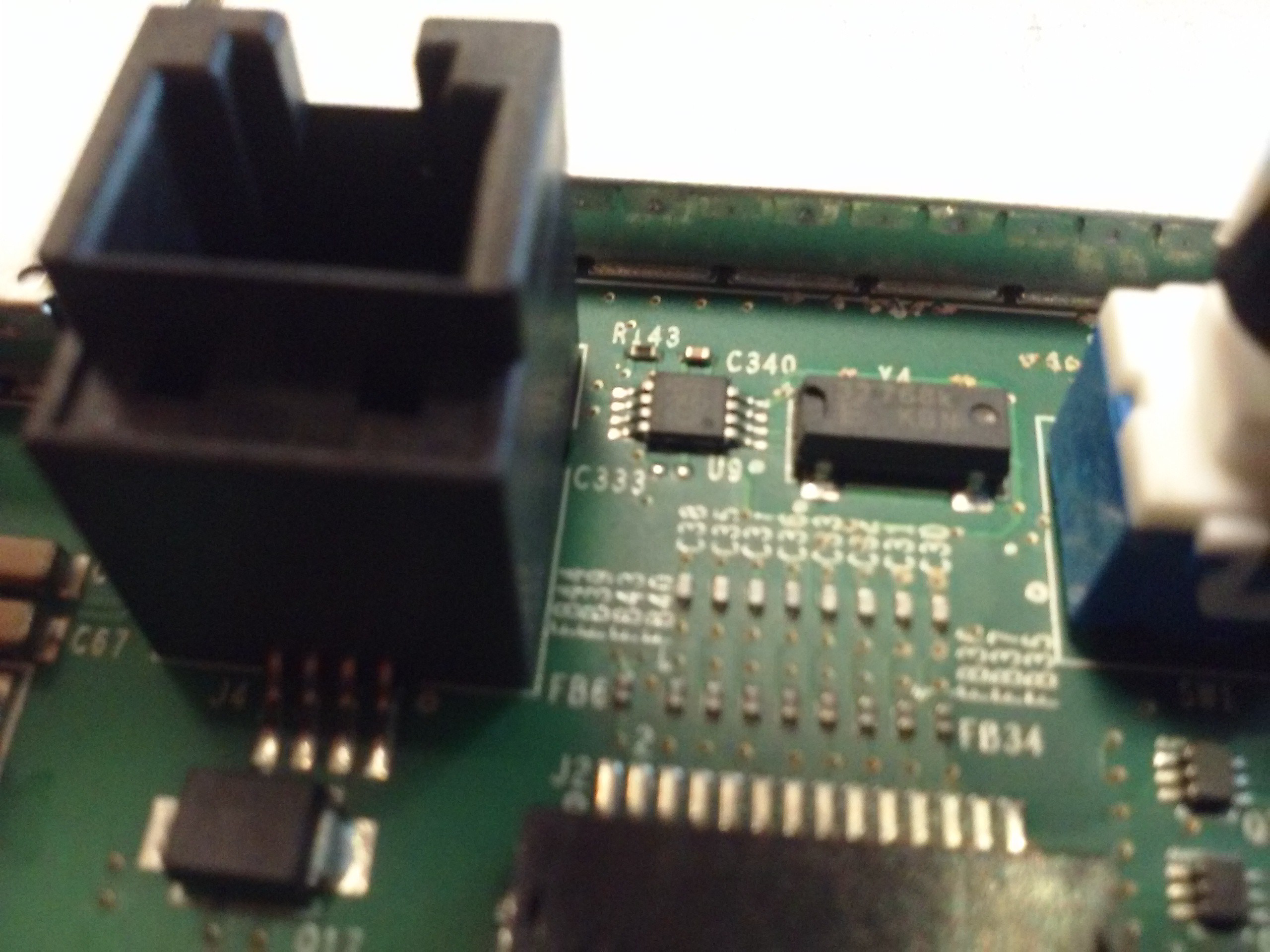
A DS1339 RTC. The battery is connected to it, I've checked. I accidentally shorted out the battery VCC to ground while taking off a shield and now the clock is reset to 1970-01-01 =( I wonder if I could program it in-system... There's always the problem when you end up powering the whole circuit while trying in-circuit programming and you can't program a thing because CPU has already taken the bus and won't give it back peacefully.
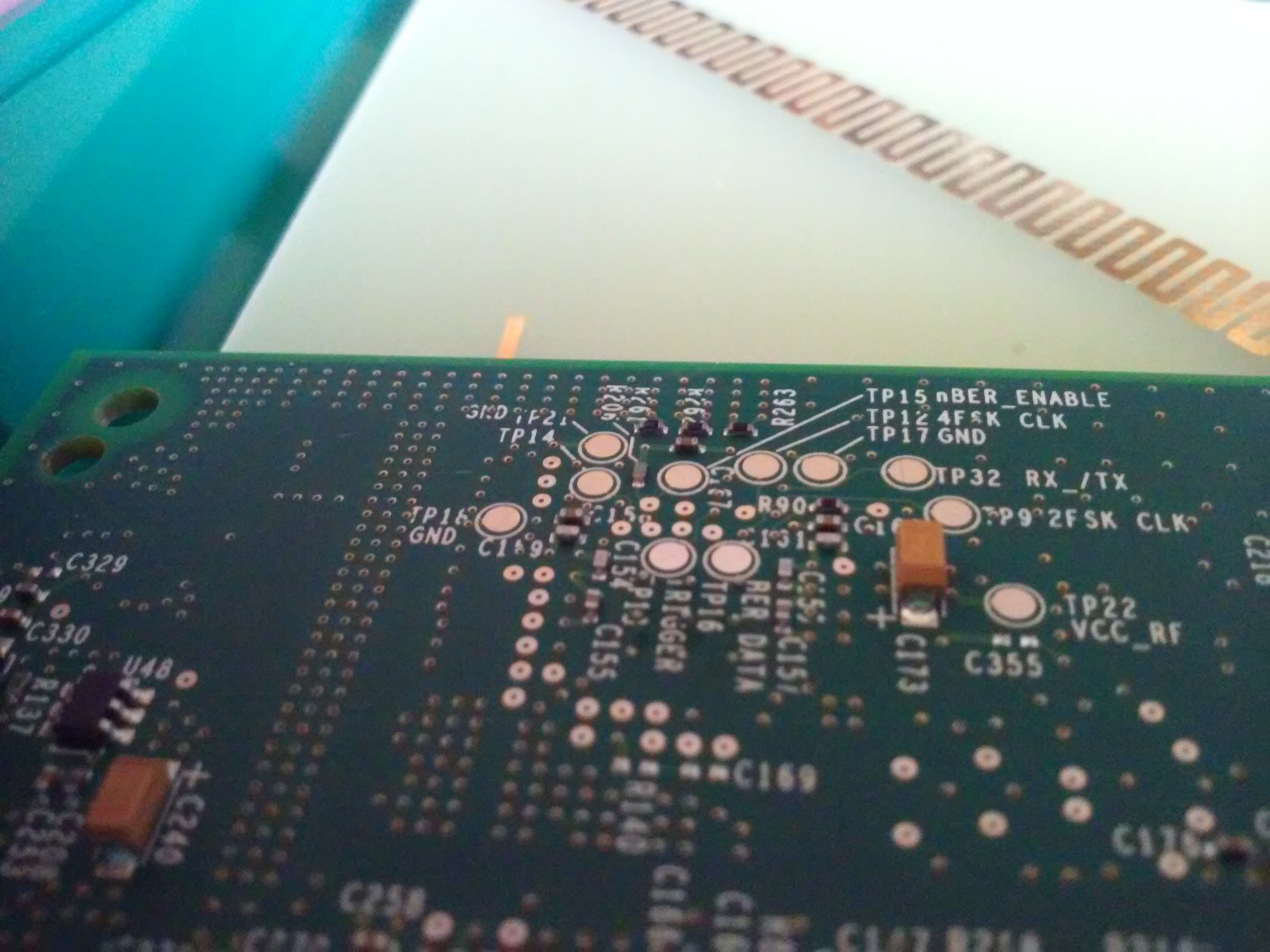
Testpointzzz!!!
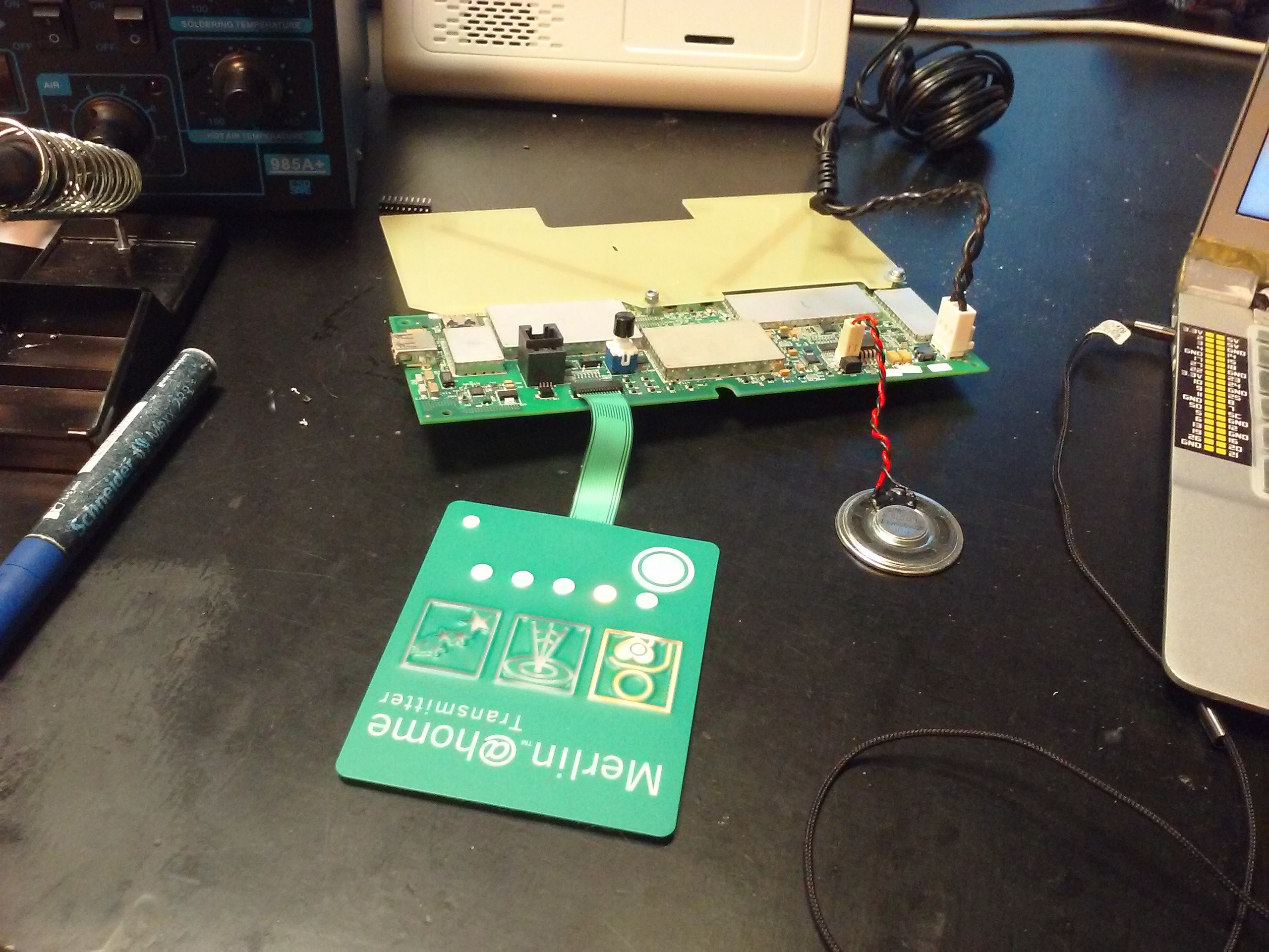
Everything's attached as needed, just that the case is out of the equation. Powering it up - it works! Not so sure about the radio part, will test that one, but LEDs light up and speaker beeps, all as expected.
Now I'll try the UART header. Oh, I didn't show you, did I?
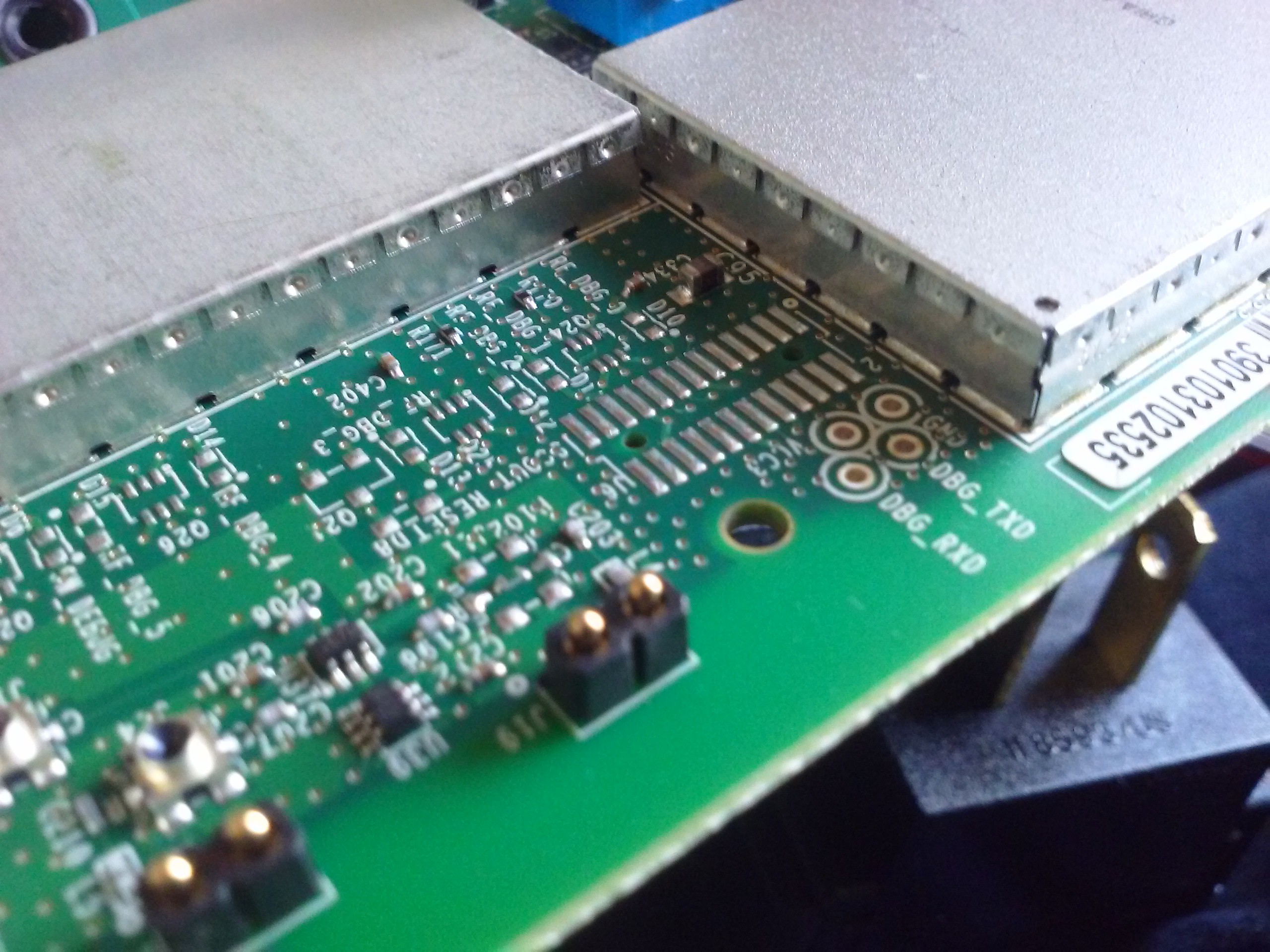
Here is it. It's weirdly-positioned, as you can see. However, you can insert 2-pin 2.54 headers just the right way so that they hold in there without soldering anything.
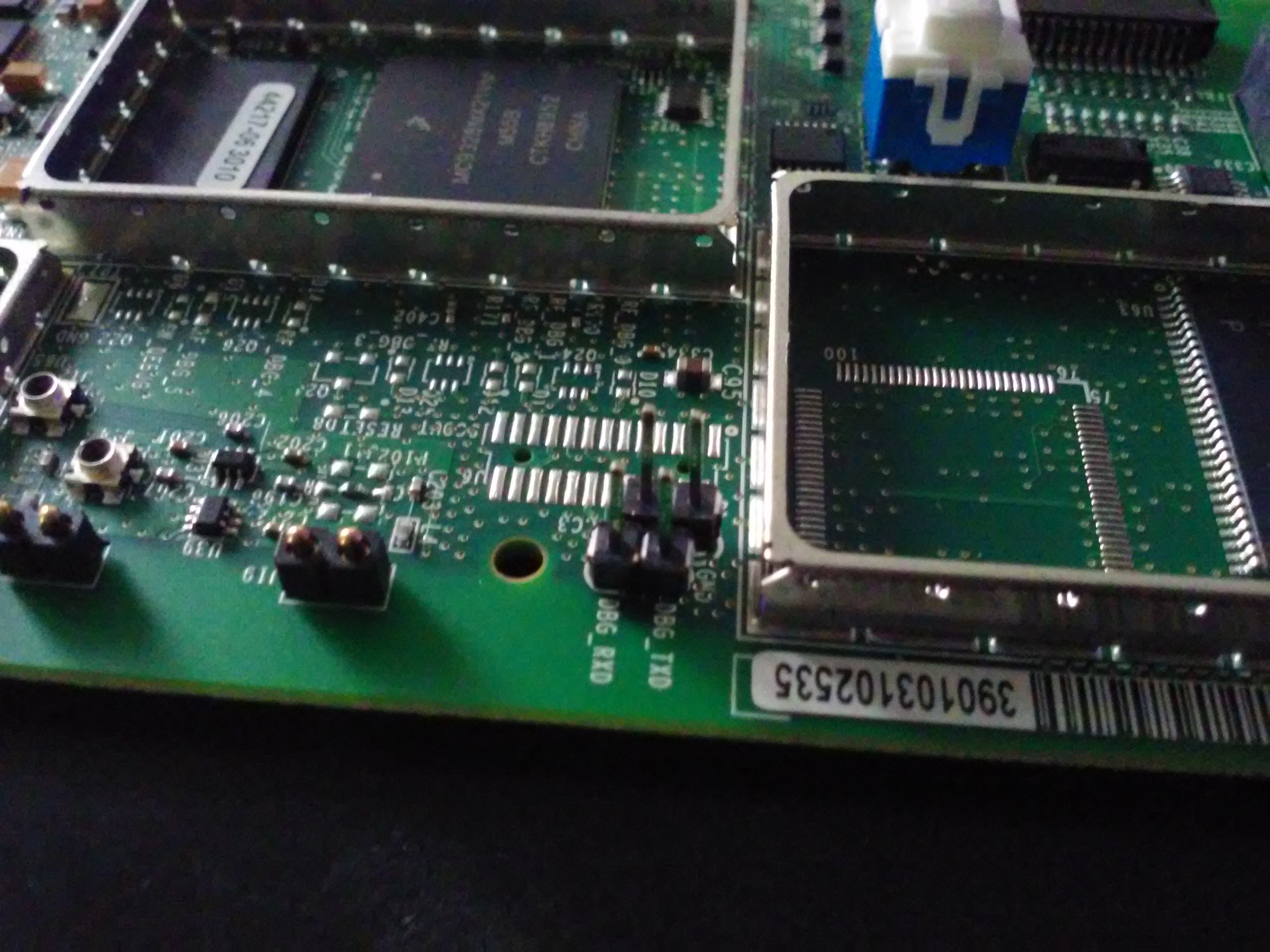
We have VCC, RXD, TXD and GND. No need to use VCC, that's for sure - I'll just connect 3 of them to my UART adapter. I tried 115200 rate, 8n1 (default) and this is what I saw:
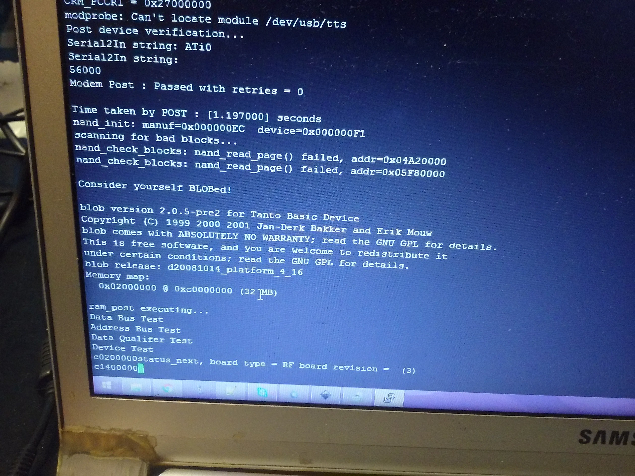
Yeah, Linux. Altough I was more like "Fuck yeah, Linux!" I was thinking there would be a possibility it ran some entirely custom firmware, but the odds are in our favor. What's the problem then?
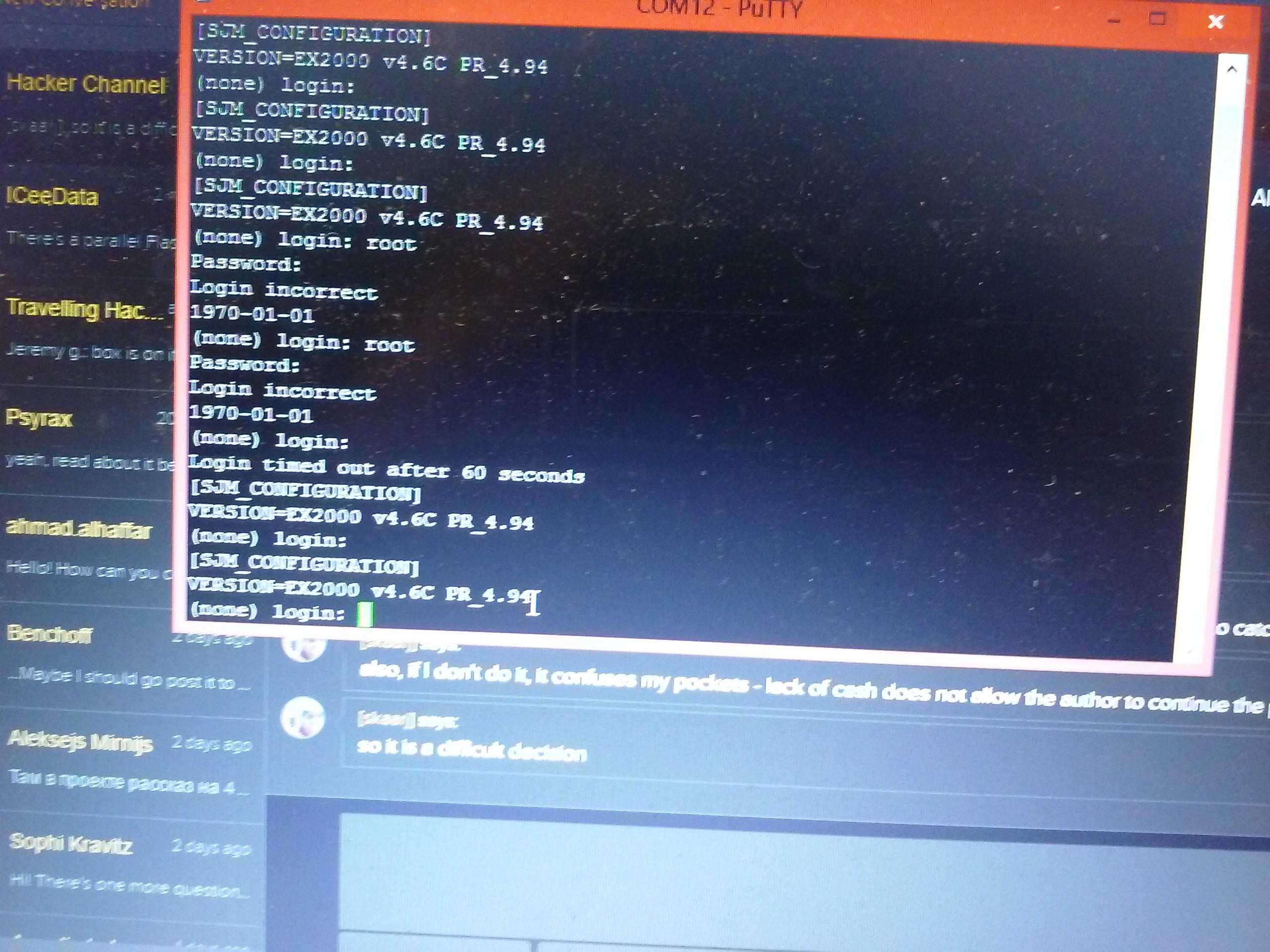
Login&password.
There's also a bootloader. This thing uses BLOB instead of, for example, U-Boot. It's accessible and I could dump the firmware... If there was a network interface to dump it through! I wonder if it'd dump it over UART... Oh no it won't. I'll need to go through the options later.
This password is the next frontier on our hardware hacking route. Once we get the login (very likely to be 'root') and the password (will need hash bruteforcing), we're in and can see ins and outs of how this data is processed. For that, I thin we need to dump the flash IC. Here's a good theoretical explanation with some tools included, and here's a @Sprite_tm take on this task, which I'll most likely follow =)
I think we should make a Wiki project about our development. Hackaday.io projects are great for telling a story, but Wiki will be more comfortable at some point.
Discussions
Become a Hackaday.io Member
Create an account to leave a comment. Already have an account? Log In.
Super!!!
Question: does that boot loader have any interactive prompt to pass parameters to the kernel? I may have an idea...
Are you sure? yes | no