 T. B. Trzepacz
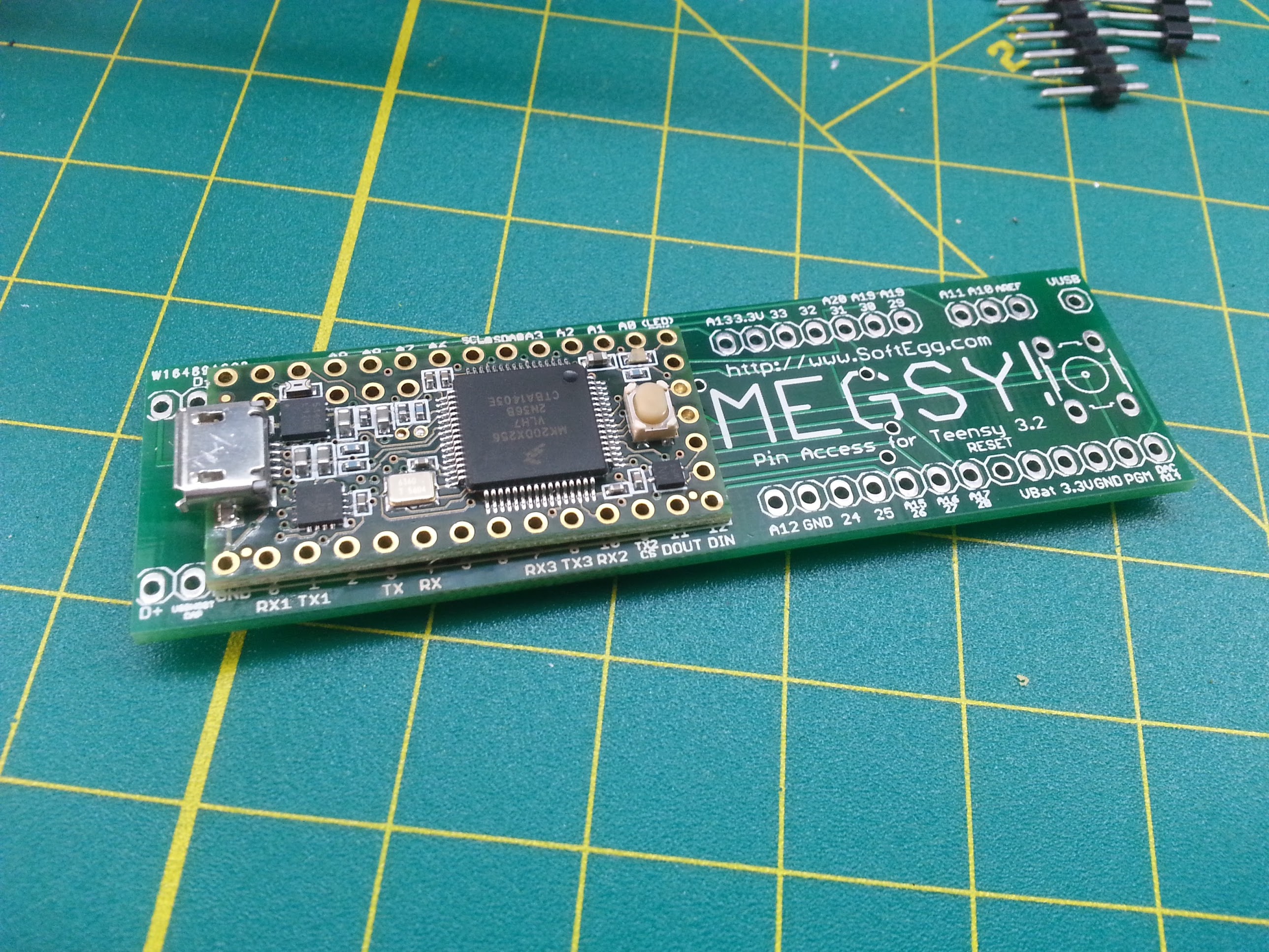
So I finally had a chance to assemble a Megsy based on the PCBs I had manufactured by PCBway. The PCB was designed to be assembled as a sort of "poor man's BGA (ball grid array)" where you would place one board directly ontop of the other with solder inbetween and melt the solder by heating up the vias. That plan did work, but not quite as intended.
So my first mistake was using plain-old solder as you use for through-hole soldering, instead of using the solder paste that is used for surface mount components. I have zero experience with surface mount, so how could I know? The regular solder is a solid when heat is not currently being applied, which means that after I tinned the pads on both boards, they would not sit flat against each other. This made it very, very hard to get the solder up to the 650 degrees Fahrenheit needed to melt the solder. The idea was to apply a soldering iron to the plated through-hole on each pad to heat the solder on the other side. That is fine, but in order to get all of the pads to connect, I would have to heat them all at once, which cannot be done with a normal soldering iron!
What to do?
Well, since I have started my residency at the Supplyframe Design Lab, I have access to their nice rework tool, a sort of heat gun for doing surface mount components. Knowing that I needed to melt solder at 650 degrees Fahrenheit, I turned up the temperature as high as it would go, 500 degrees. Unfortunately, I did not realize that, unlike the soldering iron, the temperature was in Celsius, not Fahrenheit! So I was actually heating the board up to nearly 1000 degrees Fahrenheit! This became evident when the board started to blacken and bubble!
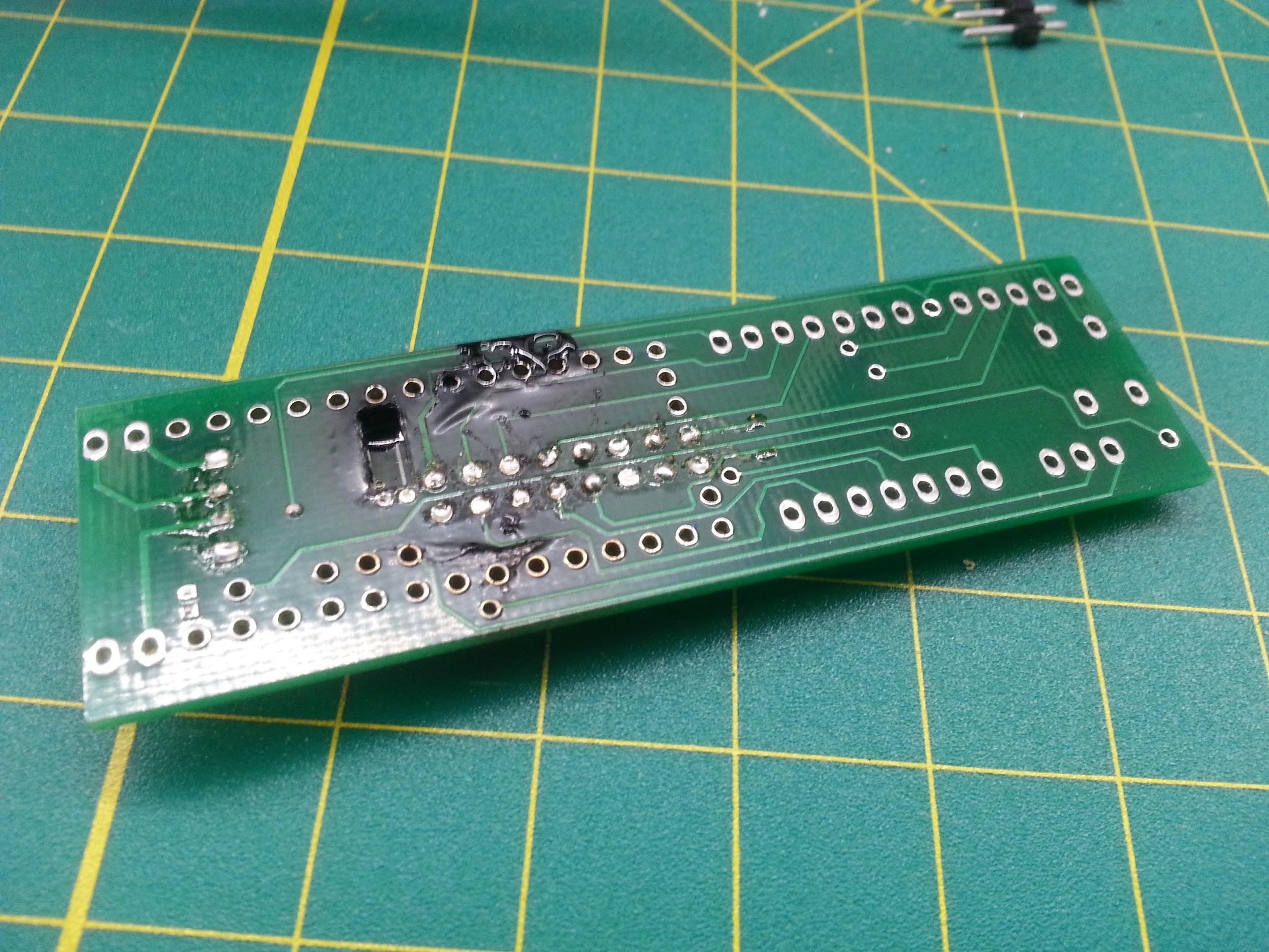
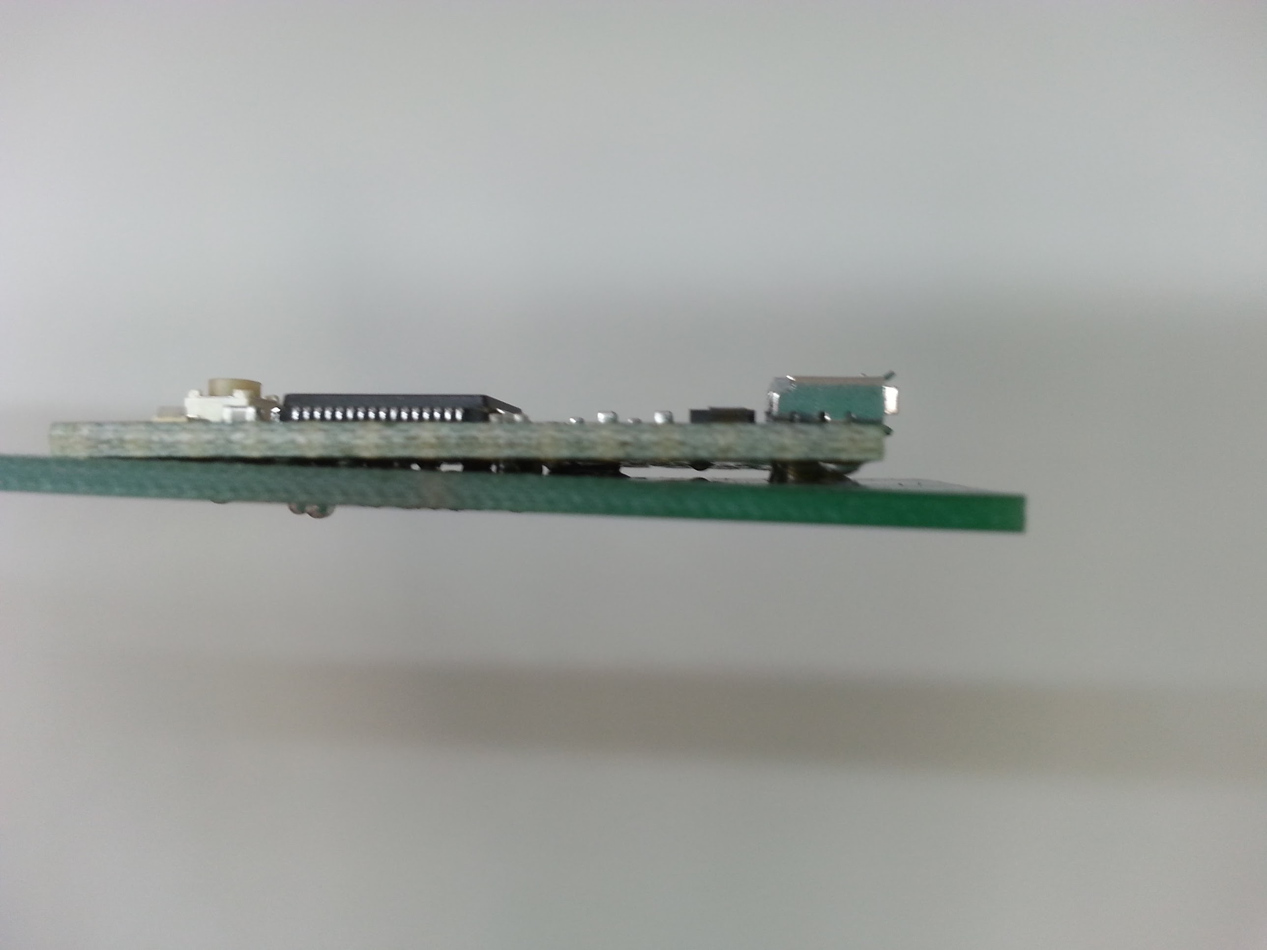
Oh my!I was worried that at I might have destroyed the board and the Teensy 3.2! At very least, surely some traces would have been rendered unusable, right? And the board was still not completely seated, because I couldn't apply pressure to the Teensy by hand with all of that heat going on. Or could I?
I grabbed some tiny binder clips from the stationery cabinet and put them on the corners of the Teensy board, and then applied heat again. Again, the board started to bubble and smoke. But the Teensy did settle a bit before the other lab occupants, alerted to my transgression by the smell of burning circuit board, suggested that I stop. I could feel their disdain; my first day and I've already surely fried a perfectly good $20 microcontroller! The horror!
 Or did I?
I plugged the Teensy in, and it ran the intro flash sequence OK, and the computer did report a driver connection when it attached, so perhaps all was not lost.
At their suggestion, I did some tests with the proper solder paste for surface mount components, and determined that it was not going to solidify by heating the back of a board at reasonable temperatures. They declined to let me take the second Teensy with me to 23B Shop to try it on their reflow oven setup.
Feeling somewhat defeated, I went home for the day.
But it was nagging me... does the board work, or not?
When I got home, I immediately ran to my workbench and wired up the remaining pin headers so that I could try it in a solderless breadboard. I started poking at it with one LED, trying it with a blink demo and selecting each pin directly.
All of the digital pins were working, but of the new pins, only A14 was providing a signal from the analog pins. Thinking that perhaps those pins were on the end that was sticking up, I pushed solid wires through the holes in those pads to make sure a connection was made and tried again ( making a proper test circuit this time with all of the LEDs.)
Still no signal on most of the analog pins.
Then I remembered that the analog outs other than A14 were provided by use of PWM (pulse width modulation), and perhaps that wasn't available on all of the back analog pads as it was on the normal side pins. Maybe those pins are only input. A check of the documentation seemed to corroborate this. So I wired up potentiometers to these pins instead. I was getting some strange values, but it seemed like it should be working. I considered that maybe the AREF line wasn't an input as I thought, but an output line instead, so I wired positive on the potentiometers to the AREF.
Success!
So, my experiment DID work. The board was NOT destroyed, despite my best misguided efforts! Everything (save for the reset line) is worky!
Moreover, I have learned new things:
- Don't use regular solder for surface mount stuff.
- Some equipment has temperatures in Celsius! Be aware!
- BGA-style things might need a solder paste with a lower activation temperature than regular surface mount stuff.
- Analog pads on the back of the Teensy 3.2 are for input only.
- AREF should be wired as the high value for the analog input.
So this board is completely usable for my next round of prototypes!
What is the next step for Megsy?
Well, I'd like to get some low temperature solder paste. I have found some that solidifies at a mere 137 degrees Celsius (278 F), which should be entirely within the range of a soldering iron or heat gun pointed on the back of the board. With that, I should be able to smoosh the boards completely together and then heat them to get a good bond and connection. I'll have to be careful that the solder paste doesn't get pushed beyond the edge of their pads.
Once I have the assembly down, I can make the board available to other people. There are certainly solutions to this problem already available, but I think mine has some advantages, maybe somebody would want one?
Discussions
Become a Hackaday.io Member
Create an account to leave a comment. Already have an account? Log In.