 Andrew
Introduction
I'm an Electronics Engineer. I began to explore the world of electronics during my 3rd year at Novosibirsk State University. In addition, at that time Arduino (based on AVR chips) was growing in popularity. However, Arduino wasn’t interesting to me, because I had already used these chips in my projects with native CAD (AVR Studio), and was dreaming about creating a kind of autopilot for UAVs. To me, all of this was very interesting!
Nowadays, the market for embedded and handheld computers is still growing, so this field has become even more interesting to me. Along with the evolution of embedded systems, the birth of low-cost single-board computers like Raspberry PI, the emergence of IoT conception, the growing market for smart phones, it looks like a perfect place for research and development.
All of this led me to construct my own tiny platform, for experience as well as educational purposes.
Solutions based on microcontrollers seem quite simple to me because it's also difficult to make a mistake in these kinds of projects. Moreover, such a tiny solution can run "out of the box," have no flexibility and/or scalability, which is usual for SoC-based systems, and, in general micro-controller systems look quite boring. "No pain, no gain" :)
Prior to this I had no experience with SoC-based solutions. Except for Linux Kernel compilation and exploration of root file systems, like Debian. That’s why I decided to design my own platform, based on SoC from the ground up all the way to a fully working system.
I didn't have a wide range of potentially possible SoC candidates, because I would append this project to one of many business tasks. I had these restrictions: up to four layers, no BGA, down to 0.2 mm trace width, down to 0.2 mm spacing between traces. In addition, this PCB would arrive soldered with all the necessary electronic parts some time later from a factory, ready for me to start the software development.
Engineering
After investigation and comparison of available products, I decided to use SoC Freescale iMX233. It has a TQFP case, with an ARM926EJ-S core, which can run at frequencies up to 454 MHz, a DDR interface, integrated PMU (power management unit), SD/MMC card support, and debug interface - a perfect set for beginners. Moreover, CVBS video output, audio in/out, SPI, I2C, USB, LCD, etc, a whole range of interesting puzzles, all for free. The perfect set of puzzles to spend my evenings with.
In addition, I looked at the platform named "Black Swift," based on Qualcomm Atheros AR9331. This SoC looks nice, but it didn't fully meet my requirements. The reason was insufficient documentation for this SoC.
I had to create a basic configuration that was able to support Linux. The memory chip was chosen by the principle "Be happy with what you have." or “make do with what you have on hand.”
I chose a 256Mb(32MB) DDR chip from Micron. Our company used this chip in our commercial solutions. At that moment, I didn't know about the troubles with this SoC. I only studied the application notes from Freescale, and I was happy to learn about this wide range of possible challenges.
In fact, SoC is definitely more interesting than a micro controller, because errors occurring when you use an SoC-based system are very dangerous. For example, an incorrect trace route of the memory interface can affect the final system stability. It may cause some glitches in stored data, or even cause an inability of memory usage. In this case, it means that the entire design is useless.
Another example is power subsystems. Errors in this part will cause a burn-out of the whole SoC. Mistakes in interfaces will result in an inability to reach peripheral ICs, like an SD/MMC card.
Because of this, I chose a simpler way to explore the reference design from Freescale. I didn't have an official development board, but I could explore all documentation about it. One more point to mention: it's very helpful to read forums. But at first, I didn't do that, and this was my mistake.
After some research, I began my work. It was possible for me to use Mentor Graphics or Altium designer. Because of my past experience with it, I choose Mentor Graphics.
I used all available interfaces that can be used with no difficulties, such as audio input, audio output, video output. In addition, I added an I2C EEPROM chip, SPI flash, micro SD card holder, configuration jumpers, serial port for debug purposes and some stuff like DC/DC for external peripheral devices. When I finished, I had a board that was 70x40 mm with only a few additional components.
I completed all this work in one night. In this design, I didn't install NAND flash, for multiple reasons. One of the reasons was that I preferred to use a micro SD card for all purposes, such as boot media.

The final results didn’t look so nice. But still, it work. Right to left: top side, two internal layers, and bottom side. The SoC located on the top side and the DDR memory chip on the opposite side. Each signal wire of the memory interface routed by using one through-hole VIA; all the wires are the same length, one ground plane under the SoC and the memory chip, etc.
So, the PCB trace route is completed. A pack of documents, such as Gerber files, bill of materials, and so on, was sent to the factory (In this case, the question about factory selection was solved by our purchasing department. However, I regularly receive business offers from China). So, I finally relaxed :)
At that moment, I started to explore forums about developing this SoC, and I was scared. I saw forums with thousands of messages about troubles related to SoC bringup, with different instabilities explained.
It wasn't encouraging, all that stuff: in some cases developers are unable to bring up platforms after even a third rework (redesign), the SoC is incompatible with some memory chips, the SoC’s internal power management unit is very unstable, the SoC errata (the document which describes silicon errors) for many errors can't provide workarounds, etc. Moreover, the internal boot ROM needed to be updated. When I downloaded BSP from an official site, I saw over 9000 scripts and archives with unknown functions and purposes. What a mess!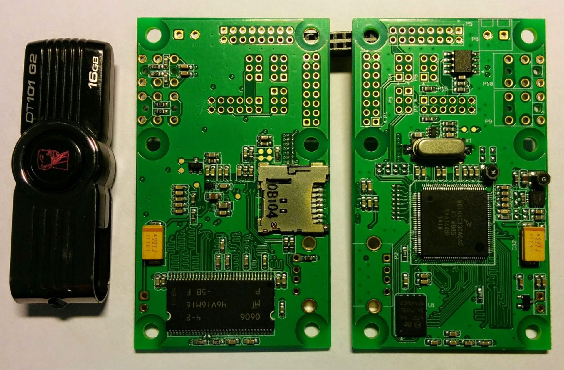
One-month later, soldered PCBs
had arrived and I could finally get down to business. (PCB production is a
difficult task, and it is a multiple-stage process. It requires many chemical
components, different materials such as fiberglass cloth, epoxy resin, and it's
quite hard to produce PCBs fast. However, this is only half of the production
process. The second stage is soldering. It‘s simpler task than PCB production,
but, in any case, it requires some time.)
SoC bringup
No doubts? Let's burn it out!
No smoke is the first sign of at least some early success. It’s good, not seeing any smoke. I connected a power-up button, and tried to run the device. By observing via oscilloscope, I saw a 24 MHz oscillation on the crystal oscillator. That’s not what I was hoping for, but was not the end of the world! A slightly imperfect waveform can always be defined by a passive oscilloscope probe with divider, etc.
SoC has an internal boot loader that determines startup rules by external jumpers or by OTP (one time programmable) bits. In addition, the bootloader can control the USB bus. I can always change jumper configurations but OTP is OTP. By changing jumpers, I got the first bytes of data from the debug port!
Its means that the power subsystem could provide a correct power supply and the processor could start working. It was possible to go forward! Some time later, I found the meaning of the debug messages in some unofficial documentation.
The author of this document referred to himself as "huashan" Well, okay.
For better flexibility, I would like to connect the board to a PC via USB. This would allow uploading software by one command. Let's give it a go! However, the connected device didn’t come to life. (And just sat here, like an unplugged refrigerator)
I didn’t see even one transaction via the USB bus and no oscillation on the crystal oscillator. Nothing happened.
I started looking for a mistake in my solution. For example, near the SoC I used an extra DC/DC regulator, with no load, but I connected it to the power supply. Via an oscilloscope, I saw 5 volts on the input, and 5 volts on the output. Here you are! A DC/DC regulator with no resistor in the feedback loop could break the circuit. (Looks like a joke: -Captain, Captain, the anchor has surfaced! -Hmm, that’s not a good sign...)
It was strange, but when I repaired it, my “hand-made” device was detected by the PC!
I checked the quality of the power supply before this workaround. It looked fine, with no noise, and with a value of 5.1 volts. However, the SoC in this case looked like a boss who makes his own decision. After repairing the DC/DC regulator, it could work in the correct way. It worked without a load, and with no interferences. Nice!
The next step was configuring the DDR memory. I started to search for a memory configuration, and some time later stitched together a pack of "bootlets", the system and some additional software. Tiny sources which are able to initialize a PMU (power management unit) and a DDR controller. It looks ideal - small and trivial, without complicated parts, and it can actually work!
Extra software allows us to upload these "bootlets" into the SoC and run them.
It looks so difficult because after power-up of the SoC, the processor doesn't know anything about the external memory. This means that the processor has no space for future work. (These initialization steps apply to any device like a PC or smart phone.) It looks like a chain of simple steps where each step is independent, but together they’re able to provide a working environment.
When I finished compilation of the sources, and uploading them into the processor, I saw this log in the debug console. It was amazing! Power distribution system was finally alive!
PowerPrep start initialize power…
Battery Voltage = 0.65V
No battery or bad battery detected!!! Disabling battery voltage measurements.
EMI_CTRL 0x1C084040
FRAC 0x92926152
power 0x00820710
Frac 0x92926152
start change cpu freq
hbus 0x00000003
cpu 0x00010002
I looked at the memory initialization source code. When I edited it in accordance with the installed memory chip, I uploaded it to the processor again. And it looked really awesome! It meant that the memory chip was connected correctly, without any terrible mistakes, and it was possible to upload something intelligent.
PowerPrep start initialize power…
Battery Voltage = 1.74V
No battery or bad battery detected!!!.Disabling battery voltage measurements.
EMI_CTRL 0x1C084040
FRAC 0x92926152
power 0x00820710
Frac 0x92926152
start change cpu freq
hbus 0x00000003
cpu 0x00010002
start memory test, at 0x40000000
end memory test, at 0x41FFFFFC
U-Boot
More intelligent - for example, is U-Boot. I know this system, and I think it looks good and it’s functional. This system allows users to work with different peripheral devices such as USB/SD/MMC storage and Ethernet networks, and able to download different executable files from FAT/etx2 partitions, and, it's amazing that this system is even able to blink an LED! :)
For these reasons, I chose this system. I downloaded the latest version from the official site, chose the latest configuration, compiled it, and uploaded it again.
PowerPrep start initialize power…
Battery Voltage = 1.74V
No battery or bad battery detected!!! Disabling battery voltage measurements.
EMI_CTRL 0x1C084040
FRAC 0x92926152
power 0x00820710
Frac 0x92926152
start change cpu freq
hbus 0x00000003
cpu 0x00010002
start memory test, at 0x40000000
end memory test, at 0x41FFFFFC

U-Boot 2015.04-rc3-00209-ga74ef40 (Mar 16 2015 — 12:47:34)

CPU: Freescale i.MX23 rev1.4 at 227 MHz
BOOT: USB
DRAM: 32 MiB
MMC: MXS MMC: 0
MMC0: Bus busy timeout!
MMC0: Bus busy timeout!
MMC0: Bus busy timeout!
MMC0: Bus busy timeout!
Card did not respond to voltage select!
MMC init failed
Using default environment

In: serial
Out: serial
Err: serial
Net: Net Initialization Skipped
No ethernet found.
Hit any key to stop autoboot: 0
=>
And it ran! Fine, SoC could run, but at this moment it was running via wires. A more correct way is booting via micro SD card. Ok, after editing the jumper configuration, I tried to run the system from the memory card. However, when I tried to do that I saw one error code, and saw another error when I tried to run it without a card. What a twist!
Micro SD card
When I looked for a solution, I found a Russian-language forum with more than 380 posts of discussions about this SoC. I'm afraid that those gentlemen still live with nightmares about this SoC. After exploration, I came to the conclusion that booting from a micro SD card is needed to write to OTP memory, in particularly to change the SD MBR Boot[3] option, and choose NO_GATE in register SD_REG, because my board’s micro SD card holder has no power control option. It looks like an uncomfortable truth. It means that it is impossible to make a "master-SD-card" that can be used for factory flashing. Anyway, the SoC must be connected to a PC for writing this setting. This nuance must be remembered in the future for more accurate SoC selection. So, the current design is not applicable for serious investigations and this situation isn’t mission critical. When I downloaded and installed the "BitBurner" application and adjusted the OTP bits, I saw a reset taking place happening. Damn it!PowerPrep start initialize power… Battery Voltage = 3.75V Boot from battery. 5v input not detected PowerPrep start initialize power… Battery Voltage = 3.75V Boot from battery. 5v input not detected PowerPrep start initialize power… Battery Voltage = 3.75V Boot from battery. 5v input not detected ...
By adding extra debug messages in the source code, I found the problem:
PowerPrep start initialize power…
Battery Voltage = 3.75V
Boot from battery. 5v input not detected
Try poweron_pll
Try turnon_mem_rail
The system halted when it tried to power-up the DDR memory power rail. Hmmmmm... Somewhere, a long time ago I saw something like this. How was the system working before? In any case, this problem must be solved.
Around the DDR memory chip, I placed eight decoupling capacitors, 100nF each. It is recommended by the reference design for memory chip documentation.
However, the power source for memory is integrated into the SoC, and I departed from the recommendations (and it has different recommendations). I placed two extra capacitors, 10uF each. But by recommendations, here must be placed one, with 1uF capacitance. So, destruction is always simpler than construction. I removed one extra capacitor, tried again, and the system was running! You can see this capacitor in the first photo. It’s partially soldered, and it is dirty.
PowerPrep start initialize power…
Battery Voltage = 3.75V
Boot from battery. 5v input not detected
Try poweron_pll
Try turnon_mem_rail
Try init_clock
EMI_CTRL 0x1C084040
FRAC 0x92926192
Try init_ddr_mt46v32m16_133Mhz
power 0x00820710
Frac 0x92926192
start change cpu freq
hbus 0x00000003
cpu 0x00010001

Net: Net Initialization Skipped
No ethernet found.
initcall: 3e0a2e5c (relocated to 40005e5c)
Initial value for argc=3
Final value for argc=3
### main_loop entered: bootdelay=3

### main_loop: bootcmd=«mmc dev ${mmcdev}; if mmc rescan; then if run loadbootscript; then run bootscript; else if run loaduimage; then run mmcboot; else»
Hit any key to stop autoboot: 0
=>
=>
Ok, let’s try to run it by powering by an external 5V power source!
PowerPrep start initialize power…
Battery Voltage = 3.74V
5v source detected.Valid battery voltage detected.Booting from battery voltage source.
Mar 18 2015
07:59:13
Try poweron_pll
Try turnon_mem_rail
Try init_clock
EMI_CTRL 0x1C084040
FRAC 0x92926192
Try init_ddr_mt46v32m16_133Mhz
power 0x00820710
Frac 0x92926192
start change cpu freq
Hmm... In this case I saw the system halting. And behavior was unpredictable - sometimes the system was able to start, sometimes not; often it happened when the system was powered by the battery, sometimes when powered by an external 5V power source.
When I disabled clock switching, and left the core at 24 MHz, the system could start. Ok. However, the core was unable to run at 454 MHz. Fine, by adjusting the PLL settings I set the CPU speed to 320 MHz and observed stable performance. Some time later, I will investigate this question further, because I have some guess about this trouble.
Linux kernel
So, at this moment I have made a stable system, which is able to run U-Boot. The next step is building a Linux Kernel. When I downloaded the latest version from kernel.org and found the applicable default configuration, I compiled the kernel via these three simplest commands:
make ARCH=arm CROSS_COMPILE=${CC} mxs_defconfig
make ARCH=arm CROSS_COMPILE=${CC} menuconfig
make ARCH=arm CROSS_COMPILE=${CC} -j4 zImage modules
After compilation, I just copied it to the microSD card and tried to boot. "Kernel panic". I was happy to see it :) This was just fine, because the system has no root file system.Debian
I have used Debian. I like this system, because
it looks simple and reliable, just like a wooden stick J In this project, I could use a
"ready-to-use" distributive. With no questions, I unpacked the
archive on the micro SD card and tried again:
PowerPrep start initialize power…
Battery Voltage = 3.68V
Boot from battery. 5v input not detected
poweron_pll
turnon_mem_rail
init_clock
EMI_CTRL 0x1C084040
FRAC 0x92925E92
init_ddr_mt46v16m16_96Mhz
power 0x00820710
Frac 0x92925E92
start change cpu freq
Try now
hbus 0x00000003
cpu 0x00010001

U-Boot 2015.04-rc3-00209-ga74ef40-dirty (Mar 18 2015 — 14:26:18)

CPU: Freescale i.MX23 rev1.4 at 320 MHz
BOOT: USB
DRAM: 32 MiB
MMC: MXS MMC: 0
In: serial
Out: serial
Err: serial
Net: Net Initialization Skipped
No ethernet found.
Hit any key to stop autoboot: 0
2650994 bytes read in 906 ms (2.8 MiB/s)
Kernel image @ 0x41000000 [ 0x000000 — 0x284e60 ]

Starting kernel…

Uncompressing Linux… done, booting the kernel.
[ 0.000000] Booting Linux on physical CPU 0x0
[ 0.000000] Linux version 3.19.2 (freeman@freeman-PC) (gcc version 4.9.2 20140904 (prerelease) (crosstool-NG linaro-1.13.1-4.9-2014.09 — Linaro GCC 4.5
[ 0.000000] CPU: ARM926EJ-S [41069265] revision 5 (ARMv5TEJ), cr=0005317f
[ 0.000000] CPU: VIVT data cache, VIVT instruction cache
[ 0.000000] Machine model: i.MX23 Olinuxino Low Cost Board
[ 0.000000] Memory policy: Data cache writeback
[ 0.000000] Built 1 zonelists in Zone order, mobility grouping on. Total pages: 8128
[ 0.000000] Kernel command line: console=ttyAMA0,115200 root=/dev/mmcblk0p3 rw rootwait
[ 0.000000] PID hash table entries: 128 (order: -3, 512 bytes)
[ 0.000000] Dentry cache hash table entries: 4096 (order: 2, 16384 bytes)
[ 0.000000] Inode-cache hash table entries: 2048 (order: 1, 8192 bytes)
[ 0.000000] Memory: 18972K/32768K available (3475K kernel code, 244K rwdata, 1372K rodata, 188K init, 8096K bss, 13796K reserved, 0K cma-reserved)
[ 0.000000] Virtual kernel memory layout:
[ 0.000000] vector: 0xffff0000 — 0xffff1000 ( 4 kB)
[ 0.000000] fixmap: 0xffc00000 — 0xfff00000 (3072 kB)
[ 0.000000] vmalloc: 0xc2800000 — 0xff000000 ( 968 MB)
[ 0.000000] lowmem: 0xc0000000 — 0xc2000000 ( 32 MB)
[ 0.000000] modules: 0xbf000000 — 0xc0000000 ( 16 MB)
[ 0.000000] .text: 0xc0008000 — 0xc04c42ac (4849 kB)
[ 0.000000] .init: 0xc04c5000 — 0xc04f4000 ( 188 kB)
[ 0.000000] .data: 0xc04f4000 — 0xc0531018 ( 245 kB)
[ 0.000000] .bss: 0xc0531018 — 0xc0d19264 (8097 kB)
[ 0.000000] SLUB: HWalign=32, Order=0-3, MinObjects=0, CPUs=1, Nodes=1
[ 0.000000] NR_IRQS:16 nr_irqs:16 16
[ 0.000000] sched_clock: 32 bits at 100 Hz, resolution 10000000ns, wraps every 21474836480000000ns
[ 0.000000] Console: colour dummy device 80x30
[ 0.000000] Lock dependency validator: Copyright © 2006 Red Hat, Inc., Ingo Molnar
[ 0.000000]… MAX_LOCKDEP_SUBCLASSES: 8
[ 0.000000]… MAX_LOCK_DEPTH: 48
[ 0.000000]… MAX_LOCKDEP_KEYS: 8191
[ 0.000000]… CLASSHASH_SIZE: 4096
[ 0.000000]… MAX_LOCKDEP_ENTRIES: 32768
[ 0.000000]… MAX_LOCKDEP_CHAINS: 65536
[ 0.000000]… CHAINHASH_SIZE: 32768
[ 0.000000] memory used by lock dependency info: 5167 kB
[ 0.000000] per task-struct memory footprint: 1152 bytes
[ 0.060000] Calibrating delay loop… 159.12 BogoMIPS (lpj=795648)
[ 0.070000] pid_max: default: 32768 minimum: 301
[ 0.070000] Mount-cache hash table entries: 1024 (order: 0, 4096 bytes)
[ 0.070000] Mountpoint-cache hash table entries: 1024 (order: 0, 4096 bytes)
[ 0.080000] CPU: Testing write buffer coherency: ok
[ 0.080000] Setting up static identity map for 0x40353070 — 0x403530c8
[ 0.110000] devtmpfs: initialized
[ 0.130000] pinctrl core: initialized pinctrl subsystem
[ 0.180000] DMA: preallocated 256 KiB pool for atomic coherent allocations
[ 0.290000] Serial: AMBA PL011 UART driver
[ 0.290000] 80070000.serial: ttyAMA0 at MMIO 0x80070000 (irq = 17, base_baud = 0) is a PL011 rev2
[ 0.480000] console [ttyAMA0] enabled
[ 0.560000] mxs-dma 80004000.dma-apbh: initialized
[ 0.590000] mxs-dma 80024000.dma-apbx: initialized
[ 0.600000] SCSI subsystem initialized
[ 0.610000] pps_core: LinuxPPS API ver. 1 registered
[ 0.610000] pps_core: Software ver. 5.3.6 — Copyright 2005-2007 Rodolfo Giometti
[ 0.620000] Switched to clocksource mxs_timer
[ 1.130000] futex hash table entries: 256 (order: 1, 11264 bytes)
[ 1.290000] jffs2: version 2.2. (NAND) © 2001-2006 Red Hat, Inc.
[ 1.320000] Block layer SCSI generic (bsg) driver version 0.4 loaded (major 250)
[ 1.330000] io scheduler noop registered (default)
[ 1.340000] of_dma_request_slave_channel: dma-names property of node '/apb@80000000/apbx@80040000/serial@80070000' missing or empty
[ 1.360000] uart-pl011 80070000.serial: no DMA platform data
[ 1.360000] 8006c000.serial: ttyAPP0 at MMIO 0x8006c000 (irq = 146, base_baud = 1500000) is a 8006c000.serial
[ 1.380000] mxs-auart 8006c000.serial: Found APPUART 3.0.0
[ 1.410000] mousedev: PS/2 mouse device common for all mice
[ 1.430000] stmp3xxx-rtc 8005c000.rtc: rtc core: registered 8005c000.rtc as rtc0
[ 1.440000] i2c /dev entries driver
[ 1.450000] stmp3xxx_rtc_wdt stmp3xxx_rtc_wdt: initialized watchdog with heartbeat 19s
[ 1.460000] softdog: Software Watchdog Timer: 0.08 initialized. soft_noboot=0 soft_margin=60 sec soft_panic=0 (nowayout=0)
[ 1.470000] Driver 'mmcblk' needs updating — please use bus_type methods
[ 1.480000] 80010000.ssp supply vmmc not found, using dummy regulator
[ 1.540000] mxs-mmc 80010000.ssp: initialized
[ 1.630000] mmc0: host does not support reading read-only switch, assuming write-enable
[ 1.640000] stmp3xxx-rtc 8005c000.rtc: setting system clock to 1970-01-01 00:27:21 UTC (1641)
[ 1.660000] mmc0: new high speed SD card at address e624
[ 1.680000] mmcblk0: mmc0:e624 SU02G 1.84 GiB
[ 1.730000] mmcblk0: p1 p2 p3
[ 1.740000] usb0_vbus: disabling
[ 1.780000] EXT3-fs (mmcblk0p3): error: couldn't mount because of unsupported optional features (240)
[ 1.800000] EXT2-fs (mmcblk0p3): error: couldn't mount because of unsupported optional features (240)
[ 1.870000] EXT4-fs (mmcblk0p3): mounted filesystem with ordered data mode. Opts: (null)
[ 1.880000] VFS: Mounted root (ext4 filesystem) on device 179:3.
[ 1.910000] devtmpfs: mounted
[ 1.920000] Freeing unused kernel memory: 188K (c04c5000 — c04f4000)
INIT: version 2.88 booting
Using makefile-style concurrent boot in runlevel S.
Starting the hotplug events dispatcher: udevdudevd[78]: error getting socket: Function not implemented
error initializing control socketudevd[78]: error initializing udevd socket failed!
Setting the system clock.
Activating swap...done.
[ 6.410000] EXT4-fs (mmcblk0p3): re-mounted. Opts: (null)
Checking root file system...fsck from util-linux-ng 2.17.2
rootfs: clean, 10152/115920 files, 89453/462839 blocks done.
[ 6.870000] EXT4-fs (mmcblk0p3): re-mounted. Opts: (null)
Setting the system clock.
Cleaning up ifupdown…
Setting up networking…
Loading kernel modules...done.
Activating lvm and md swap...done.
Mounting local filesystems...done.
Activating swapfile swap...done.
Cleaning up temporary files…
Setting kernel variables ...done.
INIT: Entering runlevel: 2
Using makefile-style concurrent boot in runlevel 2.
Starting NTP server: ntpd.
Starting OpenBSD Secure Shell server: sshd.

Debian GNU/Linux 6.0 debian ttyAMA0

debian login: root
Password:
Last login: Thu Jan 1 02:00:41 EET 1970 on ttyAM0
Linux debian 3.19.2 #5 Thu Mar 19 10:58:08 EDT 2015 armv5tejl

The programs included with the Debian GNU/Linux system are free software;
the exact distribution terms for each program are described in the
individual files in /usr/share/doc/*/copyright.

Debian GNU/Linux comes with ABSOLUTELY NO WARRANTY, to the extent
permitted by applicable law.
root@debian:~#
root@debian:~# free
 	total 	used 	free 	shared 	buffers 	cached
Mem: 	19160 	18292 	868 	0 	1496 	9756
-/+ buffers/cache: 7040 12120
Swap: 0 0 0
root@debian:~#
root@debian:~# cat /proc/cpuinfo
processor: 0
model name: ARM926EJ-S rev 5 (v5l)
BogoMIPS: 159.12
Features: swp half fastmult edsp java
CPU implementer: 0x41
CPU architecture: 5TEJ
CPU variant: 0x0
CPU part: 0x926
CPU revision: 5

Hardware: Freescale MXS (Device Tree)
Revision: 0000
Serial: 0000000000000000
root@debian:~#
root@debian:~# df
Filesystem 1K-blocks Used Available Use% Mounted on
rootfs 1789440 295900 1384592 18% /
tmpfs 9580 0 9580 0% /lib/init/rw
udev 10240 0 10240 0% /dev
tmpfs 9580 0 9580 0% /dev/shm
tmpfs 9580 0 9580 0% /var/volatile
tmpfs 9580 0 9580 0% /media/ram
root@debian:~#
root@debian:~# mount
rootfs on / type auto (rw)
tmpfs on /lib/init/rw type tmpfs (rw,nosuid,mode=0755)
proc on /proc type proc (rw,noexec,nosuid,nodev)
sysfs on /sys type sysfs (rw,noexec,nosuid,nodev)
udev on /dev type tmpfs (rw,mode=0755)
tmpfs on /dev/shm type tmpfs (rw,nosuid,nodev)
devpts on /dev/pts type devpts (rw,noexec,nosuid,gid=5,mode=620)
tmpfs on /var/volatile type tmpfs (rw)
tmpfs on /media/ram type tmpfs (rw)
“Yeah, it looked awful!”
However, in any case, it is a single-board PC which uses the entire memory chip, able to run from a micro SD card. It was designed from scratch, on up to a working prototype. It had no serious mistakes, but did have some difficulties. So, I thought it was enough.
Conclusion
By the way, it's just the
beginning of life for this board. Because I need to explore the abilities of
this system, for example, audio and video outputs, determine stability and
measure power consumption.
It will be interesting to test
the system under different temperature conditions, or during resource-intensive
tasks, like video translation via secured Wi-Fi. However, I will cover this in
the next article.
In this article, I will make a
business offer to you!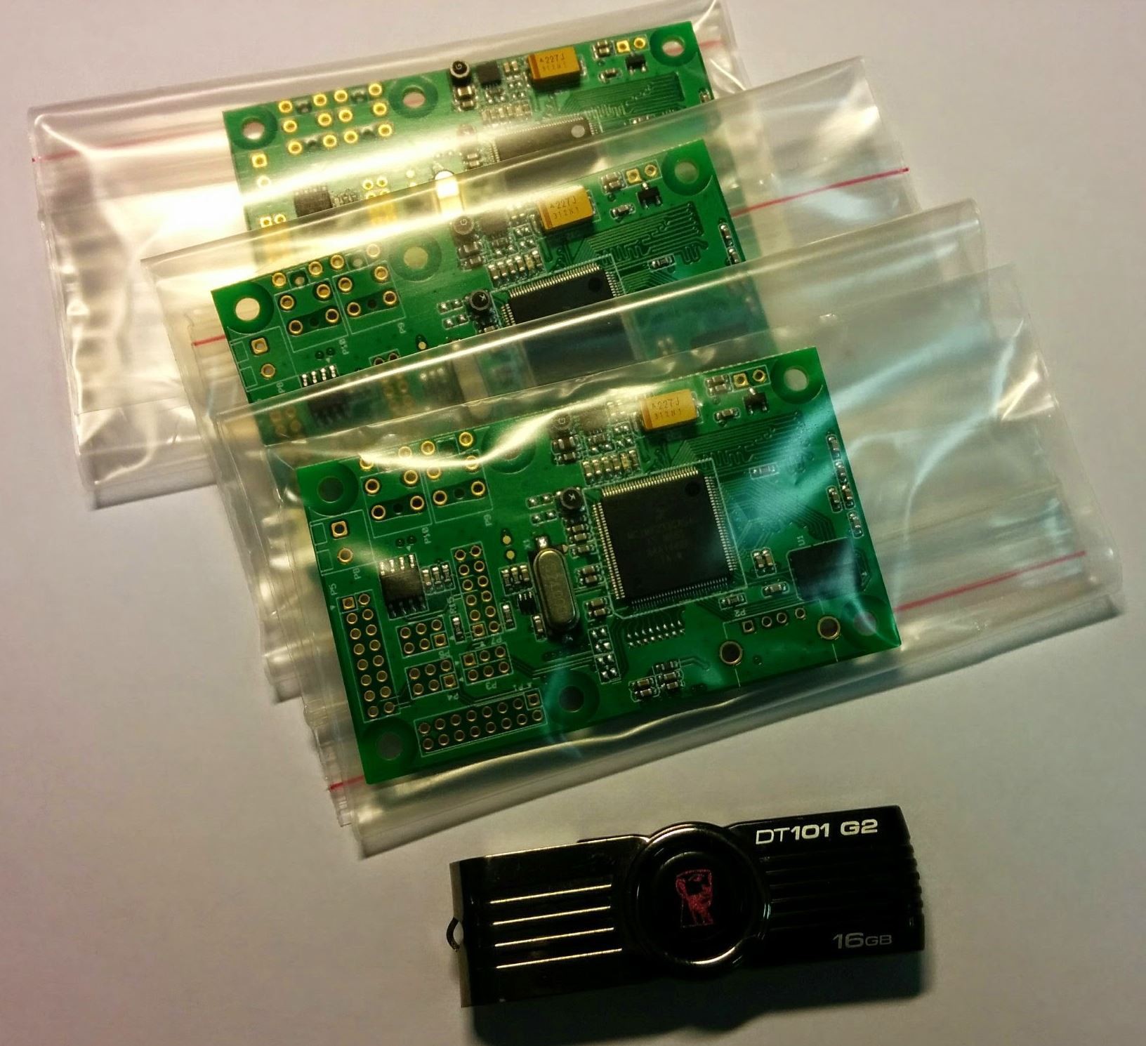
I have three working boards which I can give to anyone.
One tiny caveat: I will provide this board to anyone, as long as it’s for answering this one simple question: How is it possible to use this single-board PC? J
Authors with the best ideas will be awarded by these PCBs after 10 May 2016.
For me, this will be the best kind of feedback as it will provide me with a great quantity (and quality) of fuel for further development and refinement.
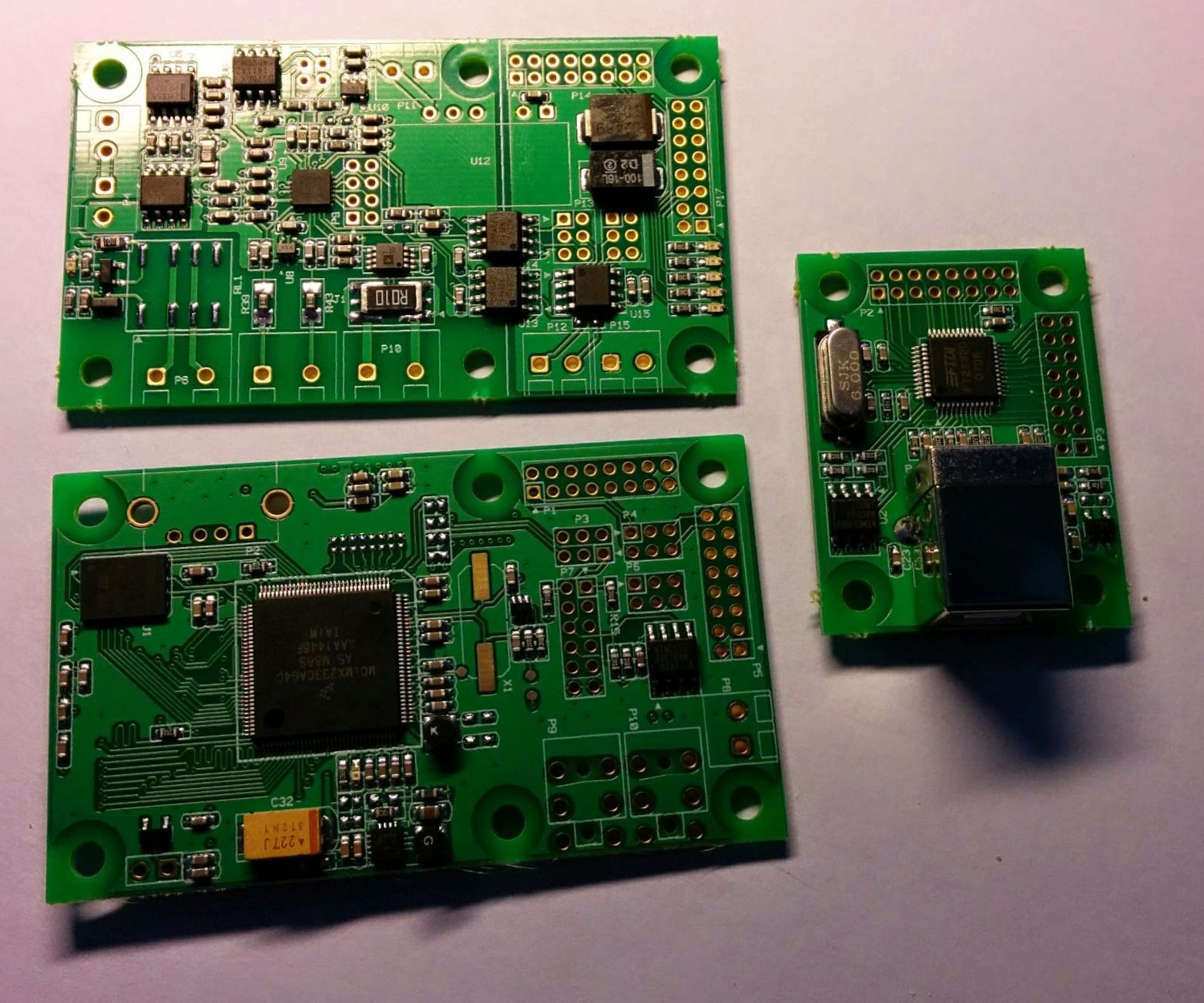
P.S.
Here is one more photo with extra boards. Is it looks interesting? :)
Regards, Andrew.