 jlbrian7
I am worried about this board because there are a couple of components I have never used before on it.
What I am wanting to do is bring out the remaining analog pins on the arduino to audio jacks that also supply 5v and gnd. From there you can plug anything you want into them. This board will have a whip on it with an audio plug on the end, and the audio jack here is so you can plug a current transformer into it, and the connector is to connect wires to the mains ( 1 board for each main line coming in) this will go to an AD629 (the part that worries me) . The other part that has me worried is the BAV99 that I replaced the diodes from my original board with.
The rocket fuel tank monitor that I used was using two of them as a bridge rectifier (that is my best guess because they were marked A7W and it would seem right, at least to me). That makes me think that they should be fine, but still a little worried about it. (Random tangent - I planned on ordering them anyway to rebuild the power circuit from the tank sensor reciever before I put my documentation online. If I get it right it looks like an easy compact way to power a circuit off of 120vac).
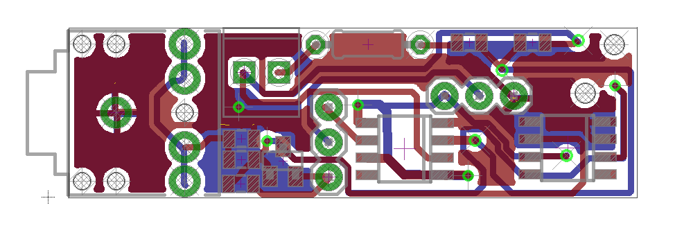
Here is a rough schematic of the board design...
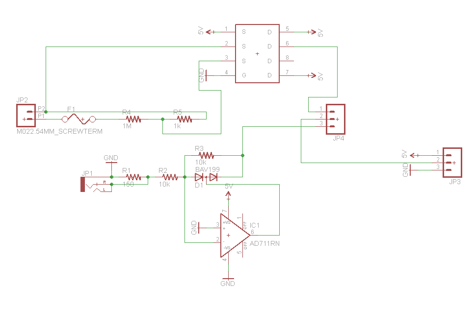
The part with the S's and D's is what I am using to represent the AD629 (the datasheet will have to suffice for now) until I create the part in Eagle, the part labeled BAV199 will be saved as BAV99, and the part labeled AD711RN is schematically correct but I am using TS1851IDT ( I can't pretend to know much about any of this, but I chose to keep this op amp on my bench because of the operating range).
If anyone has any advice before I build this I am all ears!
Discussions
Become a Hackaday.io Member
Create an account to leave a comment. Already have an account? Log In.
Are you sure? yes | no