Intro:
Sometimes when you start a project, you have a plan, and everything works out just as in the plan. Other times, you come up with quasi plan, encounter feature creep, run up against dead ends, almost loose interest, and then end up with something barely operational that looks very little like your original idea.The “Plan”
I acquired a significant stack of white LED boards. The first question I asked myself was what kind of project can I do with these boards? I should have stopped right there, it seems like when I do a project because I have a bunch of something, it doesn't seem to turn out well. One of the first things that came to mind was my guest bathroom. It has no windows and you have to walk in about 1 meter (3 feet) to get at the light switch. The light switch is not easily in view while walking in. It tends to confuse people and I have to turn on the light for them.
The original plan was to make a theater style light and sound system. One of the first “experiences” the system would do was a simulated rain storm. The LED boards would go above the crown molding and could act as general lighting and also lightning. There would be an ESP8266 above the crown molding and also a Raspberry Pi in the closet. The Pi would detect if any one was entering the bathroom, control the video projector, and the audio. Speakers in the closet would be attached to the Pi, a sub-woofer in the closet would act as thunder and a small, cheap projector would show simulated rain hitting the floor or the wall.
What was actually done:
The crown molding and other molding was put up in the bathroom. The LED lights were installed and a Passive Infrared sensor detects when someone enters the bathroom and turns off 3 minutes after the last motion is detected. The only thing the ESP8266 does is a 400mS ramp up time for the LED's and a 400mS ramp down when the LED's turn off. (An instant on and off would annoy me)
None of the raspberry pi things in the closet were started.
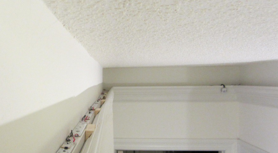
Figure: The LED boards on the crown molding
Controller board details:
The controller above the crown molding is a custom PCB from OSH Park. The PCB has a NodeMCU 0.9 (which is an ESP8266 based board), ten MOSFET controlled outputs, and runs at 24V. The 3.3V is generated by a small switcher that almost fits onto a TO-220 footprint. The NodeMCU has PWM outputs on some of the I/O pins. These PWM's are sync'd to each other other. From past experience, having the PWM switching at the same time can cause a massive amount of electrical noise. So, the 74VHC14's were added in to allow some delay to be added to the PWM outputs. Only 7 of the 10 possible outputs were used. I had assumed the NodeMCU 0.9 and NodeMCU 1.0 board had the same footprint, they do not. The version 1.0 is more narrow than version 0.9.
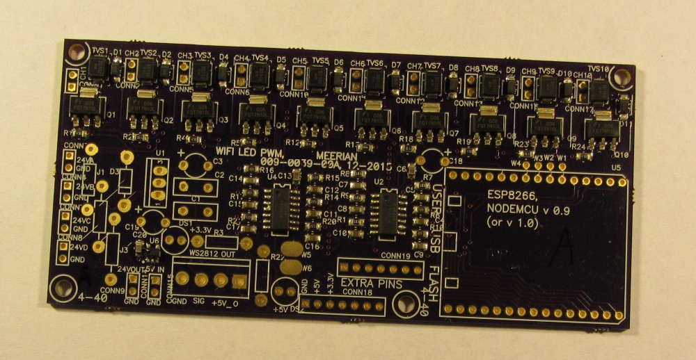
Figure: The wifi PWM controller after reflow (no through hole parts populated yet)
Two, 24V, 2.5A were used to power the controller above the crown molding. Space up there is rather limited. A single, large, 24V, 5A power supply would have been visible above the crown molding. The PCB was designed so that up to four, 24V power supplies could have been used. A WS2812 (addressable RGB LED, also called Neopixels) output was added but not used.
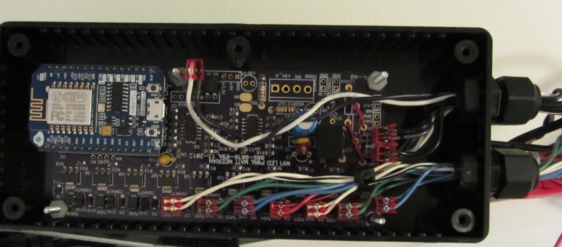
Figure: The built up controller with the NodeMCU 0.9 board installed
One of the biggest feature creep items on this project was the software. The ESP-8266 arduino add on was used as the development system. For various reasons, the ESP 8266 was running in stand alone access point mode. I was not able to get Over The Air (OTA) updates operational. The final software has 7 sliders on the browser that can control the intensity of each of the outputs. The PWM is running at 170 Hz.
The Passive Infra Red sensor:
This PIR sensor was ordered from eBay. It was mounted above the door going into the bathroom. I wanted the sensor to trip when someone walked in the bathroom, but not trigger when someone walked by the bathroom.
The sensor seemed to work rather well on the bench. But, when the 24V was ran over to the sensor and the output was ran back to the optocoupler (not shown in the schematic) on the controller board, the senor would lock on every couple of days. After some investigating, it was found the 24V had enough noise on it that it might be causing the PIR sensor. Since the current draw from the sensor is less than 2mA, a 4.7K resistor was put in series and several caps were used as a bypass filter. (low pass filter) This seemed to do the trick, the sensor has been operating correctly for about 3 weeks.
Carpentry:
The first step was to wire in a recessed outlet about 25cm (9 inches) down from the ceiling. I used an existing outlet in the bathroom and then fished wires up the inside of the wall.
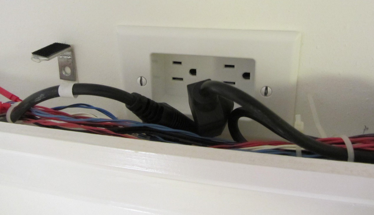
Figure: The recessed120VAC plug in with the LED boards over the outlet removed
The second step was to to select which pieces of molding would be used to create the cove lighting. The October 2015 issue of “Family Handyman” had a good article on installing cove lighting in a room. As usual with these types of articles, many of the small details are left out. The article had a time estimate of “one weekend”. That is laughable, it was much longer.
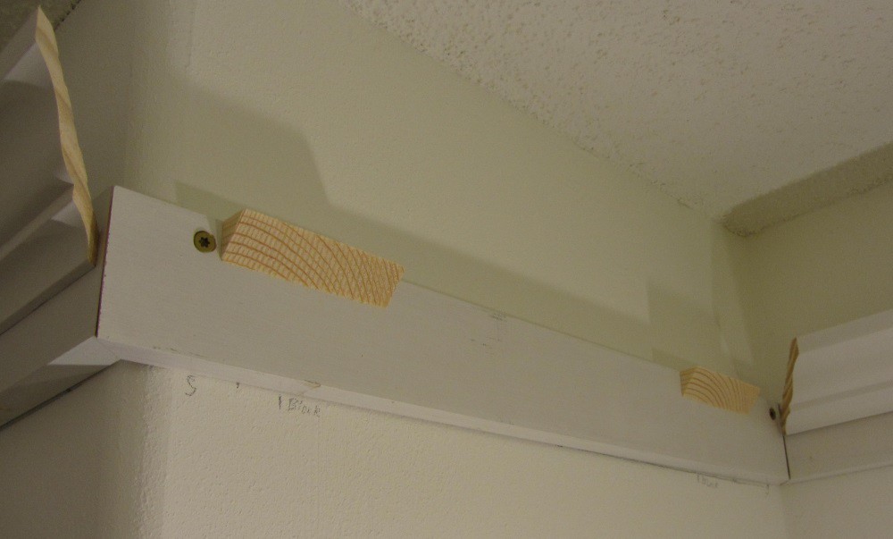
Figure: The 1x4 base is screwed to the wall and the 45 degree blocks are taped to the wall
From the above picture, you can kinda see how the crown molding was put up. The screws hold the 1x4's on to the wall. Then, crown molding is then put on by brad nails. I used a Ryobi One brad nailer. It worked a treat. Then, quarter round molding was put up on the bottom side of the 1x4's, again with the nailer. All of the visible parts were painted before I put them up.
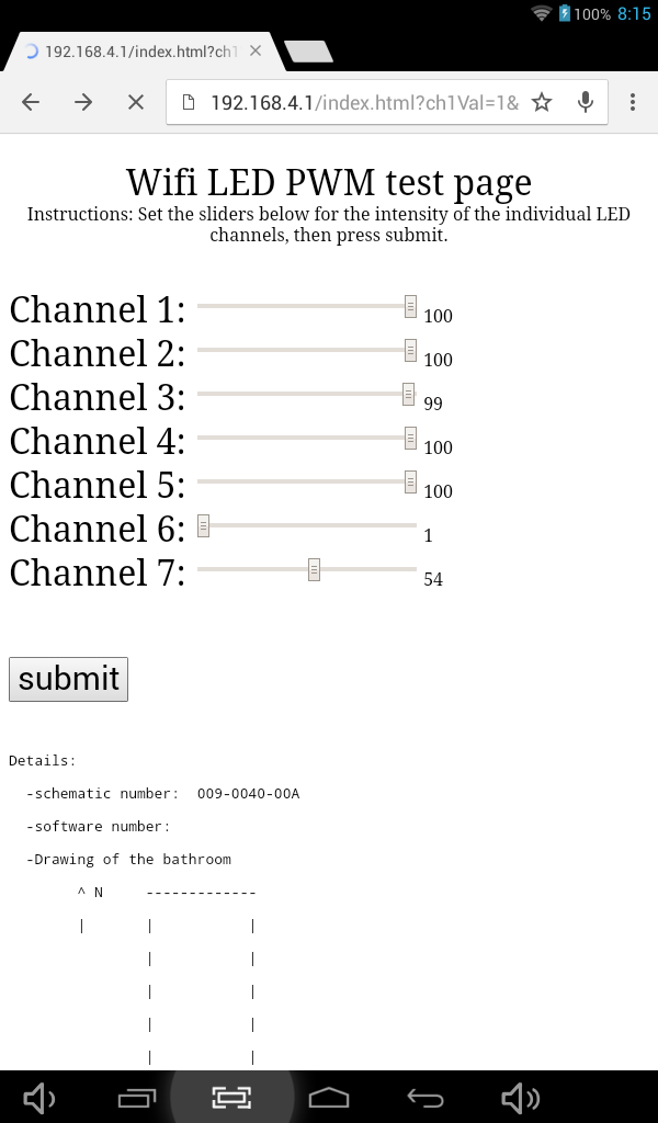
Figure: The sliders set the intensity for all 7 channels
Summary:
The functionality of this project turned out very basic. The electronics could probably be replaced with a couple of 555 timers.
The main downfall/time-waster of this project was the software for the ESP8266. The main part of the software has 7 sliders on the main page that allow the user to adjust the intensity of the LED strips. A number between 1 and 100 changes in real time for each slider. Putting up the crown molding was good, it's nice to spend a couple of hours working on something and then have made progress that is easily seen. So much of the time when working on the PC, you spend many hours working on software/schematic/etc and only sometimes you see progress.