 T. B. Trzepacz
The plan is to develop a printed circuit board with traces that act as contacts, and use those graphite impregnated silicone rubber cups to bridge the contacts and tell if the key has been pressed. I've disassembled a lot of toy keyboards, and that is how it is generally done.
Since we have the Othermill here at the Supplyframe Design Lab, it seems obvious to make the board here rather than to send out for it and wait a week. So I designed the circuit board in KiCAD, a program I wasn't really too familiar with yet.
In order to make the contacts on the PCB, I had to lay out copper traces on the PCB so that the rubber pads could bridge them easily. To do this, I made a custom footprint, as if I was going to mount a switch on the board, but I didn't put any holes for pins, just the pattern for the contact. This was a bit tricky, because KiCAD won't let you draw on the copper layer in a component except by placing a surface mount pad. Well, I thought that was kinda dumb, so I drew it on another layer and edited the text file to change it to the copper layer.
So, the first switch pad I designed looked like this:
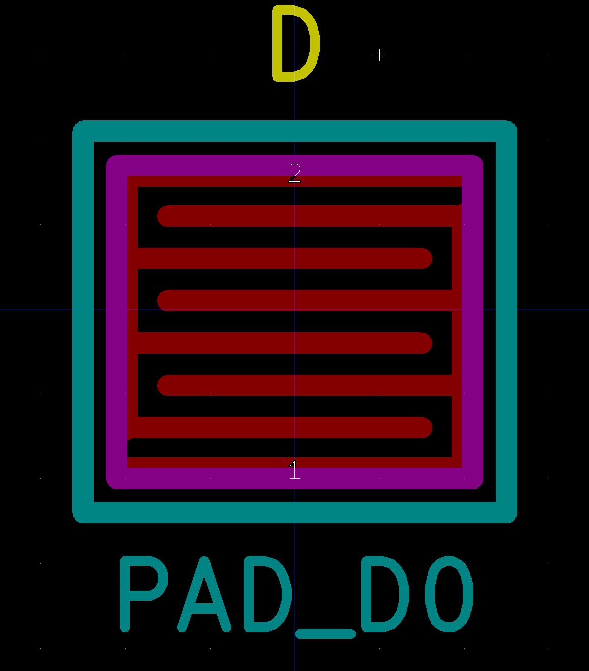
Looks nice enough, but there are barely 10 mils of spacing between the traces. While the Othermill can theoretically handle this, we had some trouble with it.

The 30 degree end mill that we used was supposed to be good for this, but somehow it didn't work out; all the traces vanished! So I adjusted the footprint for a wider spacing.
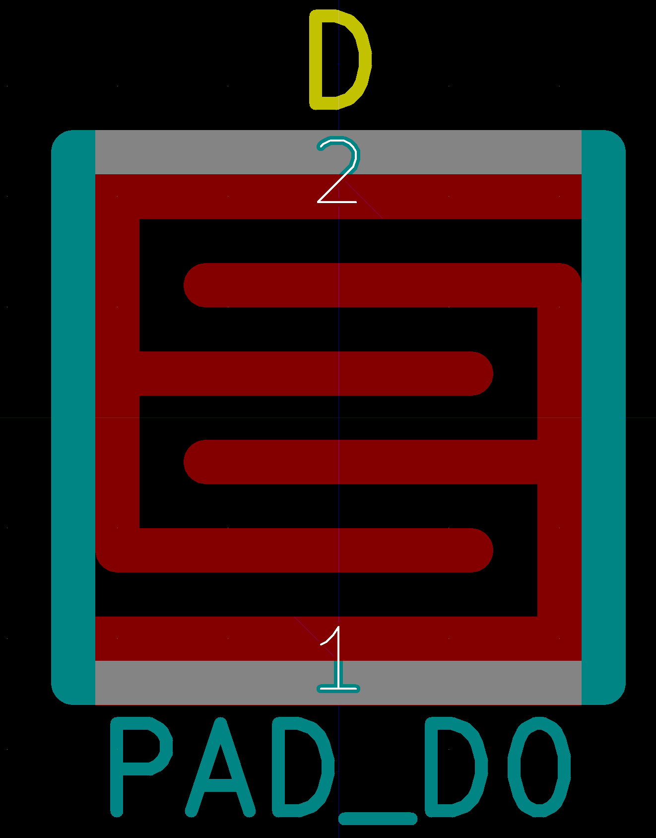
These have 20 mil traces and 20 mils between the traces, surely that will be good, right?
So we mill out another test. This seems better, right?

Still doesn't quite match what we drew, but maybe give it a go?
A schematic was made:
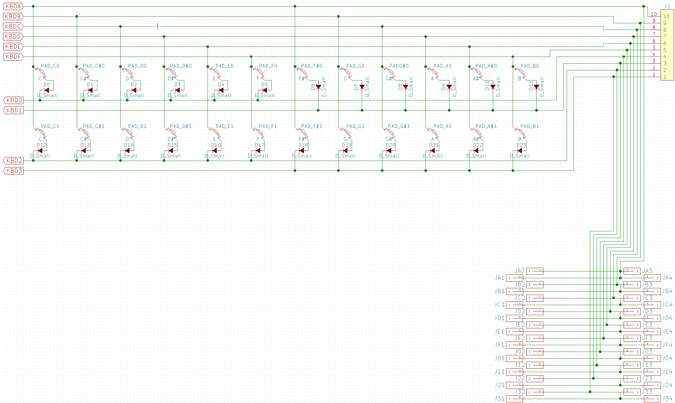
Diodes on each switch to prevent current from rushing up the wrong way and causing false triggers when chords are held.
The PCB had to be split into two parts because the Othermill will only do a 4" x 5" board.
Here is the front.


The 2nd board was missing part of a trace for some reason, so some rework was done:

And the boards were joined together with 0 ohm surface mount resistors:


As you can see, when the Othermill routs a circuit board, it doesn't rout all of the extra copper away, just the area around the trace. If you mill the board with a small bit, the area around the trace will be very thin, as it is here. This makes it VERY HARD to solder without bridging a connection! It took me a very long time to solder one of the vias (which are not plated through, because the Othermill has no way to do that) and I got more solder around the via than on it.


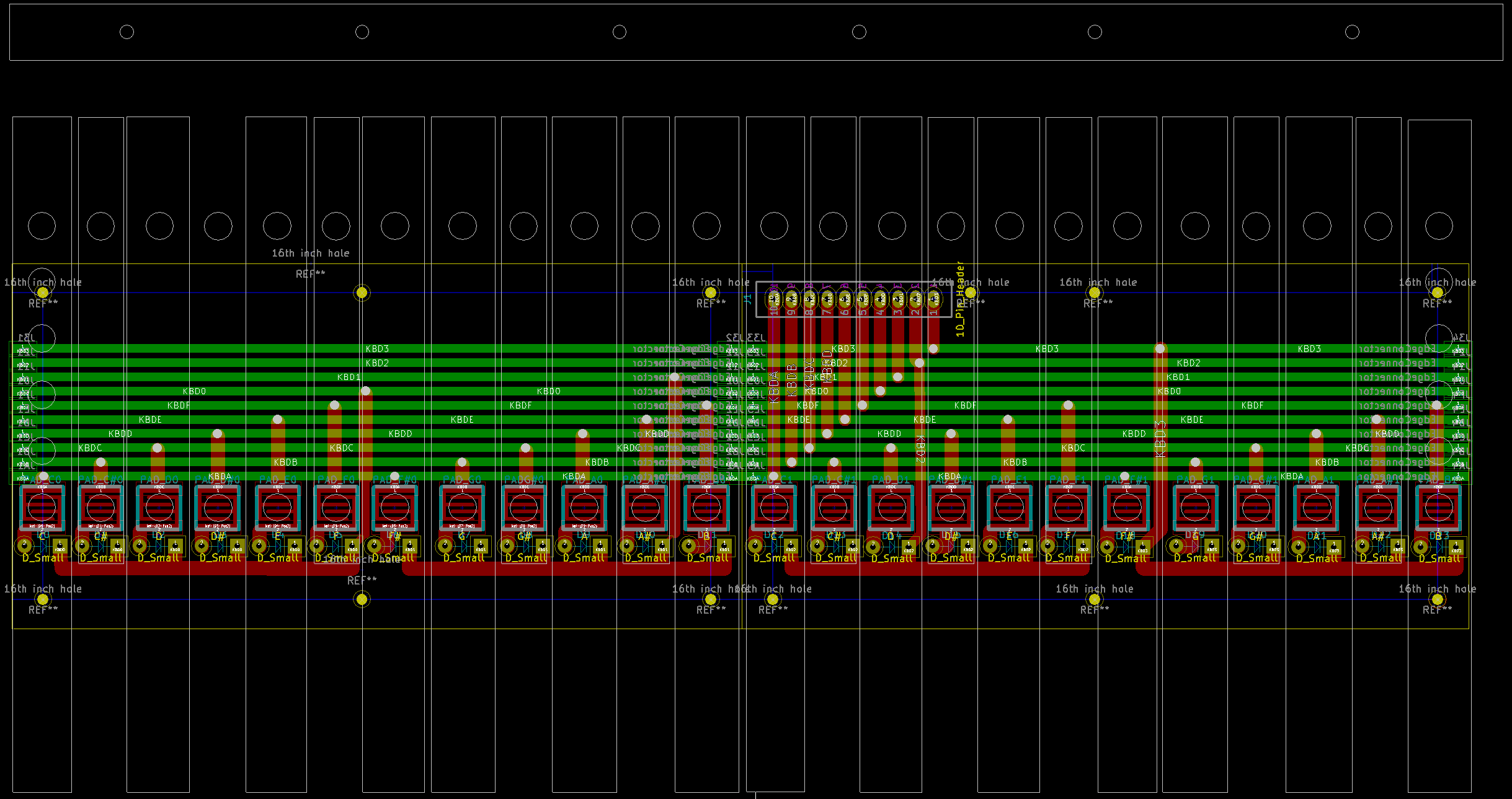 Here is the new board. Note that I imported a DXF of the key spacing to know how to line up the switch contact pads. The traces are a good 60 mils in most cases, and the vias and pads have large enough holes to work easily with a 1/32" flat end mill.
Meanwhile, Dan experimented with the Othermill and came up with a prescription that works:


And ended up with this:

So, back to the cutter...


And we're done! Let's try it!


Of course, this left the ends horribly burr'd, which made them much harder to put nuts on after. Cue the little wrench!


At this point, deficiencies in the design really started to show. The screws holding the acrylic that holds the pads in place, and even some of the acrylic itself, is blocking proper operation of the keyboard. So I cut some of the nubs off the bottom of the keys.

The nubs also don't *quite* line up with the rubber switch pads, but I only have the one set of keyboards printed, so I am determined to make it work. I need to measure precisely the position of each as it was glued. Doing that with a caliper would be fraught with error, so instead I just put it on the scanner and then traced it in Illustrator, making a DXF that could be imported into all of the CAD programs to make a new pad holder on the laser cutter.

Stay tuned for part 2: The revenge of the keyboard!
Discussions
Become a Hackaday.io Member
Create an account to leave a comment. Already have an account? Log In.