Close
0%
0%

Rocking the Horses

Learn how to operate your new CNC router by making a rocking horse, then learn a lot more by setting up for mass production.

Similar projects worth following
I'm entering this in Hackaday's Anything Goes competition.
The "problem" is that while cheap CNC routers are almost as available as 3d printers, the knowledge barrier to entry is significant.
This project aims to solve that by creating a useful entry project that exposes the machinist to increasing levels of complexity in manufacturing a fun and classic toy.
This work will be licensed CC BY-SA.

This project was done in 2 phases:

Phase 1 (complete):
Create Onshape model of rocking horse from free plans.
Write the Gcode for each piece by hand.
Cut each piece individually.
Give to daughter for Christmas!

Phase 2 (in-work, *complete):
*Adjust design based on prototype.
*Devise Manufacturing Method.
*Create fixturing scheme to enable cutting boards longer than the CNC table.
*Find easier way to create Gcode.
*Create a process document for instruction.
Use the process document and gcode files to create the first cutout.

History

Last year I sold my seldom used metal lathe and used the money to buy a Chinese CNC6040 on ebay. This is the first major project that I undertook, and I have learned a TON about the process of bringing a project from idea to finished item by way of CNC router. I am writing this partly in retrospect (Phase 1) and partly real-time (Phase 2) to hopefully help others in their quest to learn how to use a hobbiest level CNC router.

Present

If you are new to your CNC router coming from a start in 3d printing, you are probably like me with the first question being, where's the "slicer"???

You now need to come to grips with the fact that no one else's gcode will work on your machine. If you are going into this thinking you will just download other people's gcode and run it, similar to what you can get away with in 3d printing, STOP NOW. CNC routers are a level of complexity deeper than 3d printing. Seriously though, when you get a CNC router and are going the way of free software, there's not a one-stop software solution. You will need to LEARN GCODE. Really, it's not that hard and there are plenty of tutorials on the internet so I will forego any gcode training on this site unless I had a eureka moment that I want to tell you about. Lastly, you need to figure out a lot of stuff on your own. If you don't know how to do something, and you aren't getting good suggestions from the internet, just figure out your own way. It's part of the learning experience.

How to Get Started in CNC Routing

I firmly believe that the fastest way to learn is to do it yourself. In the first phase, I am going to do some of the the hard work, but encourage you to take on as much as possible. I'll lay out the process I went through step by step and publish the files to go with it. This project focuses on the easiest type of routing, which only involves cutting out a shape. The same principles could apply to a laser cutter, water jet, or plazma cutter, except that I'll focus on material removal with a router bit.

The Task

I am presenting the steps to cut out pieces that can be assembled into a Rocking Horse suitable for a toddler (1-3 yrs). The plans come from www.woodworkingdownunder.com and I used the"Rosie" plans found here, as my daughter was 16 months old when I started this.

The Software

www.Onshape.com is a free online modeling software. If you want to use my model or drawing files, you can register for an account and then use the link from the links section on this page to find my project in the public documents. Feel free to fork it.

For writing/editing gcode, I use windows notepad for quick edits, but prefer Notepad++ with the "G-Code (most CNC machines)" syntax language add on. (search the page for that text and use the link for the XML).

For converting drawings to gcode, first export the drawing from ONSHAPE as a PDF, then open in Inkscape, then export to DXF, then utilize dxf2gcode to write your base file. Knowing how to read the output and modify it will be key to fully taking control of your machine.

For Machine control I use Mach3 that came with my SeeMeCNC H1 3d printer. It appears to be an old version, but it came with the stepper driver controller. I keep looking at Linux CNC as an upgrade path. In general, everything I present will have application in whatever control software you use, as I will focus on the standard Gcodes, and program specific functions like setting up your machine to talk to the control software will not be covered here. The bottom line is, if your machine accepts gcode, this project should apply to you, but you will have to understand the limitations of your machine.

The Hardware

I purchased a 1.5KW CNC 6040 from the electronics bay, but they are widely available in the range of $1200 for the 3 axis models in multiple places on the internet. If you are just starting out, don't bother with the 4th axis, because you can use that money to buy the other stuff you will need - bits, collets, screws, wood.... and I highly recommend...

Read more »

SideA-1.ngc

Fixed radius comp - CW with retract

ngc - 18.02 kB - 06/20/2016 at 04:47

Download

SideA-2.ngc

Fixed radius comp - CW with retract

ngc - 18.86 kB - 06/20/2016 at 04:47

Download

Scarfboard.ngc

ngc - 618.00 bytes - 06/04/2016 at 21:12

Download

Phase 1 drawings.zip

x-zip-compressed - 202.61 kB - 05/30/2016 at 21:07

Download

SideB-6.ngc

ngc - 10.82 kB - 05/30/2016 at 21:03

Download

View all 13 files

  • 2 × 1 x 12 "Common Board" 4 ft long pine board from Home Depot, the actual physical dimensions are .7" x 11.75" x 48"
  • 1 × Box of Screws Wood screws, your choice
  • 1 × Wood Glue Pick your poison
  • 1 × Empty cartridges with 9mm class rim size .38spl, and .223 were used here
  • 1 × Felt Multiple colors: Black, Red, White

View all 6 components

  • Know G-code, Fix Cam Package Errors

    Josh06/09/2016 at 17:55 0 comments

    New files for SideA-1.ngc and SideA-2.ngc are posted in conjunction with the following.

    So it has taken me a few weeks to get some time to look into the issue with the rockers and cutter compensation. I assumed that it was an issue with how Mach 3 interpolates between changes in cutter compensation, but it may be simpler than that.

    Dxf2gcode is the software that I used to create the gcode. When the problem occured, I looked at the code and saw that it was applying what appeared to be the proper compensation in the code and Mach 3 printed what appeared to be the correct cutter compensation path. What I didn't do was take 30 seconds an confirm the actual Gcode command issued.

    Assuming I needed new lead-ins each time I changed direction, I began to manually add a small offset cut at the end of each path prior to the direction change to provide a new lead in. That's when I noticed that the code was calling G40 at each direction change rather than the required G41 (LH) or G42 (RH). G40 SHUTS COMPENSATION OFF. It wasn't apparent on the Mach3 sim because the first cut produced the proper compensated path, so without rotating the view, each subsequent pass appeared to follow the last.

    So only the first cut was applying compensation. Each cut depth after was just cutting on the uncompensated line.

    I have replaced the G40 commands with the correct G41 and G42 commands, and I'll be giving it a shot again as soon as I can!

    I'll submit a bug report to the Dxf2gcode project.

    (edit: after exploring some settings)

    It appears that there is an option to turn off compensation between cuts. When this option is enabled, it successfully applies the correct compensation on the next pass. So I will now utilize this option, even though I think it is still erroneous without that option.

  • Phase 2 + 1 Files Uploaded!

    Josh05/30/2016 at 21:15 0 comments

    All of the files for Phase 2 are now available, including the SVG, DXF, and G-code. All files CC BY-SA 4.0. These files are untested at the moment, and the toolpath problem on the rockers still has not been corrected, although I believe it is a Mach3 issue. I will update these when I get a chance.

    All drawings needed for Phase 1 are now uploaded (these are the same as you would find in ONSHAPE, so now you don't need an ONSHAPE account to get the drawings.)

    I will do a write up later for the Phase 1 instructions, but as of now, all files are available for those who wish to use them, and for inclusion in the Hackaday Anything Goes competition.

    Feel free to ask any questions! The point of this project is to help those in need of some starter CNC info!

  • Files for Phase 2

    Josh05/27/2016 at 18:55 0 comments

    I am working on uploading files for Phase 2. Please check the files section for updates. I will follow up later with files for Phase 1. As I will be out of town for the weekend, I'm not sure if I will get all files posted prior to the deadline, but we shall see.

  • Phase 2: Failure on Multiple Levels

    Josh05/25/2016 at 13:56 0 comments

    There were 3 main failures that occurred last night when trying to run the procedure.

    1. Cutter compensation did not function properly
    2. Manually jogged into a hard stop
    3. Wood size was different than I thought


    This video shows a time lapse of the first try of producing the rocking horse cutouts:

    Read more »

  • Phase 1 Recap: Design Iteration

    Josh05/19/2016 at 17:09 0 comments

    After building the horse from all of the parts, I ran into the following issues, and determined fixes for the next time:

    1. Rockers are too short! My daughter promptly flipped off the back on her first ride, and has subsequently gone over the front a few times as well. Easy fix: longer rockers! Keep the Rider's CG inside the "pie" shaped by the rocker radius and length.
    2. Mane. The mane was not thought out ahead of time, and I had to dremmel a slot in the back of the neck to glue in a bunch of yarn. The next horse will just have a wavy back that can be painted.
    3. Mouth Features. The mouth didn't really look like a mouth until we added felt features to accentuate the neck line. The neck and mouth should be redone to make it easier to envision, even before painting/felting.
    4. Streamlined Gcode. Now that I know how to write it, I can explore programs that will turn my drawings directly into gcode, and then modify the output directly if needed.

    Next up: On to Phase 2!

  • Phase 1 Recap: Feeds and Speeds

    Josh05/19/2016 at 16:13 0 comments

    (edited to bring more accurate feed/speed guidance)

    It seems that there are quite a few different ways to calculate feeds and speeds, but I'll give you my take.

    Feeds - How fast you cut (how fast tool travels when cutting), in units/minute.

    Speeds - Rate at which a rotating tool spins

    Chip Load - the size of the "bite" that the tool takes on every cut.

    I tried to do some research to find out some other people's ideal settings for cutting wood, but I never found any and I just decided to give it a go.

    My Experience

    My tool starting out is a 1/4" diameter, 2-flute straight cutter. This means it has 2 cutting surfaces and no spiral. I didn't choose it for any reason other than I had it in a box that I kept when I sold the lathe and it was still packed new in wax. I started out just setting my spindle to the max speed (25,000 rpm) and cutting slowly (20 in/min). This worked just fine, but I didn't get wood chips, I got wood dust. As I cut parts, I slowly increased the speed.

    What I found was that somewhere around 70 in/min the dust started to transition into fine chips of wood. Chips would be an over statement, as they were more like delicate shavings. This makes sense, because the calculations really aren't that hard. Chip size = Feed/(speed*flutes). So my chip size is 70/(25,000*2) = 0.0014". This is about 1/3 the thickness of a sheet of printer paper.

    I eventually pushed the machine up to 100 inch/min and it had no problems cutting through at a depth of 1/4". Redoing the chip calculation, I should be getting 100/(25,000*2) = 0.002" thick chips. These were nice chips that the vacuum easily removed and there was little dust formed in the process. I decided that I will target a 0.002" chip thickness for this tool moving forward.

    Method to Figure out Feeds/Speeds

    So to answer the great question: where do I set my feeds and speeds? High spindle speed and low feed rate sounds like a logical place to start, but DON'T DO IT! You'll set yourself up to burn up your tool and your work. The problem is that even though our tools appear to be "sharp" when you look at them under a microscope, the "sharp" edge has a radius. <This article> does a great job of explaining, but basically the radius of that edge seems to be on the order of .0001" and if your chip load gets close to this number, your cutter doesn't cut, it "pushes" or rubs the material. I'd suggest shooting for 10X this and aiming for a .001" chip load.

    Here is a good method for wood:

    1. Calculate a starting feed rate such that you will have a chip load of about .001" The formula is Feed = chip load * RPM * #flutes.
    2. If your machine can't travel that fast, then calculate your spindle speed RPM based on your max feed rate: Speed = Feed/(chip load * #flutes).
    3. If your tool is excessively heating your work piece, burning or melting it, Either SPEED UP your FEED rate, or REDUCE your spindle RPM. Chips carry most of the heat away from the work, so speeding up the feed rate makes more chips to cool the tool, while reducing the RPM produces less friction and bigger chips at the same feed. This also means you probably aren't hitting the calculated values for either feed or speed for the target chip load.
    4. If you are getting rough edges, or can see a significant line between each cut layer, you are probably getting excessive tool deflection. Reduce depth of cut, take more passes to cut your part. You can also reduce your chip load, but this has a side effect of causing more heat. I found many people said not to set depth of cut deeper than the cutter's diameter.
    5. If you are getting corners that are not well-defined, you may have a backlash or acceleration issue. Reduce your velocity slope (acceleration) so that your spindle head will slow down for changes in direction. Be wary that lower accelerations may cause your machine to fail to reach the specified feed rate in some areas with lots of direction changes. This means you should reduce your spindle speed to try to keep the chip load higher.
    6. Listen to your...
    Read more »

  • Phase 1 Recap: Making a Part Larger Than Your Table

    Josh05/19/2016 at 13:28 0 comments

    This is a short log detailing my method to machine the rockers, which were much longer than the router table.

    Continuity

    The biggest issue I faced with my machine is no Homing. So when I wanted to make a part longer than my router table, I had to ensure that the machine maintained its coordinates and didn't reset the home position during the whole process.

    Fixturing - Index Holes

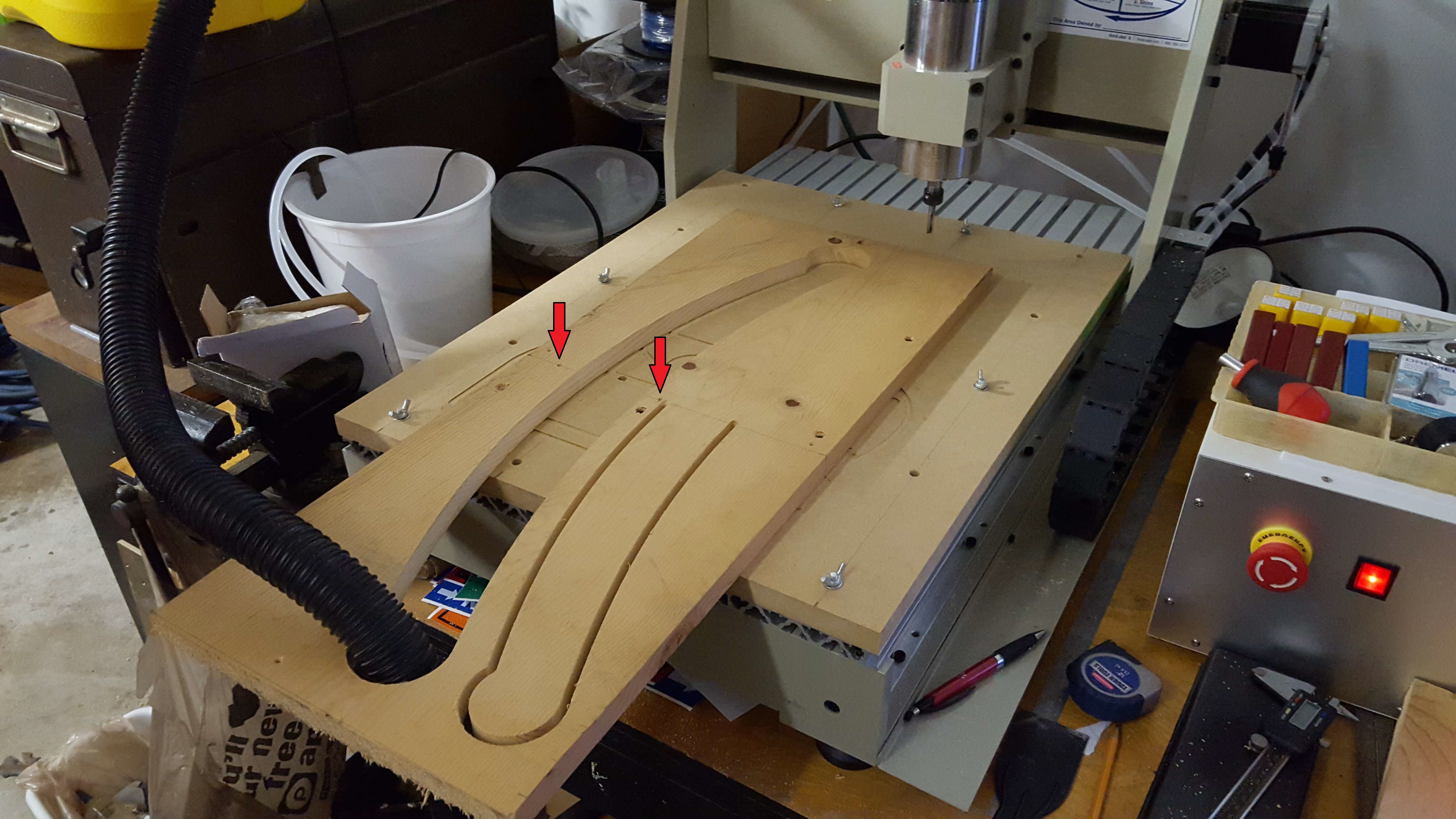
    Although the full rocker wouldn't fit on the table, half the rocker easily did. I wrote my gcode file to cut half of the rocker at the centerline, so that I could flip the piece end-over-end and cut the other half of the rocker. The only thing I needed was an accurate way to flip it. I did this by writing a second gcode file that first drilled two holes, one on either side of the centerline of the rocker, that went all the way through the stock and into the scarfboard. I then used dowel pins in the holes to align the stock when I flipped it. Since I was cutting exactly half of a rocker, I could use the same gcode file for each side. In the image below its hard, but you can see the 1/8" drill holes (red arrows) used for indexing the board when I flipped it.

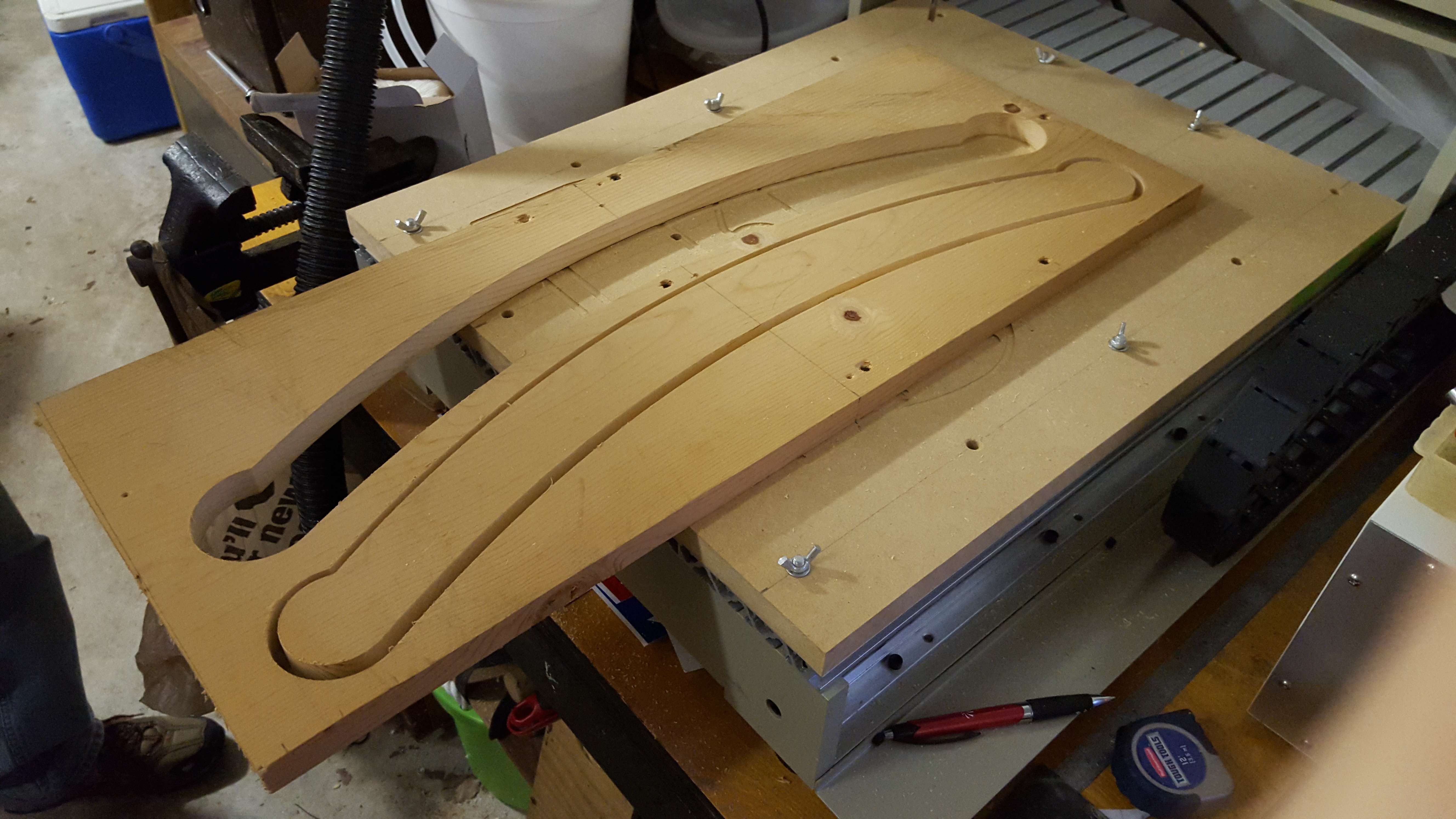
    And here is the final cut:

    Gcode Lessons

    Since the rocker is shaped using only circles, cutting half of the rocker only required 4 lines of gcode for the tool path: one for the bottom surface, one for the fillet between the bottom and the end, one for the end, and one for the top. Adding gcode for the plunges and I was able to write the gcode for this part manually in a few minutes. I did have a major problem when I first wrote this code, however. I hand coded it then ran it using Camotics free simulation software. It looked great! Then when I loaded it in Mach3, the tool path visualization was completely wrong. It took me some research to find that gcode specifies relative arc center points by default, separate from the absolute (G90)/relative(G91) coordinate move setting. I was using absolute coordinate moves (G90) but Mach3 thought I wanted relative arc centers, so it was putting the arc centers in the wrong location.

    I changed the gcode by putting in the relative center locations and everything worked great, then I discovered that I could have used G90.1 to switch to absolute IJK mode and not changed the gcode.

  • Phase 1 Recap: Learning CNC the Hard Way

    Josh05/18/2016 at 22:04 0 comments

    Exciting Beginings

    Last year I decided to sell my metal lathe, a 40" gap-bed behemoth, and use the money to buy a Chinese CNC6040 router. I had the lathe for a long time and rarely used it, so the swap made sense to me.

    Before I got my Chinese CNC6040 I had already made an attempt to build a 3d printer based on the SeeMeCNC H1. That printer sucked. I got it to print once, and it wasn't a very good print. I then spent about 4 years trying to tweak the printer to get it to print better before it started to fail all over the place. So when the CNC came in the door, the H1 got wholesale dumpped in a box on a shelf so that I could use the computer for the CNC.

    Prior to getting the CNC, I already had some experience with Mach3 and setting up the hardware, but to be honest, gcode was still almost black magic to me. I just knew that when I ran my slicer, it spit out hundreds of lines of gcode, and I had no interest in trying to peel back the layers of how it worked since the gcode files were never the problem.

    I was so excited to have my CNC that in the days leading up to its arrival, I began to realize that I needed a project to do when it arrived. I started searching for free software to help me out when I hit the first major road block: free CNC software SUCKS. I spent weeks trying to find, download and use software that could create gcode as easily as slicers create 3d prints. What I found was a bunch of software that was based on hacks that people had developed with little documentation (or documentation in foreign languages) and was only good for very specific things.

    Read more »

View all 8 project logs

  • 1
    Step 1

    Phase 1: Step 1

    Download the drawing package from the files section. Print them out - it will be easier to mark off dimensions as you enter them.

  • 2
    Step 2

    Phase 1: Step 2

    Determine your router's constraints. Write the following information down:

    1. Tool diameter you want to use
    2. Cutting edge configuration (straight/spiral, 1/2/3/4 flute)
    3. Max spindle speed
    4. Working area
  • 3
    Step 3

    Phase 1: Step 3

    Calculate parameters:

    1. Max Depth of cut is 1x tool diameter for straight flute cutters, 0.5x tool diameter for spiral cutters. (Reduce this if you want to "ease in" on your first attempt.)
    2. Feed Rate is .0254mm x spindle speed x number of flutes (DO NOT REDUCE THIS. If the feed rate scares you, reduce spindle speed and recalculate, or reduce depth of cut.)
    3. Write down the max length and width of the area you can cut and reduce this by 4 x the diameter of your cutter in each direction. Make sure no parts are longer than this.

View all 6 instructions

Enjoy this project?

Share

Discussions

sted4159 wrote 06/14/2023 at 16:43 point

Wow, what an exhilarating race at Portman Park! The horses were absolutely phenomenal, showcasing their incredible speed and agility. I couldn't resist checking out the

portmanparkresults afterward to see how my favorite horse performed. Can't wait for the next thrilling race!

  Are you sure? yes | no

Similar Projects

Does this project spark your interest?

Become a member to follow this project and never miss any updates