 Ted Yapo
Based on the results of measuring the 5mm LEDs, I decided to try a back-to-basics experiment. Here's the PIC equivalent of "Hello, World!":
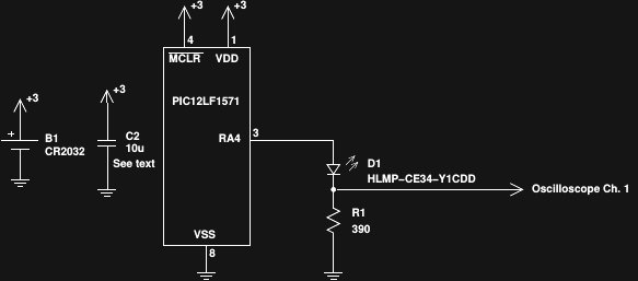
I took the hint from Jaromir and used a modern PIC this time. It's a PIC12LF1571 driving probably the first circuit you ever used with a microcontroller: blink an LED with a dropping resistor. Unlike the introductory-course circuit, the resistor here is chosen to drive the LED at its peak efficiency, which I was able to measure last time. The oscilloscope measures 504mV across the resistor during the pulse, equating to 1.29 mA - right at the efficiency peak for this LED.
The PIC runs at 4MHz from its internal oscillator, and wakes every 16ms to generate a pulse. I chose 4MHz to save power - as it turns out, relatively long pulses are required, so super-accurate timing is not necessary.
To test the output, I compared the LED brightness to a DC-driven one right next to it, as Jaromir demonstrated. I found that by darkening the room, then placing a piece of paper over the LED domes, I could more accurately see brightness differences - it's a primitive Joly photometer. I set the DC LED for a number of current settings, then adjusted the pulse width on the PIC until the brightnesses looked equal. Here's what I observed:
| DC Current | PIC Current | Ratio | Pulse Width | Pulse Current |
| 10 μA | 4.6 μA | 0.46 | 8 μs | 1.29 mA |
| 20 μA | 5.6 μA | 0.28 | 19 μs | 1.29 mA |
| 50 μA | 12.7 μA | 0.254 | 97 μs | 1.29 mA |
| 100 μA | 56.1 μA | 0.561 | 662 μs | 1.09 mA |
You really see two different effects here. At the 10uA DC level, the LED is abysmally inefficient, but the PIC version has the microprocessor overhead dragging it down, so you can only save about half the power with the pulsed version. At the 100uA DC level, the LED is starting to become reasonably efficient, so the PIC gain isn't that great - again, you save about 50%. In between the two extremes, at the 50uA DC level, the pulsed version consumes only 25% as much power. If this level of illumination is sufficient for your task, you can gain 4x the run-time.
The pulse current droops a bit during the 662us pulse - long wiring and not enough capacitance on the breadboard. I added a 330uF Al-polymer cap to smooth the supply out for the last test.
At 100uA DC (or 56 with the PIC), these LEDs are pretty bright - more than enough to read by in a dark room:

This simple circuit does pretty well for itself, as long as the battery stays around 3V. The forward voltage of the LED at 1mA is around 2.5V, so there's not much headroom. Lithium batteries have a fairly flat discharge curve, but CR2032's aren't typically considered "dead" until 2.0V, which wouldn't light these LEDs at all. For that reason, I don't think the simple circuit here is useful as a practical glow marker. Instead, it demonstrates the value of designing for peak LED efficiency. If the same can be done for the other topologies I've been thinking about, then those will probably see a similar improvement.
Just for reference, a CR2032 battery would run a 4.6uA device for over five years. Of course, this circuit would cut out long before then as the voltage dropped, but it's a hint that the run-times might be extended considerably from the 1 year of Version 1.0.
Discussions
Become a Hackaday.io Member
Create an account to leave a comment. Already have an account? Log In.