So the last component I needed, the female to male ethernet cable, showed up, so I was ready to start building!
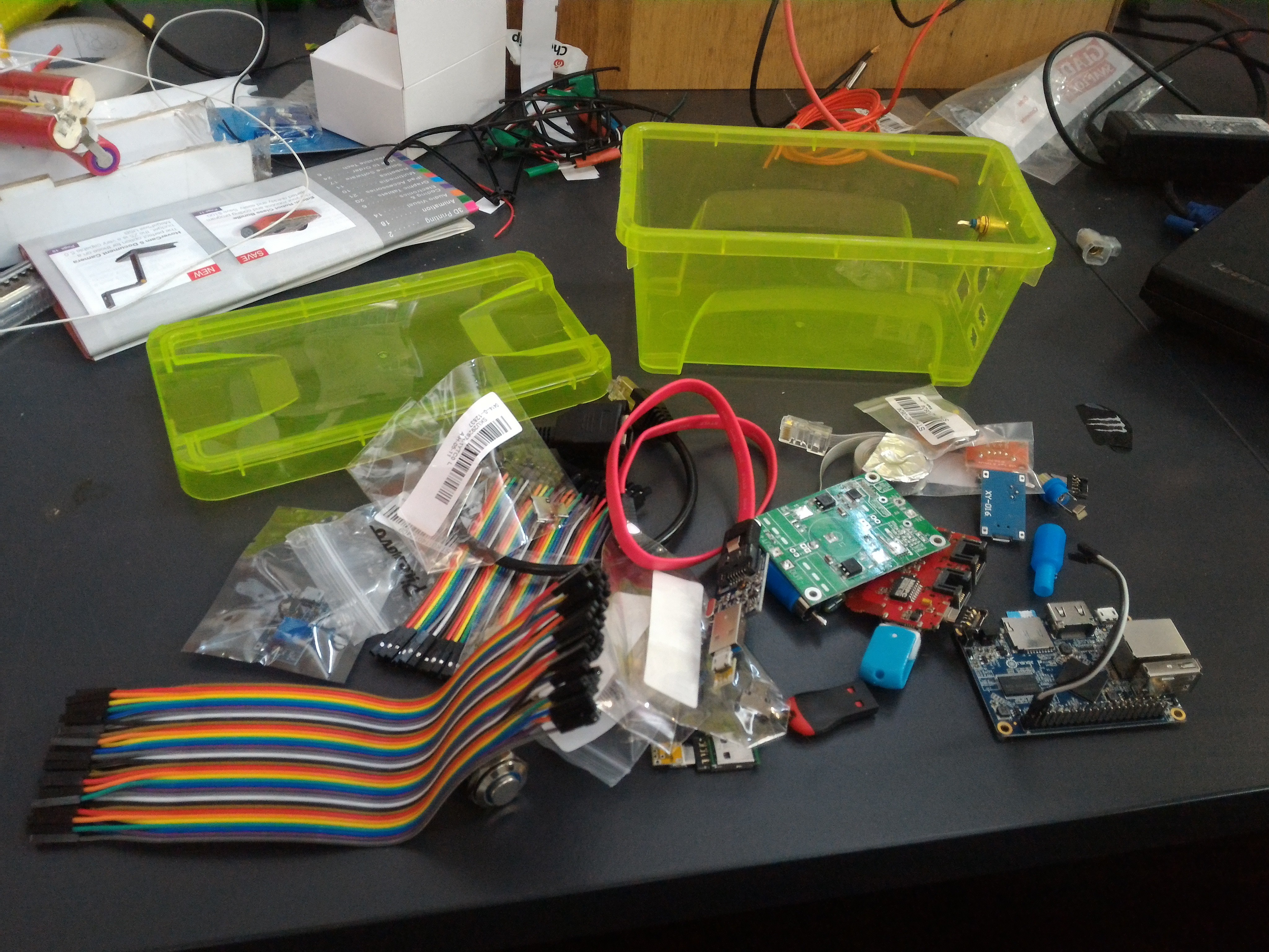
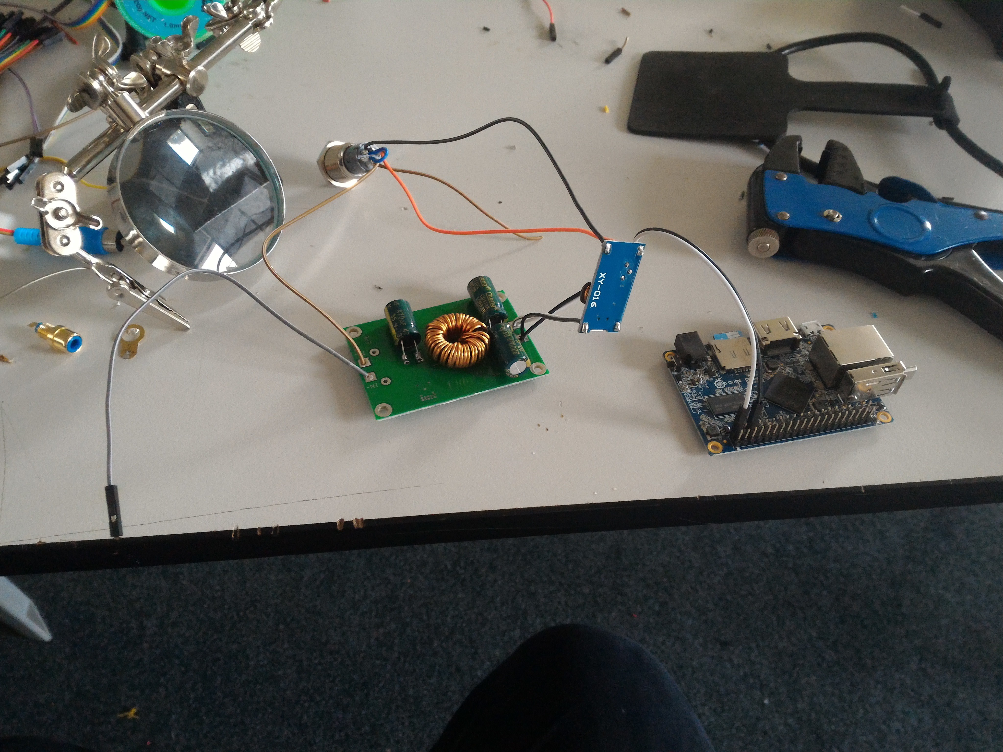
Well, better do some layout testing first (I actually did this long before this log but gotta throw it in somewhere (Well, all the logs so far were posted after the project was completed but you get the point. This was out of order. See: Lack of box mutilation. (After this log anything I post will be live, but who knows what else there is to do. More cases?))).
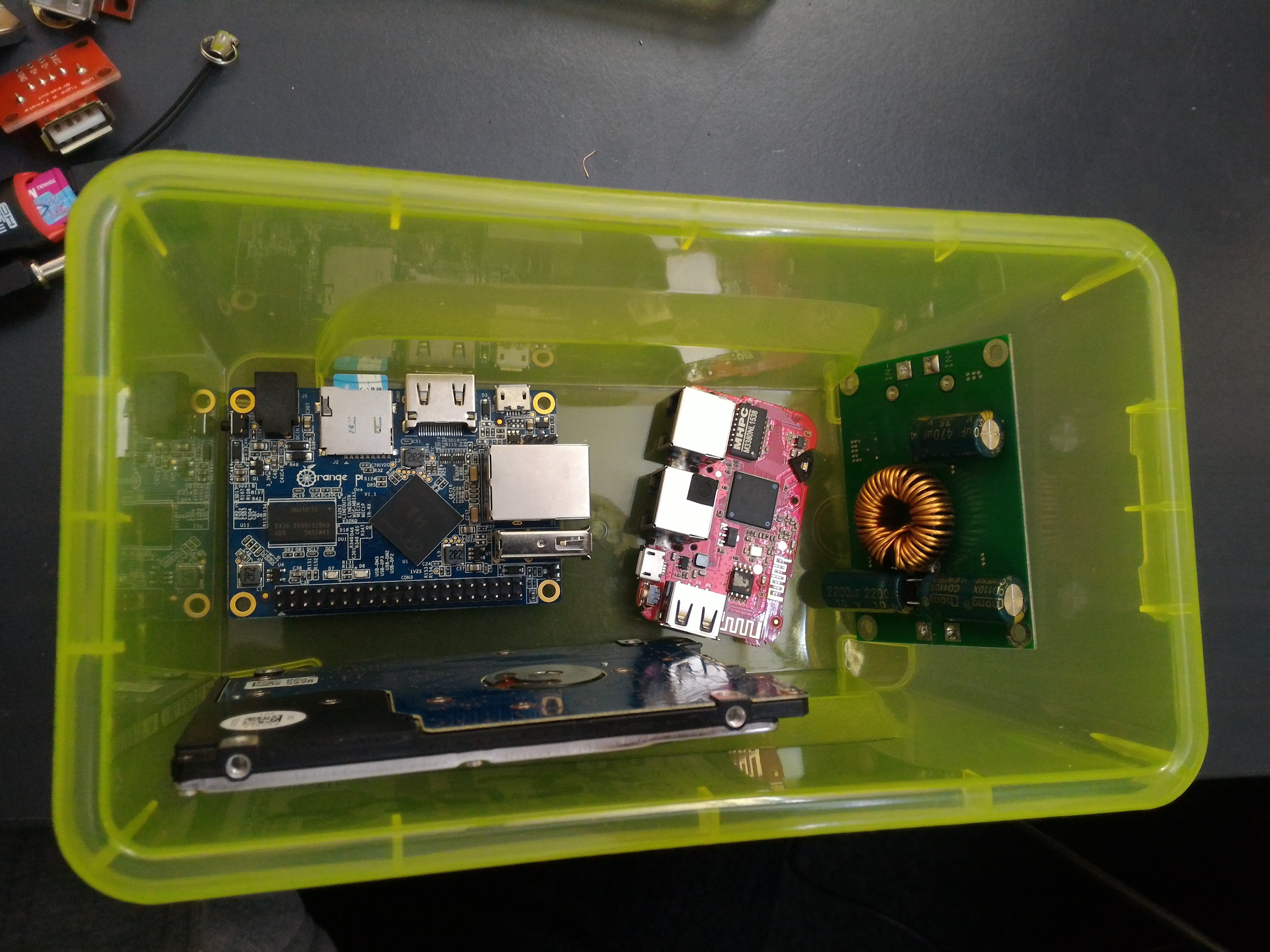
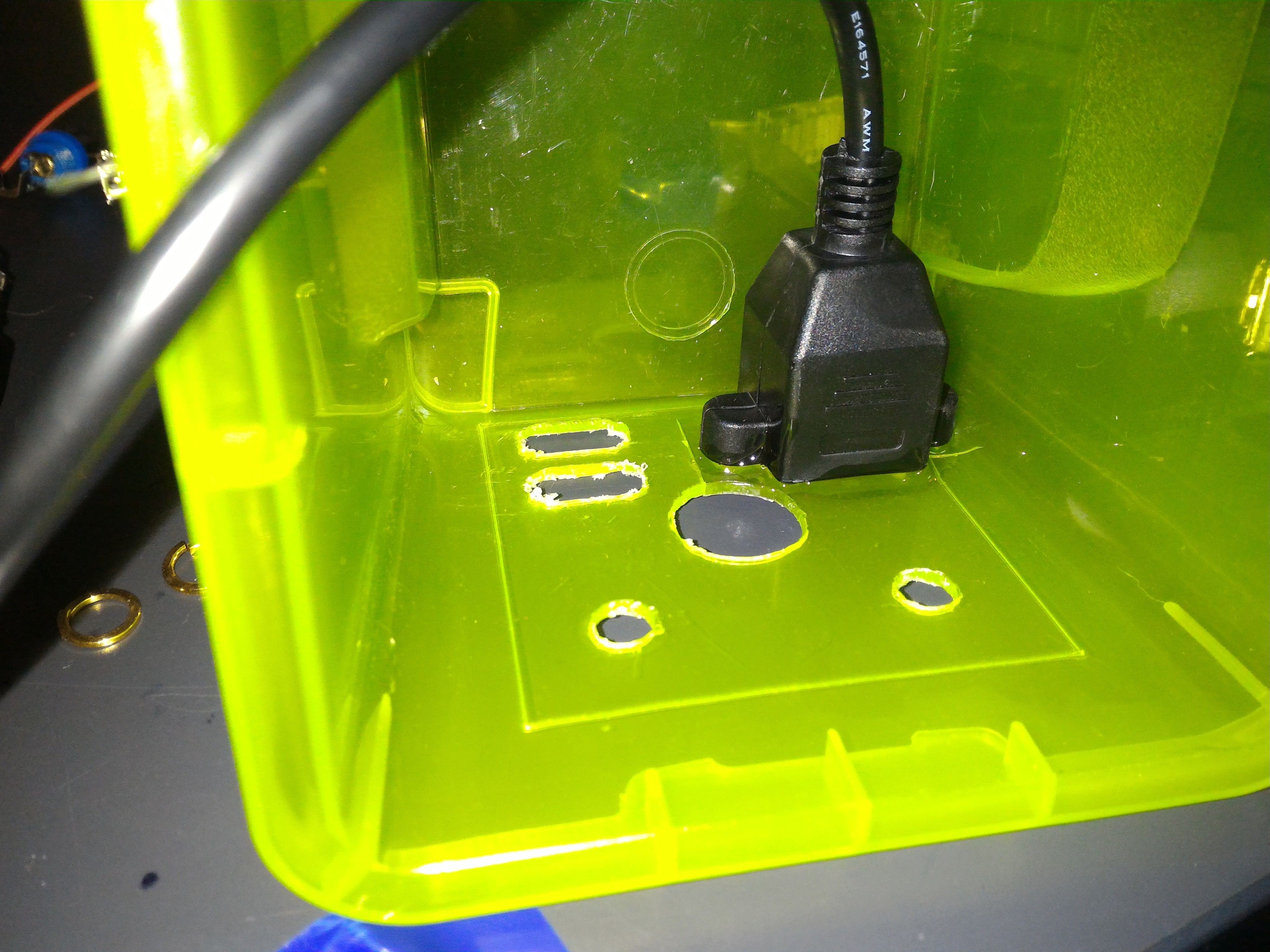
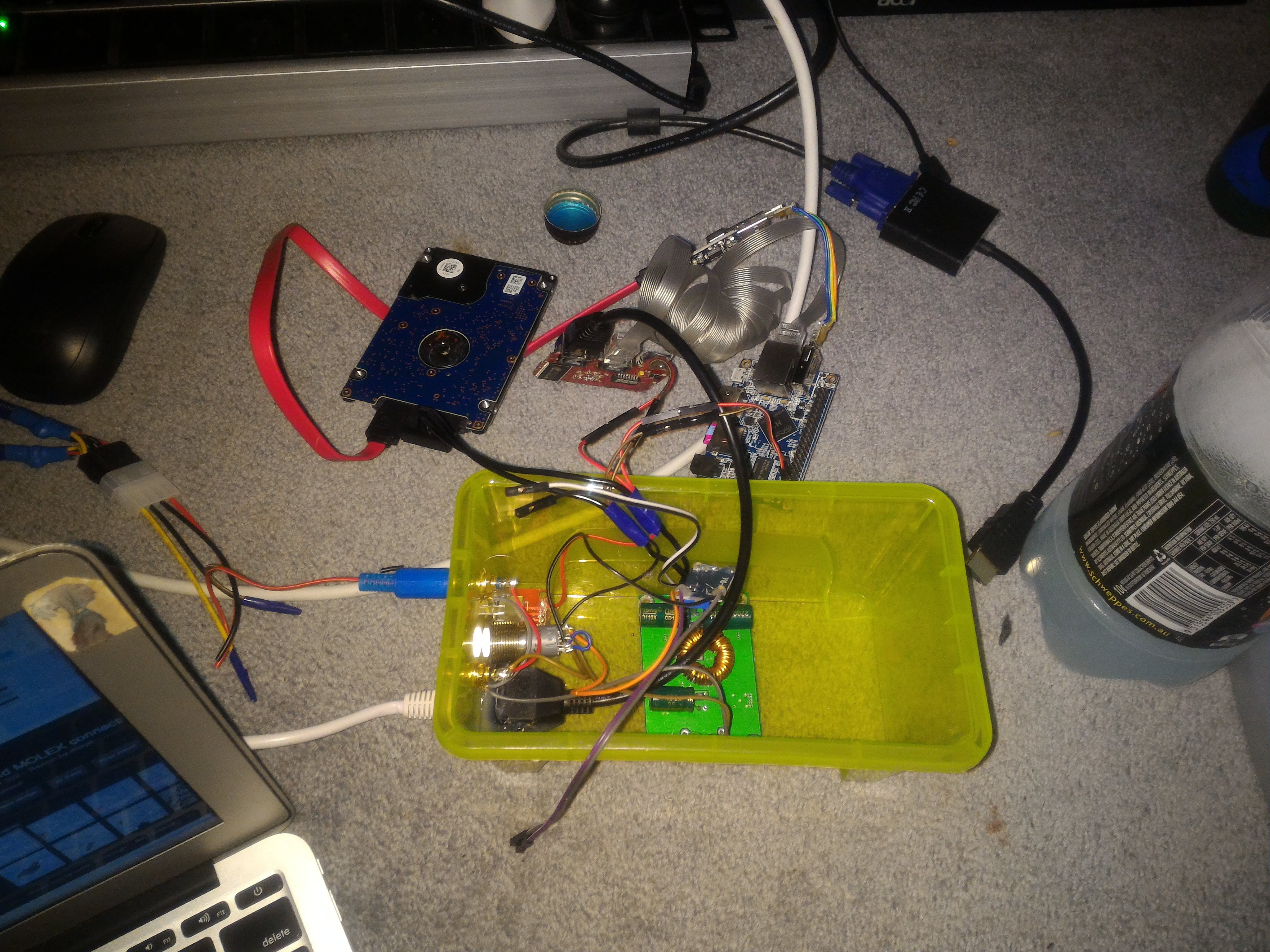
This looks good
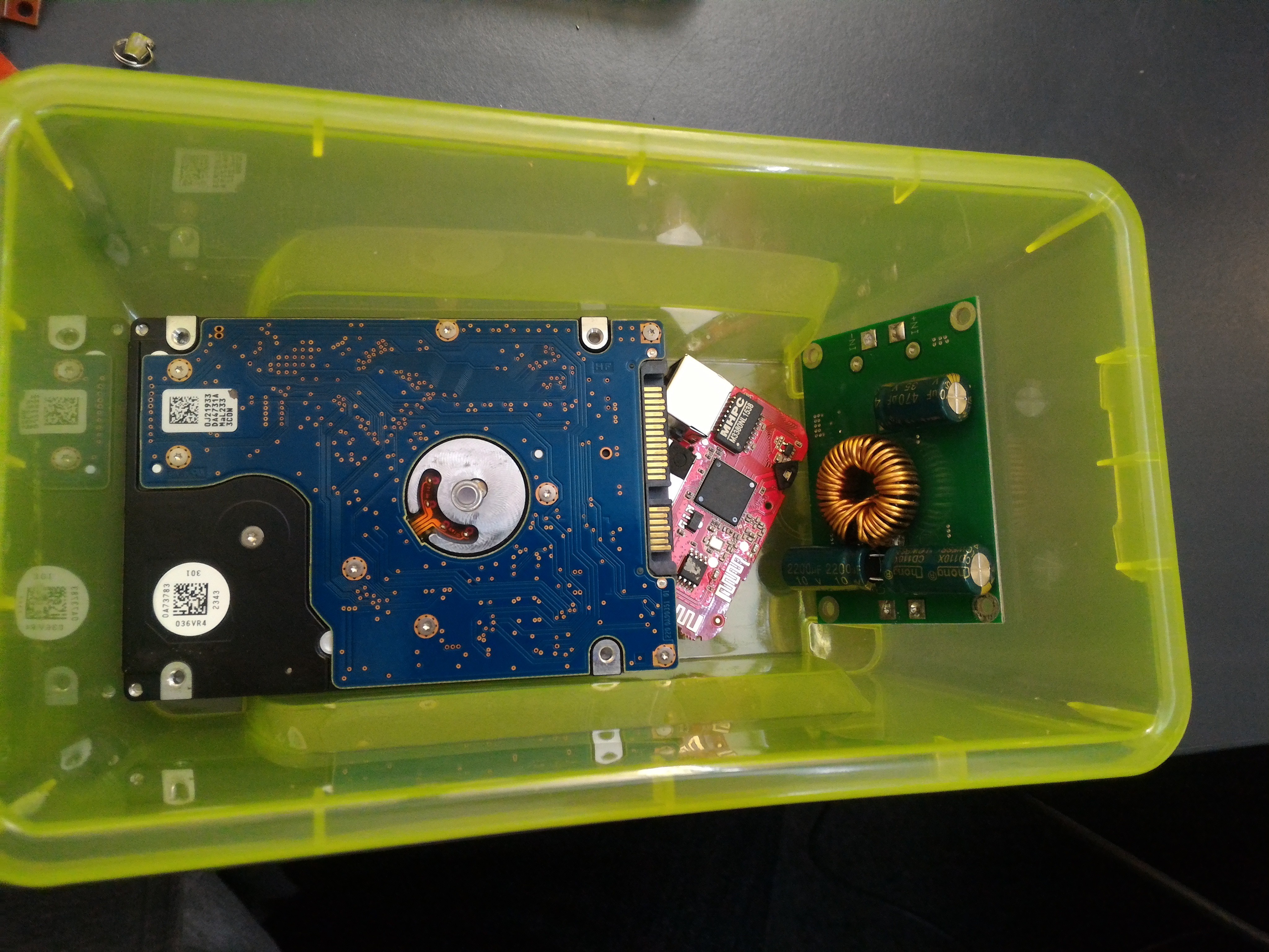
Ditto. Looks like it'll be dead easy to fit all this in however I needed to.
Also this because I think it's cute. CUTE.
So, time to start gluing!
I told myself I wouldn't use hot glue in this project, but because I couldn't/didn't want to screw the ethernet jack in properly as the plastic of the box wasn't exactly pleasant to work with, I needed to compromise, so super glue it was!
Okay, maybe buying the cheapest homebrand glue I could find wasn't a great idea, on reflection the packet didn't even say it did plastics. It took forever to dry and was cloudy, so I doused it in hot glue. I'd already lowered myself when I used the plastic box, I figured this wasn't all that much worse.
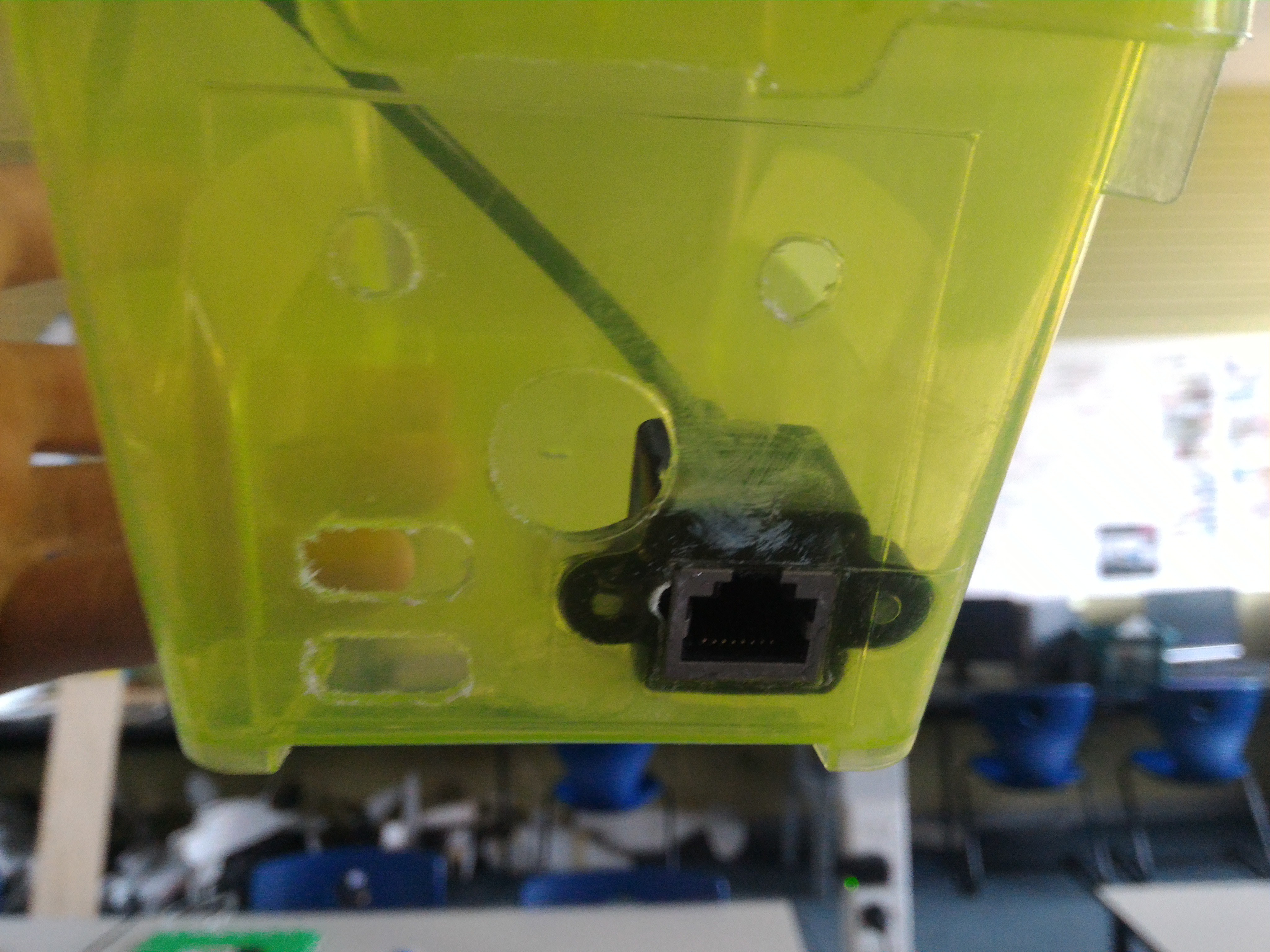
Cloudy and garbage.
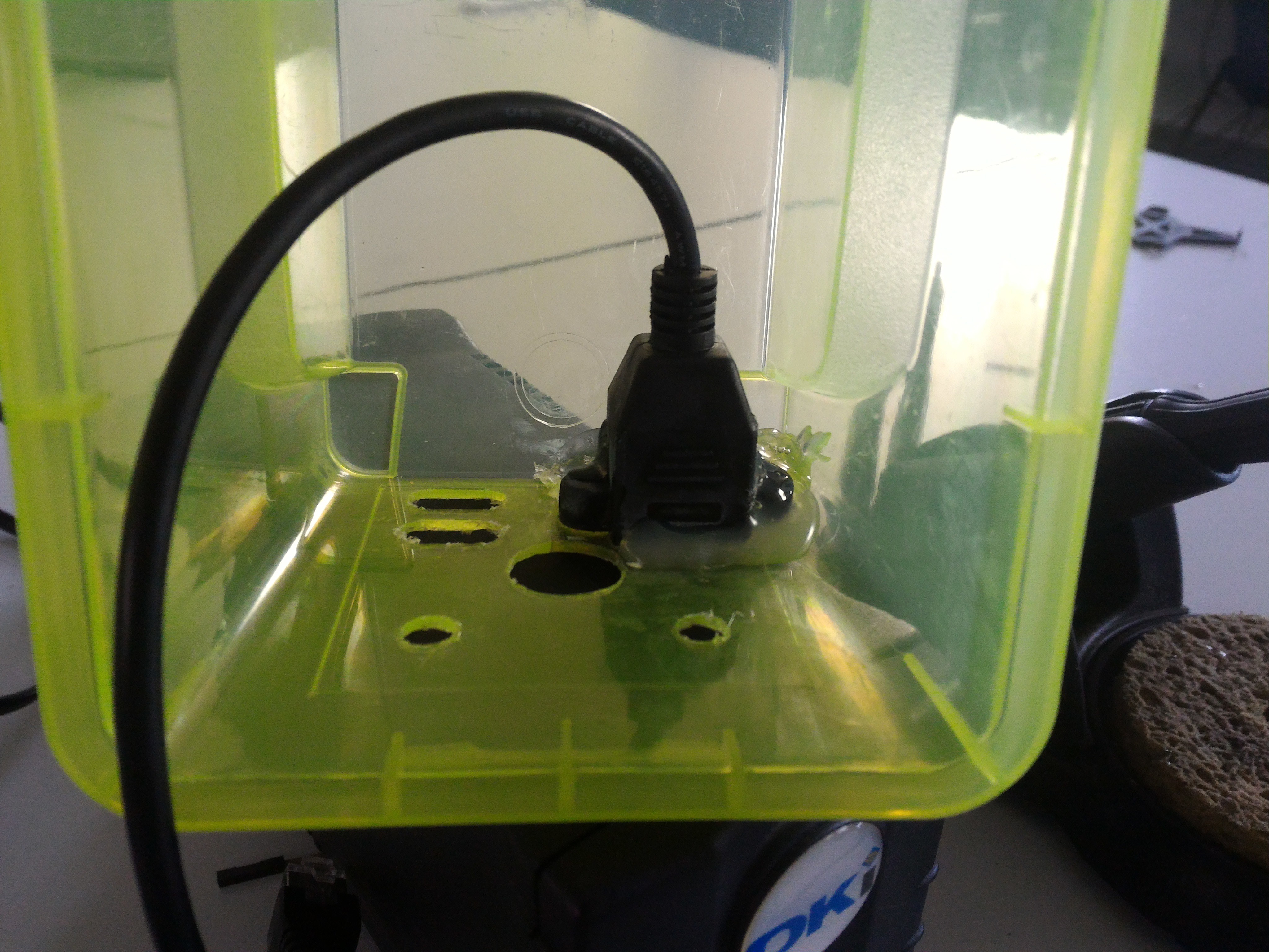
There. Hotglue hides everything.
Now, let's get those USB ports ready.
Purely for the sake of charging, there's no need to have the data pins connected to anything, so I shorted them. Tales from the riverside say this can tell devices it's okay to draw more current than spec. I really need to test that some day.
All jumped up.
Both ports being stacked and already broken out meant that it could be a little hard to wire them up, so I'll just try my best.
Semi wired up.
All wired up.
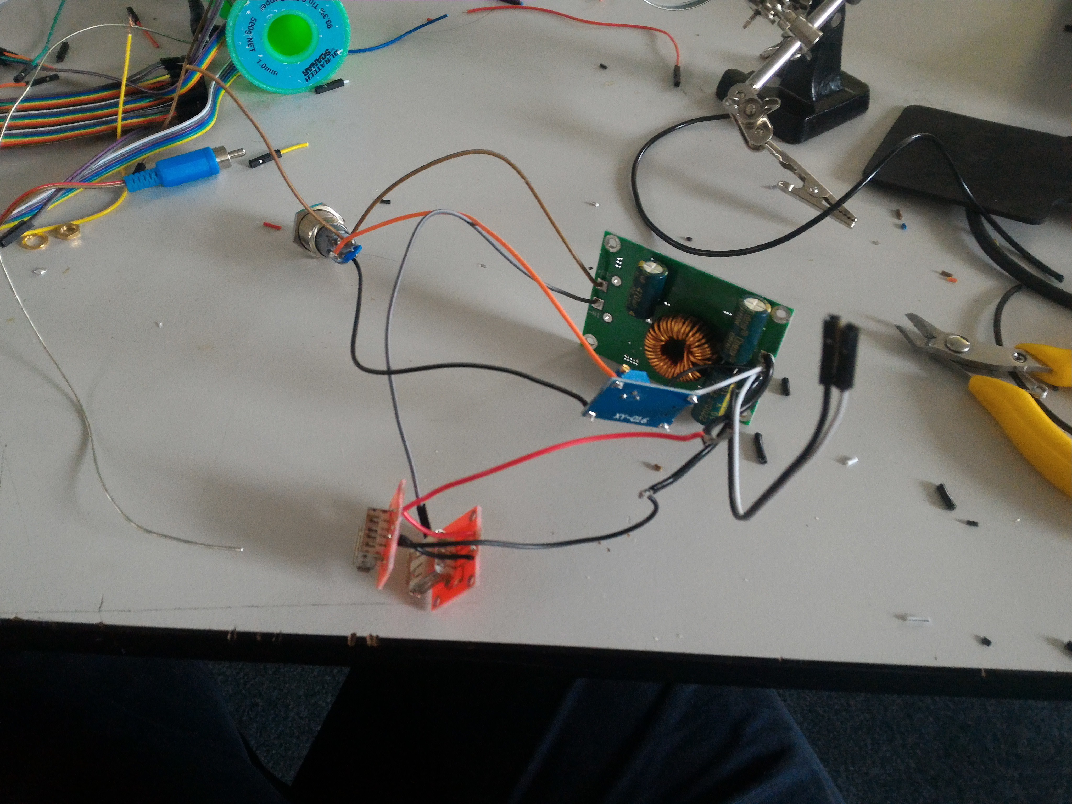
Time for the power button.
I cut off the unneeded pins, all I was left with was Common and NO pins for the 12v input, two pins for the LED, and Common and NO for switching the LED.
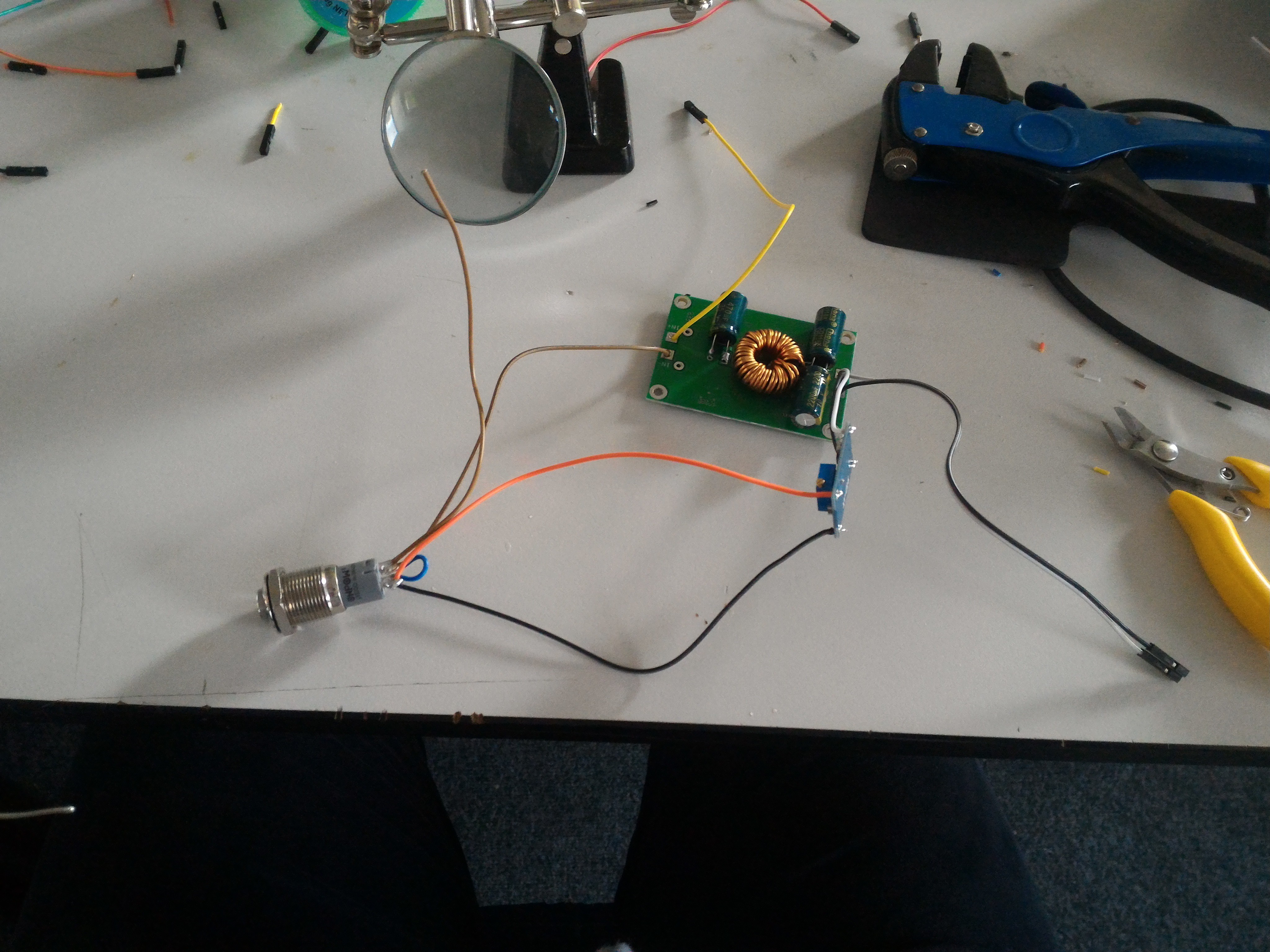
I decided not to put the LED on the main power in, as on solar it could range from 10-15V.
Instead, I stepped the voltage down to 5V, then back up to 12V. Gotta be safe.
Anyway, I soldered onto C and NO for the main input, + for the LED's positive, jumped the LED's - to the second common, and soldered a wire onto the second NO to go to negative 12v filtered.
Switch wired up.
Not much to say here, just connected the switch up to the step down. Spare switching the negative, not positive, se eh. Also the switch goes through the front of the case, so double eh.
I know it's DC and not switching positive's not as much of a deal as with AC, but I still like to. I fixed that all up later.
See also: the little board on the side. That's the 5-12v step up.
It had a micro USB plug on it, so that's nice. I'd rather have used one without, as they're cheaper, but they still haven't shown up yet.
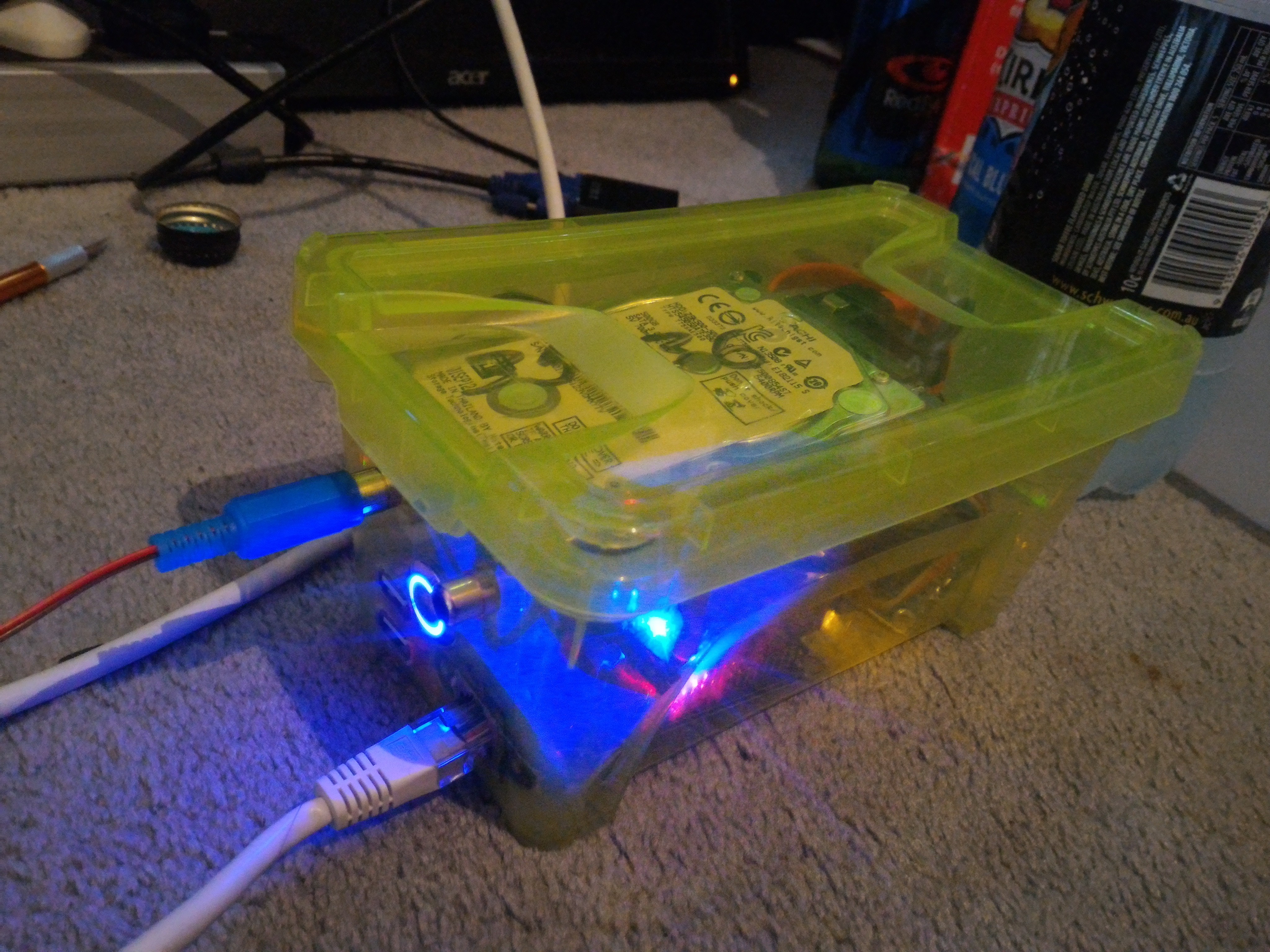
 And all working!
Tested on the oppai, and it seems to power up like a dream! The oppai had been sitting in the box for a fair while, I didn't know if any of the traces had been scratched or anything, so if it actually works, and if enough currents provided (or if my 50w step down's just junk), well, that comes later.
 USB ports wired up.
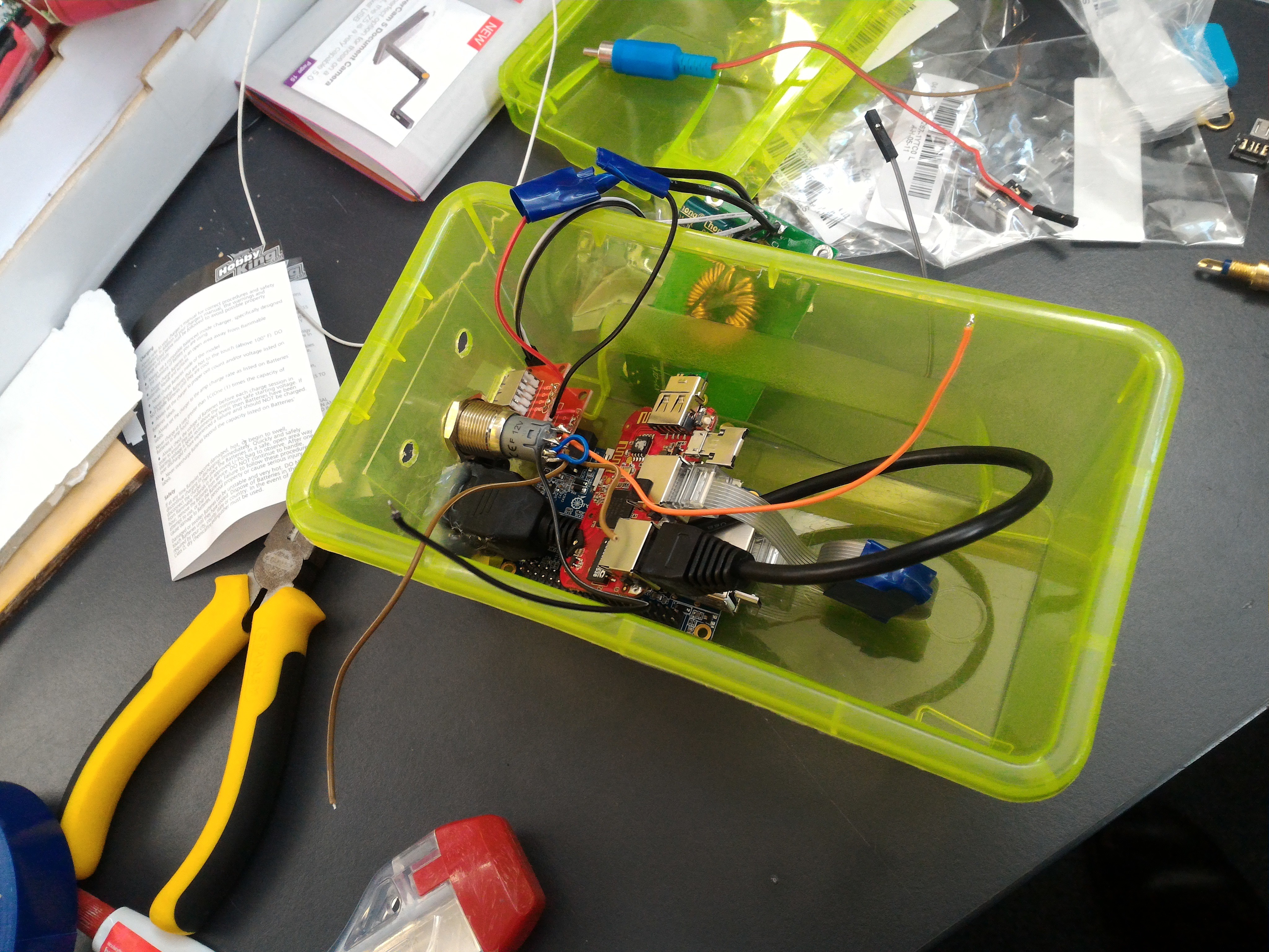
Starting to take shape.
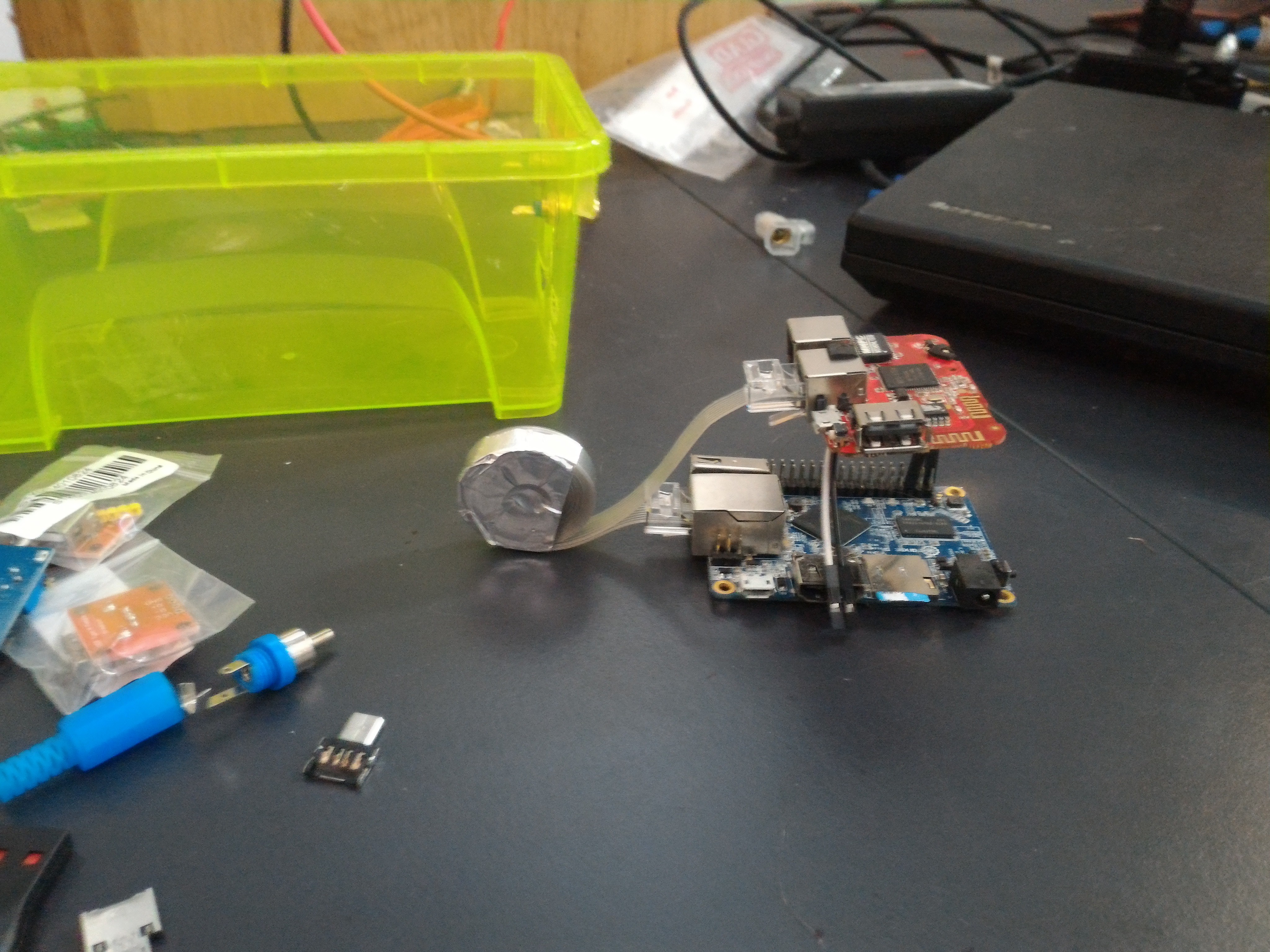
Now, for the USB to sata adaptor.
There wasn't the space to just plug it into the oppai, or to use a regular usb extension cable, so it's improv time.
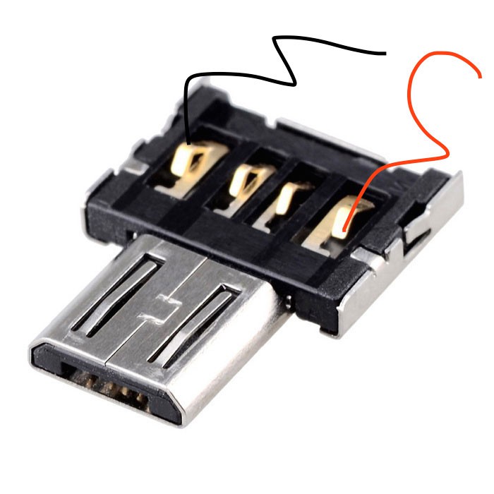
I took one of these little things:
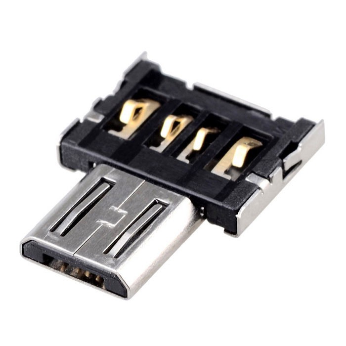
(Little thing, big image)
...and shoved it in the female usb port on my oppai.
It's designed to snugly fit into a MALE usb plug, so it was pretty loose in there.
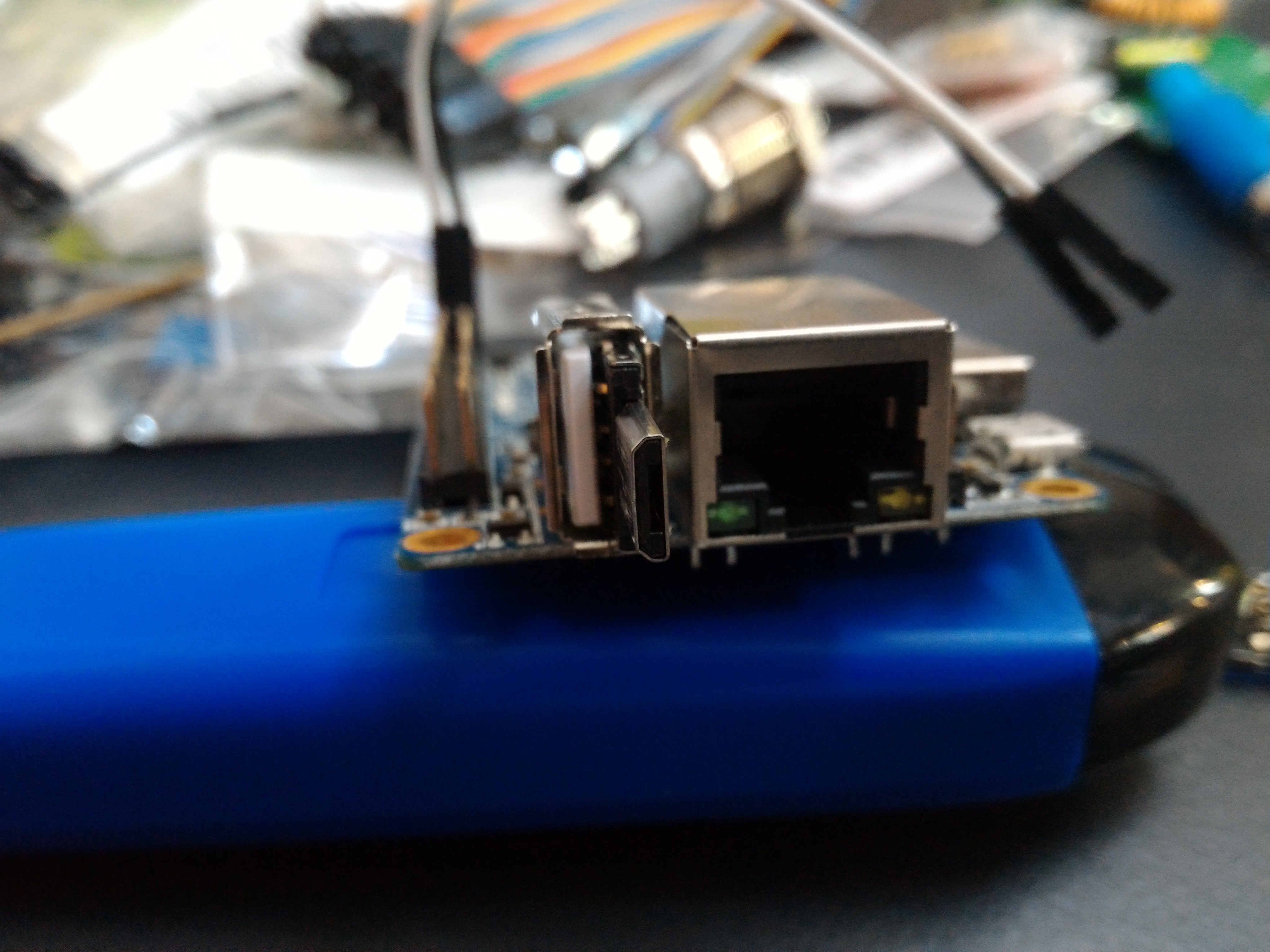
Notice the visible connectors between the tabs.
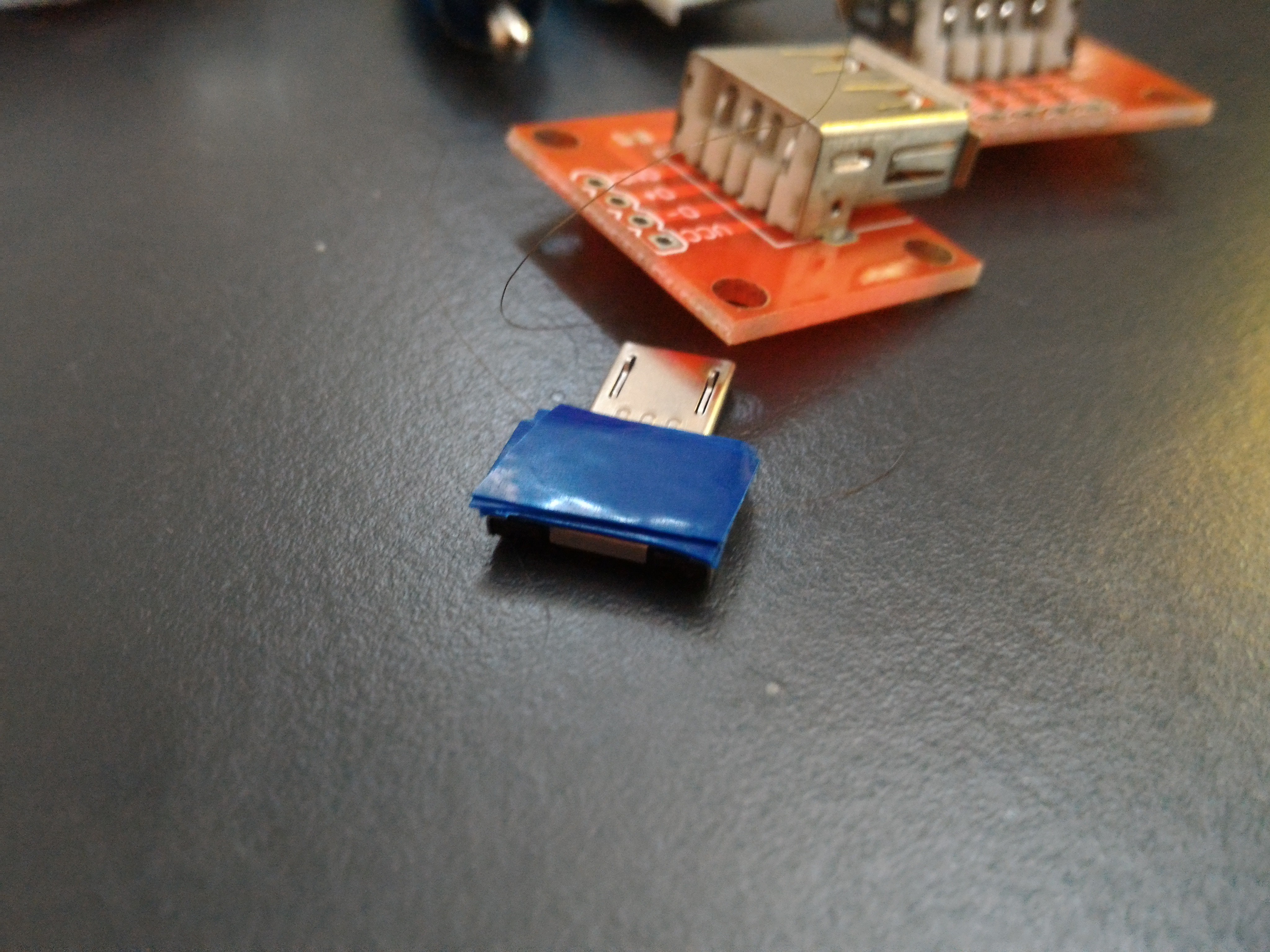
Electrical tape to the rescue!
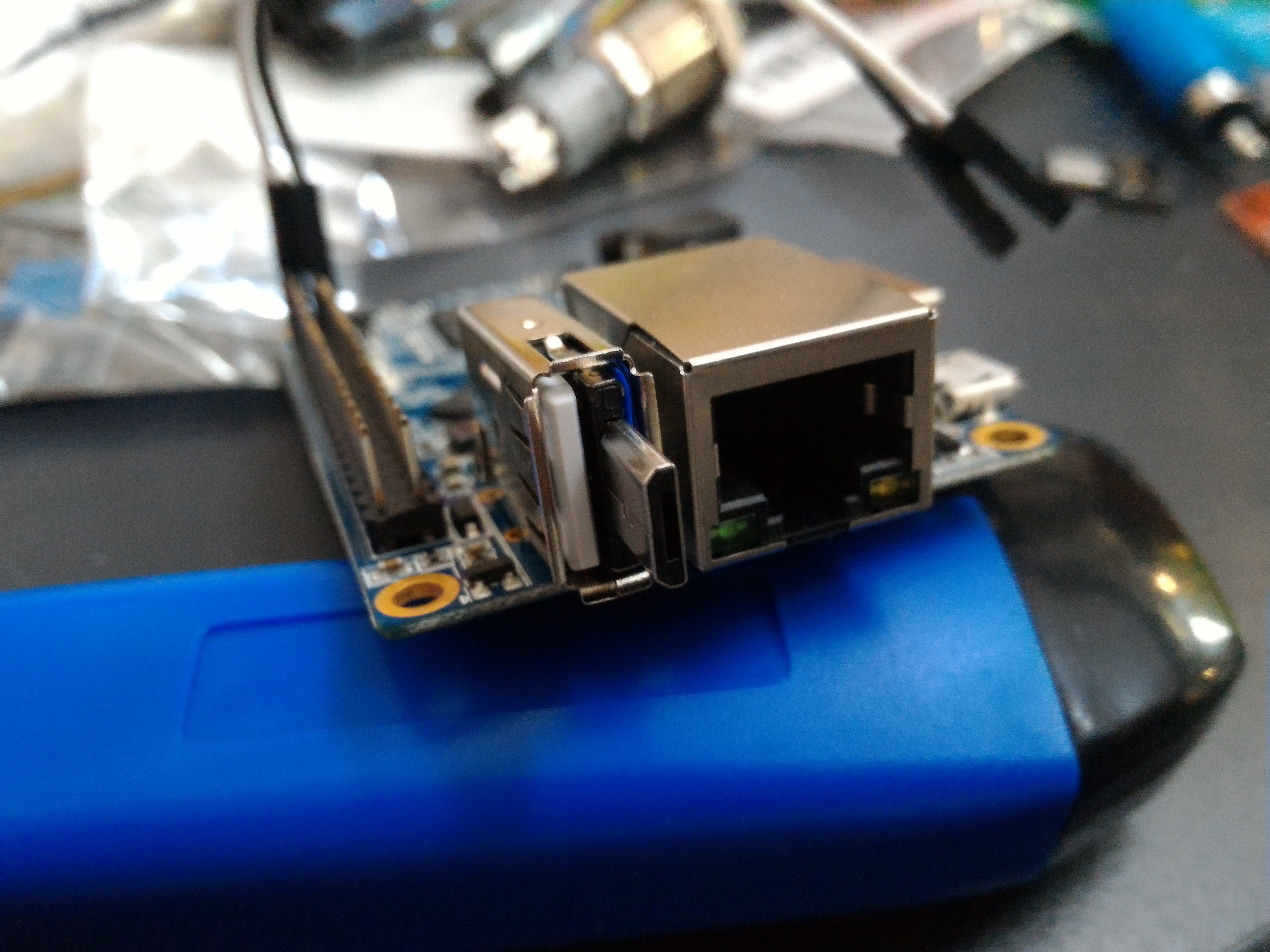
COMFY!
It still has a little slop, but only forwards and backwards (which was a problem later, but nothing worth noting). All good.
The same type of OTG connector would fit snuggly into the USB to SATA board, and with a breakout I could join them pretty easily.
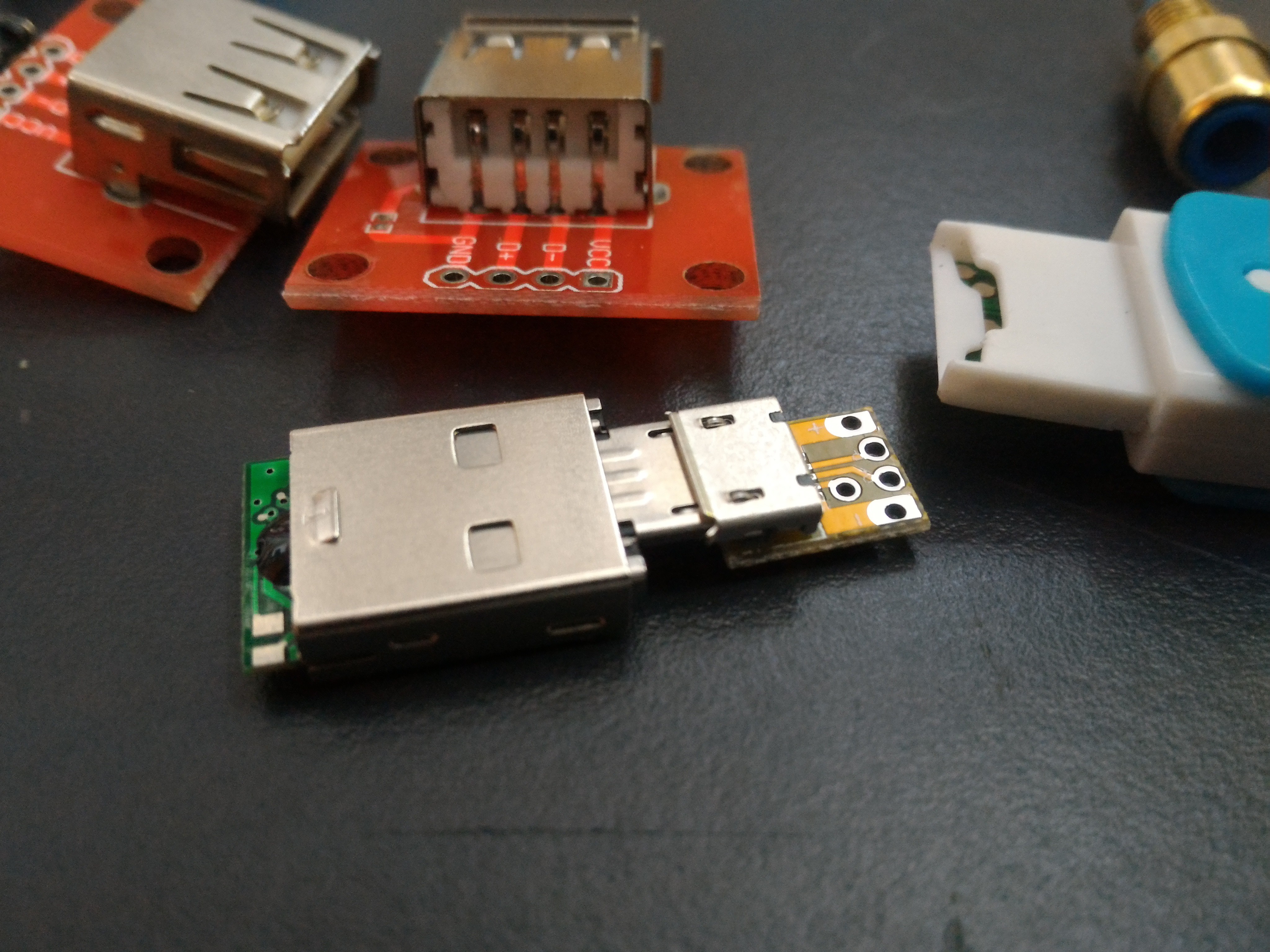
(Not the sata adaptor, a micro SD card reader, but whatever. Didn't have pics of the SATA)
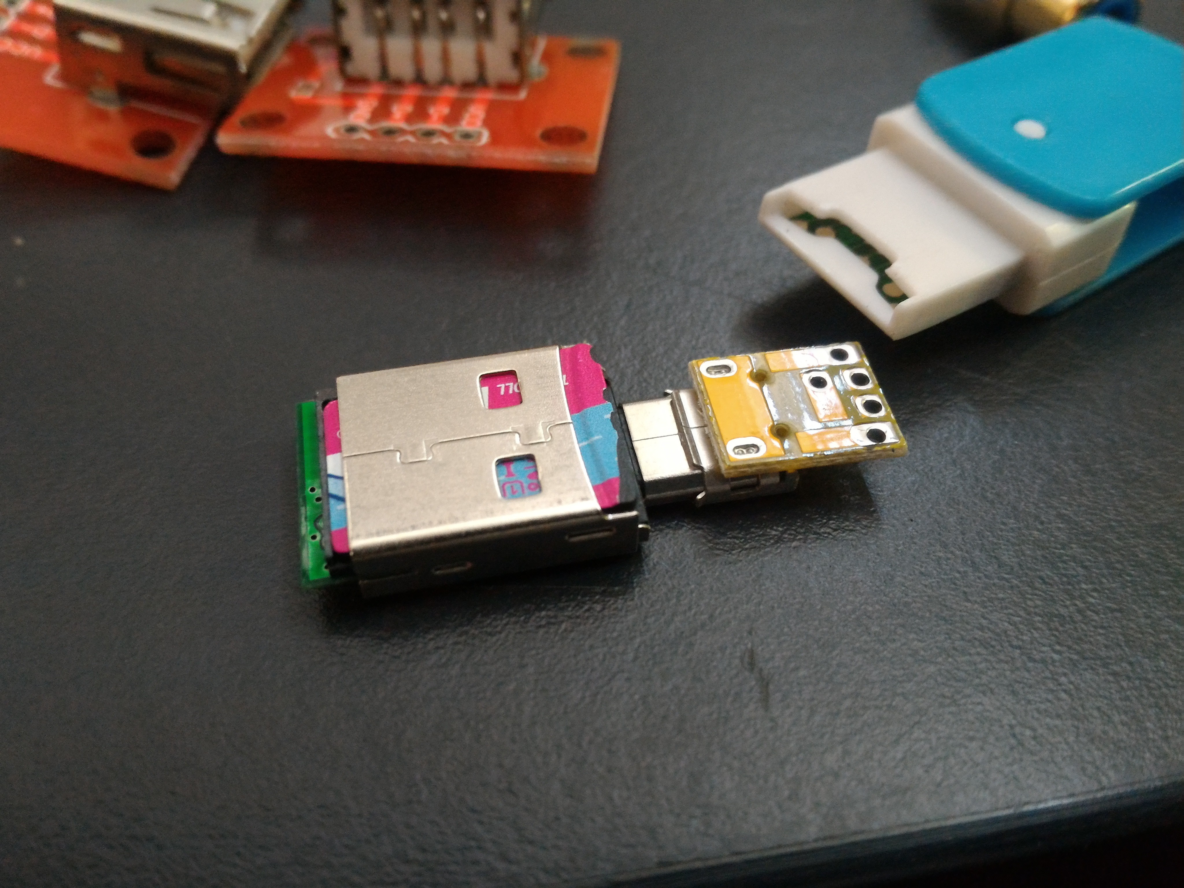
Ditto
Now, time to connect it up.
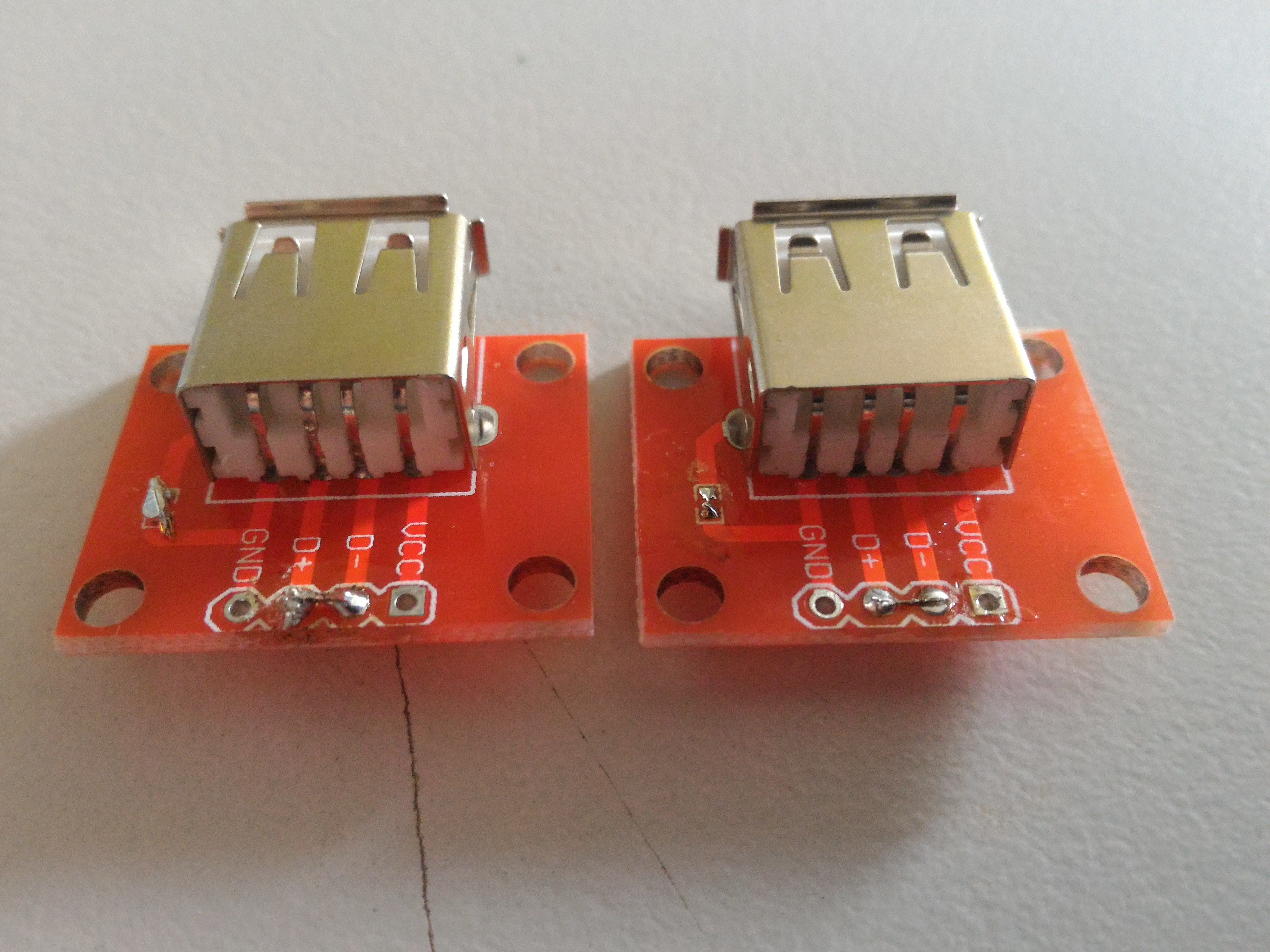
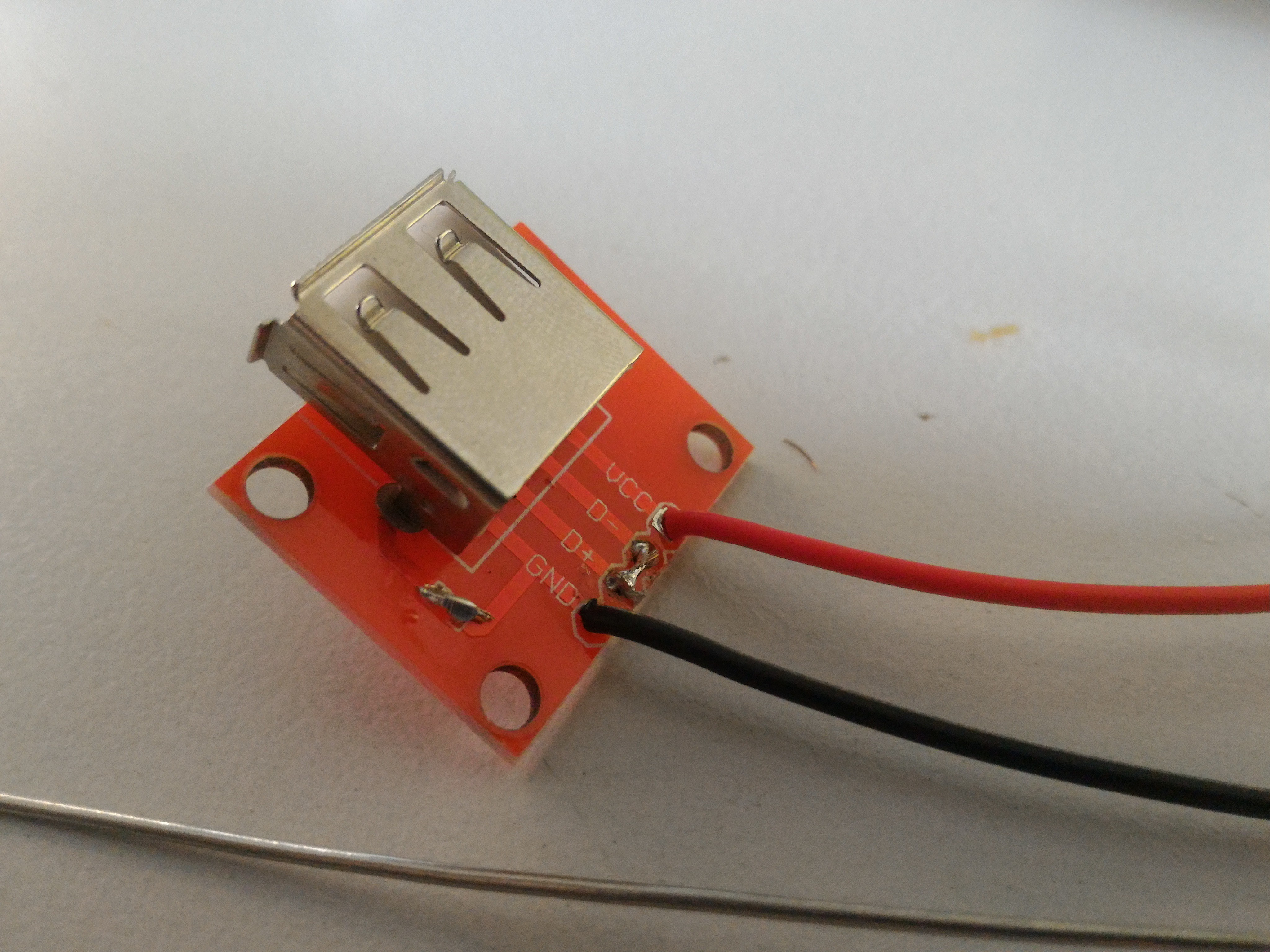
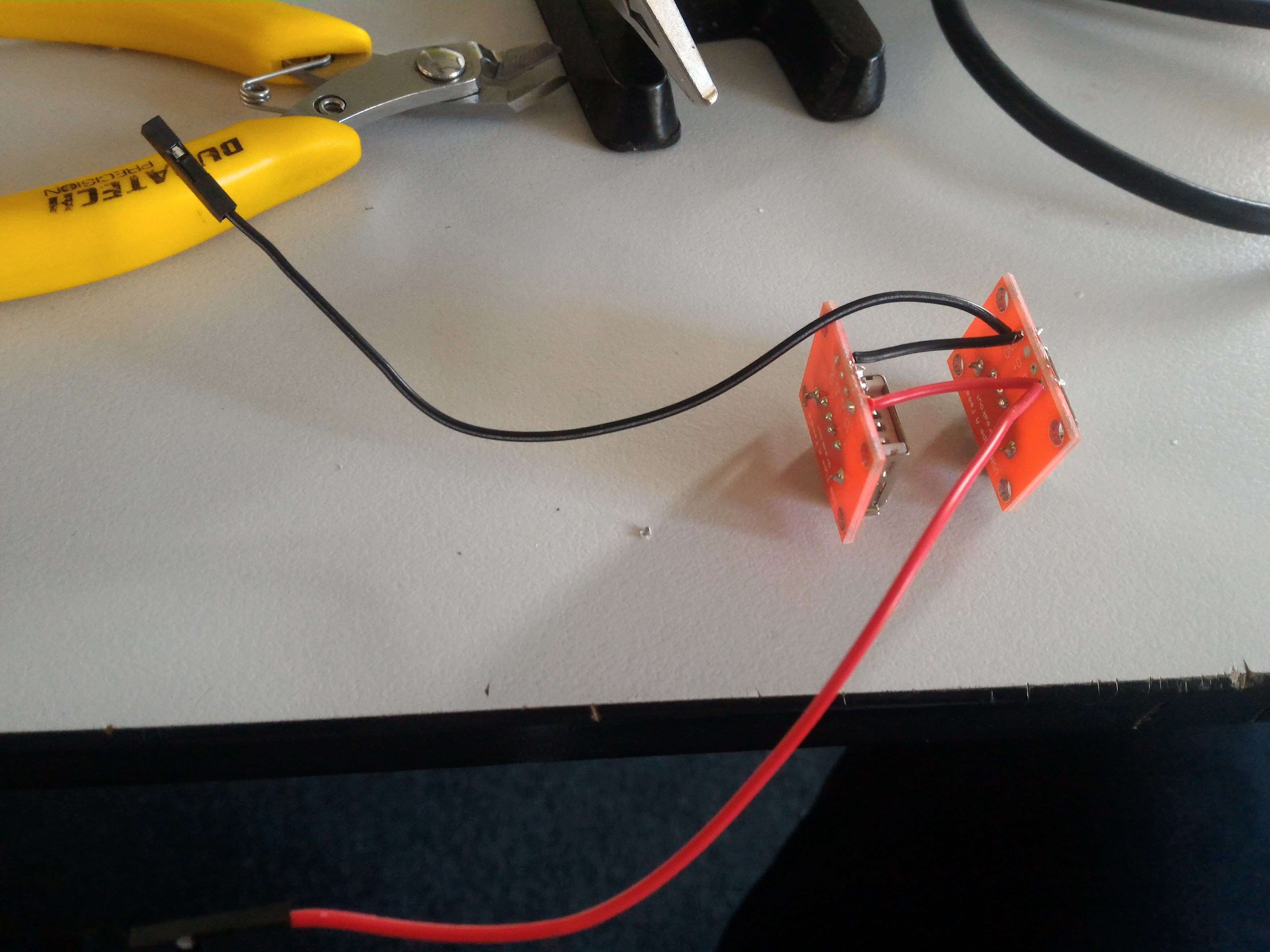
I took the two little female micro USB breakout boards and simply soldered some wires directly over. GND to GND, VCC to VCC, D+ to D+, and D- to D-.
 There's the cable.
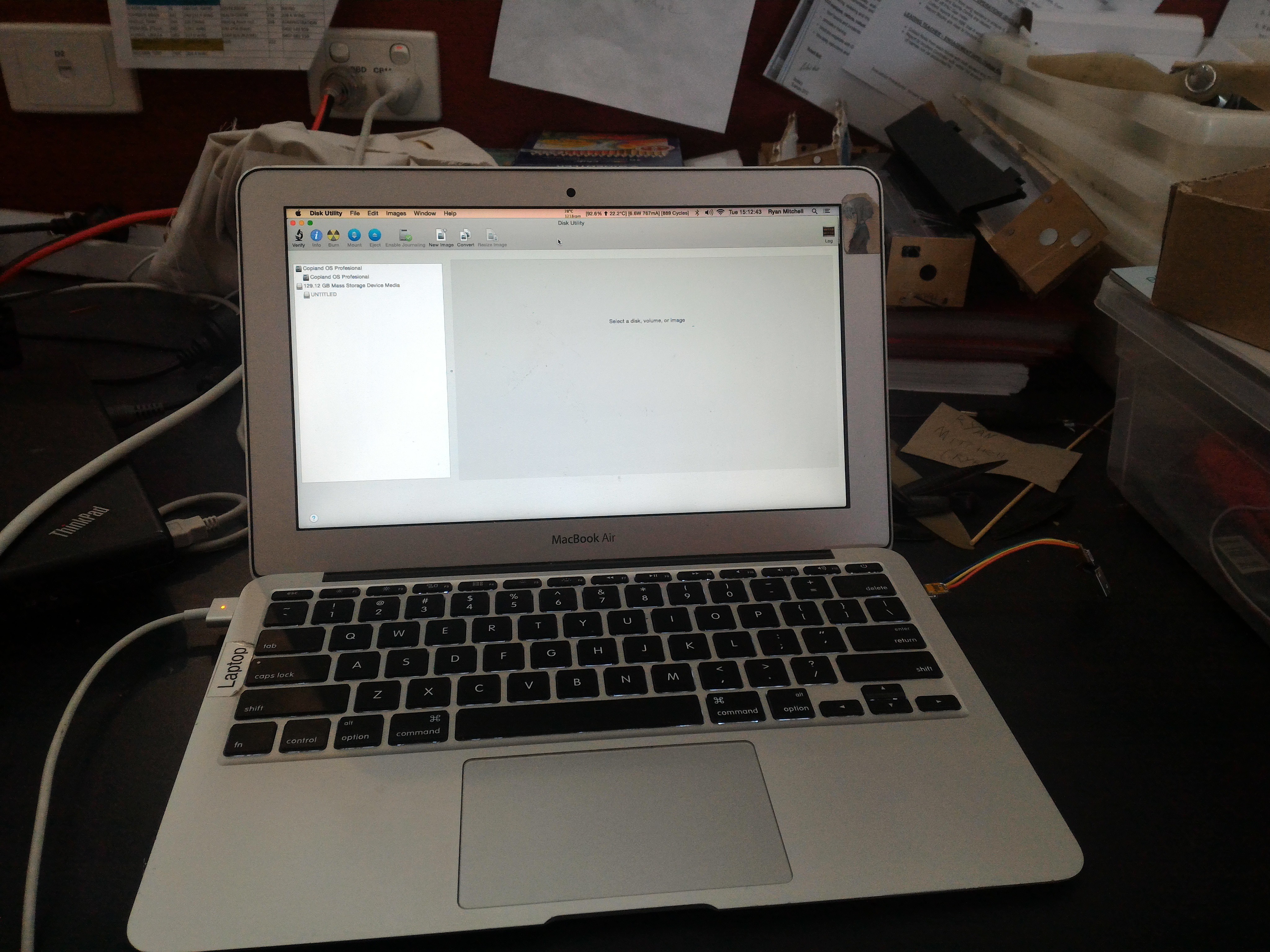 Best of all, it actually works on my laptop. Yay!.
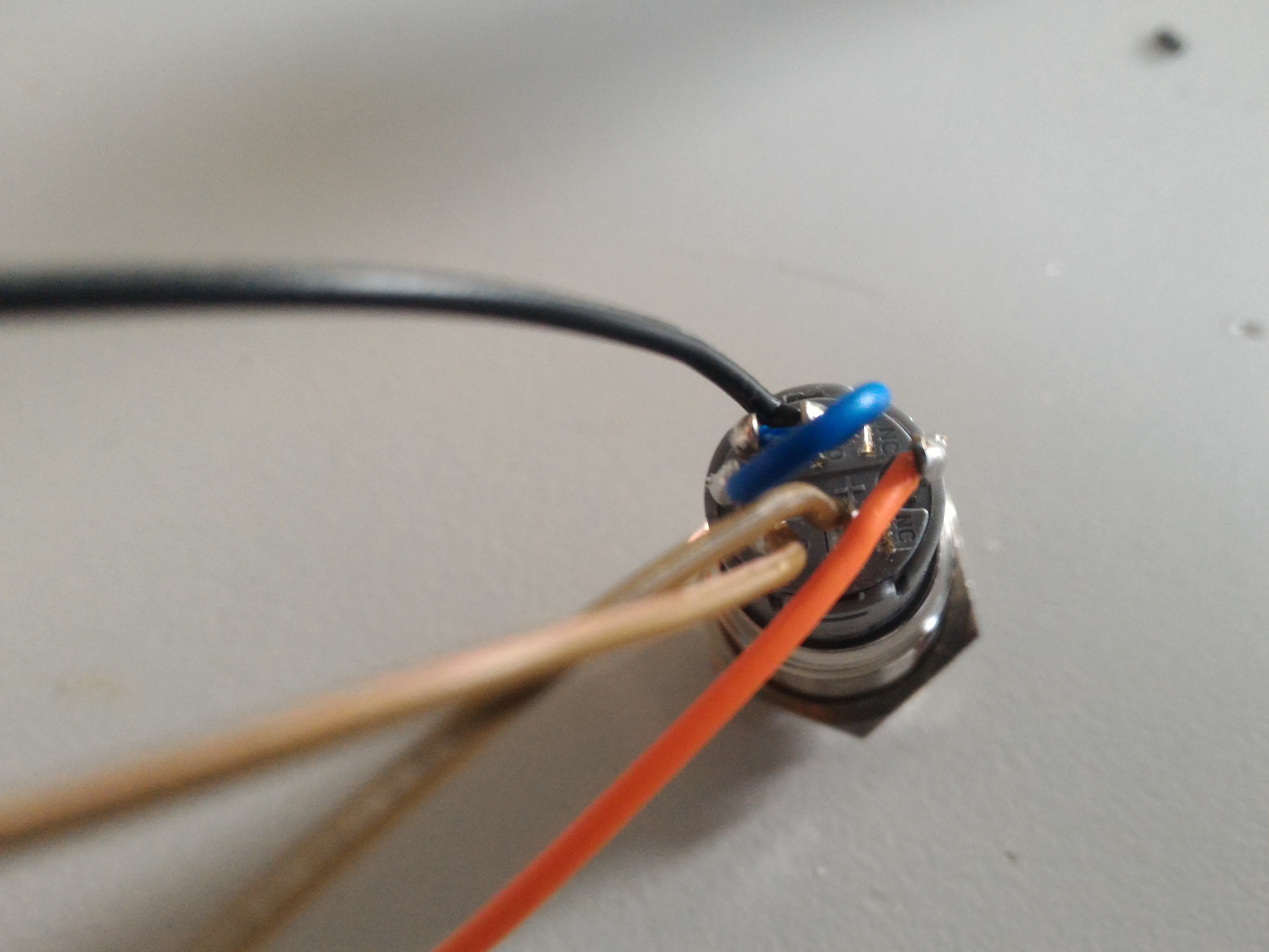
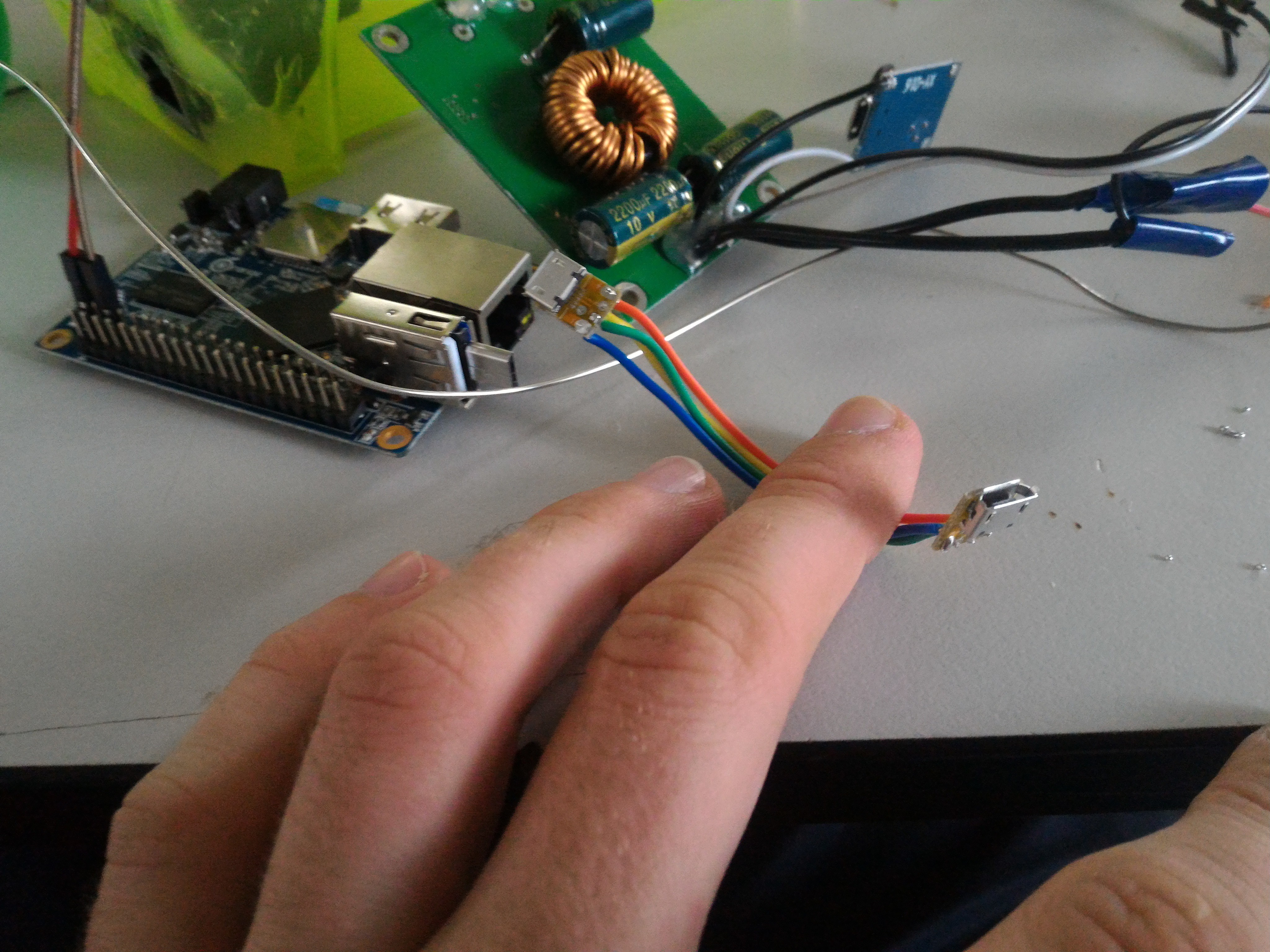
One last thing I forgot to take a picture of before we're done, how I powered the router.
Again, it uses the ever handy USB OTG thingy, but slightly differently.
This time I soldered two wires onto the male end to turn it into a tiny micro USB power cable.
I don't have a clear pic, and there;s no way I'm taking my box apart now, so you'll have to do with these:
(Full picture later, you'll know which one it is)
(They're very clearly wires, duh!)
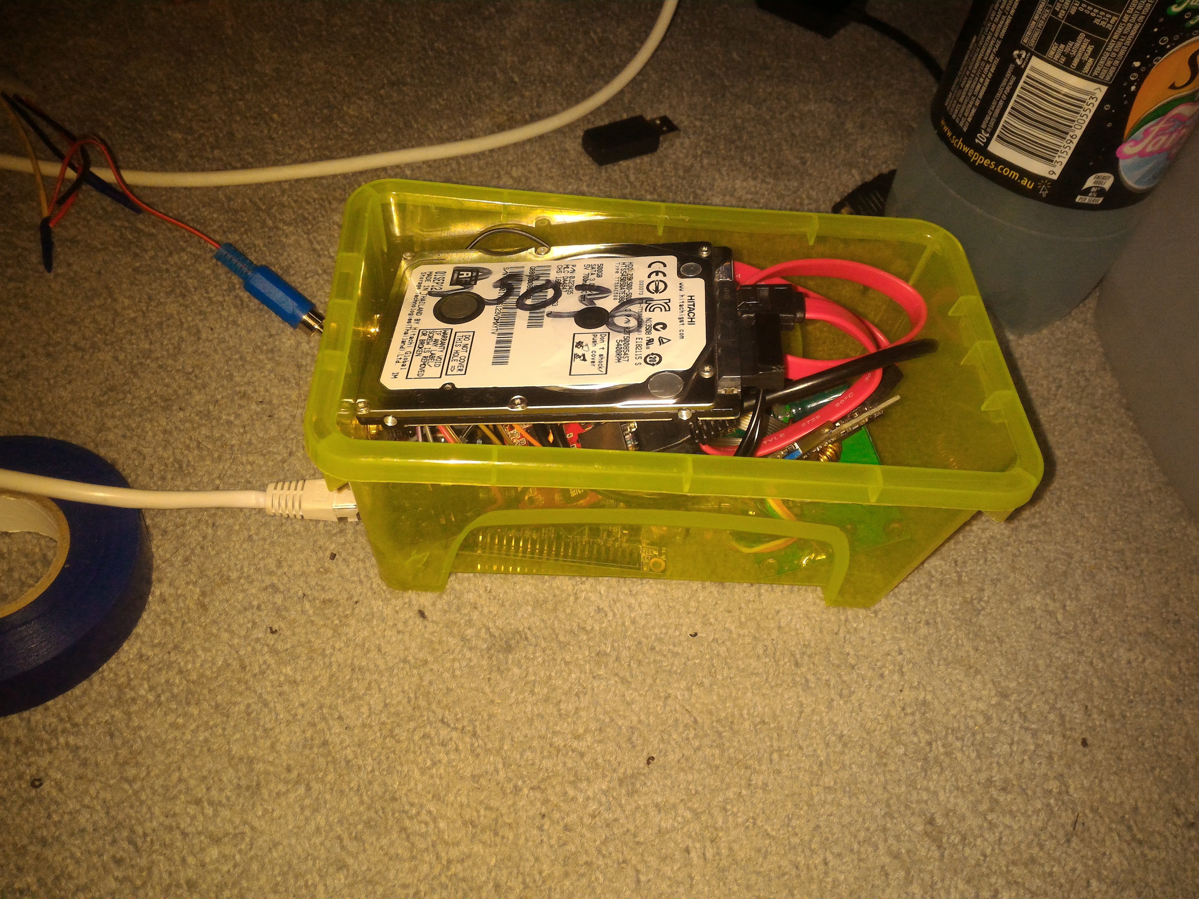
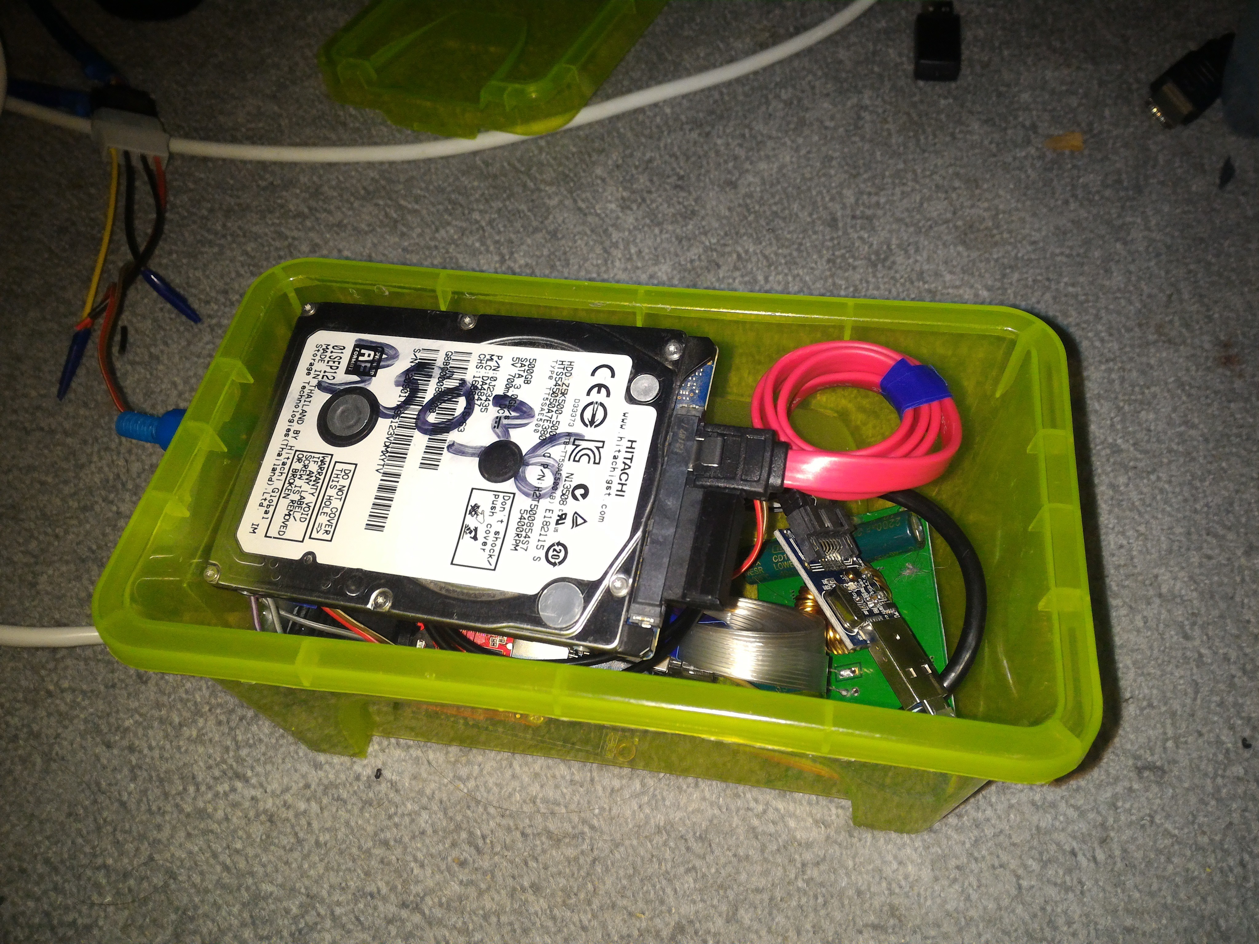
Anyway, that's all there is, now just J-J-J-JAM IT IN!
What's so hard about that? Expensive legos...
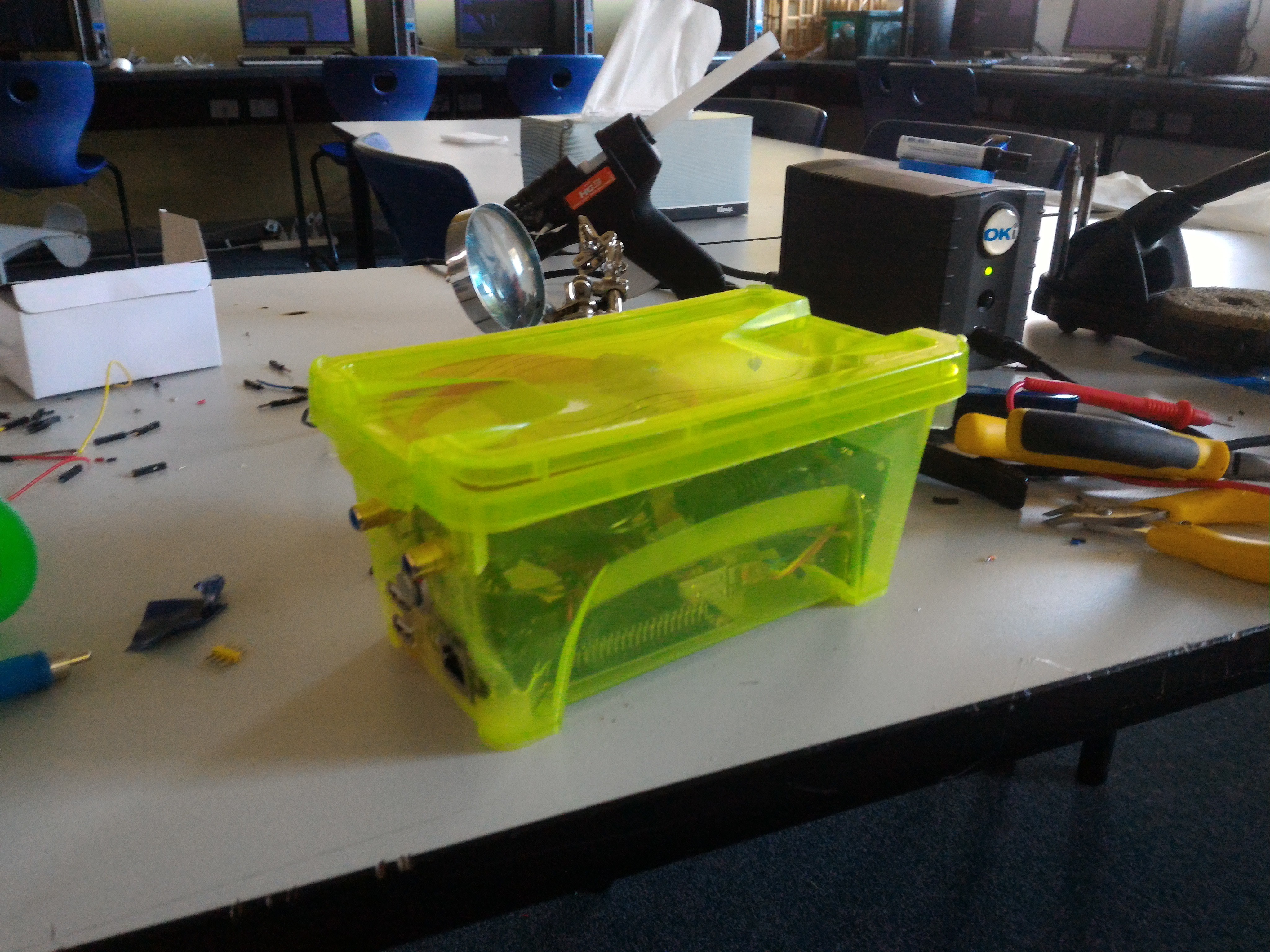
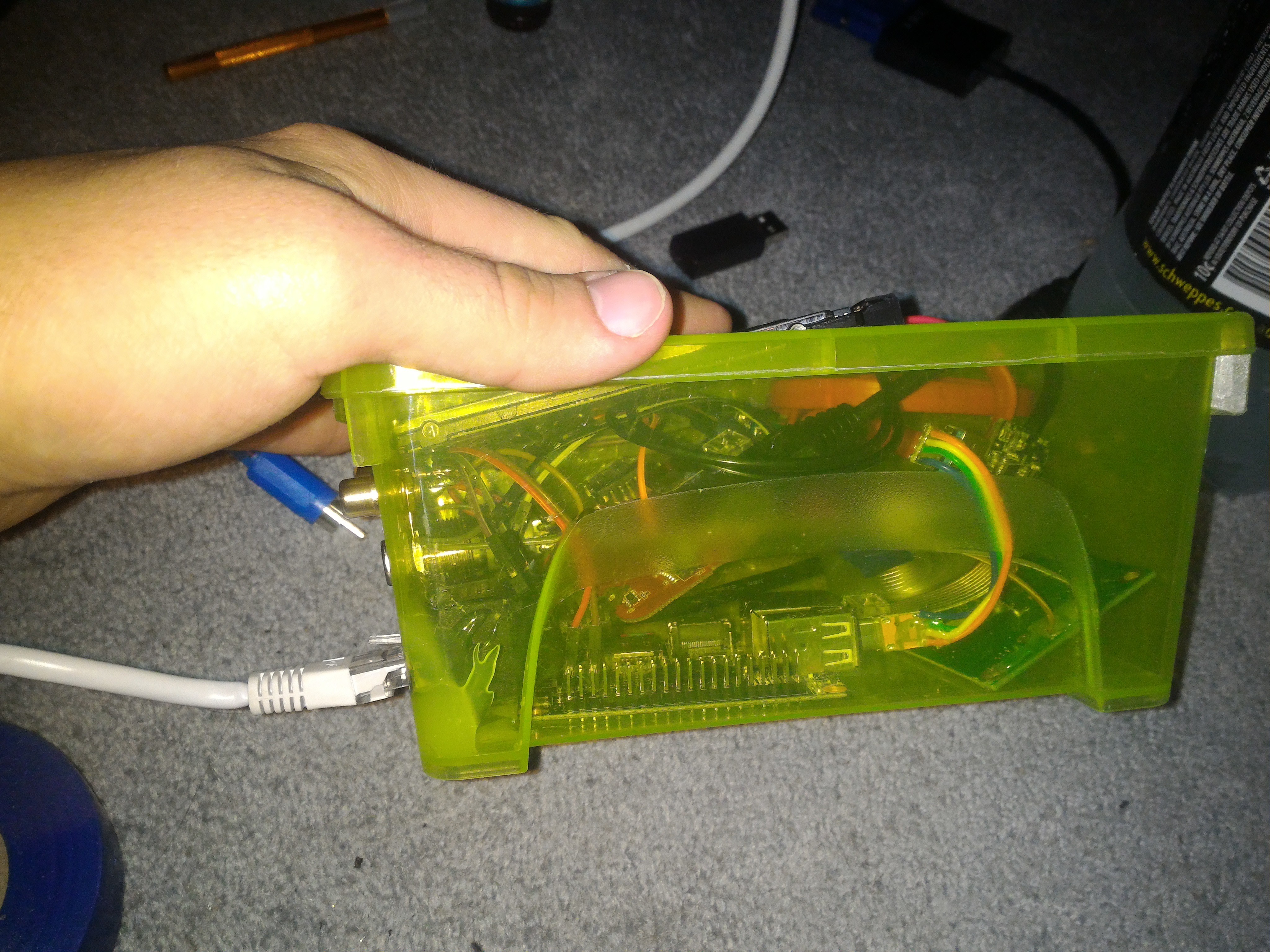
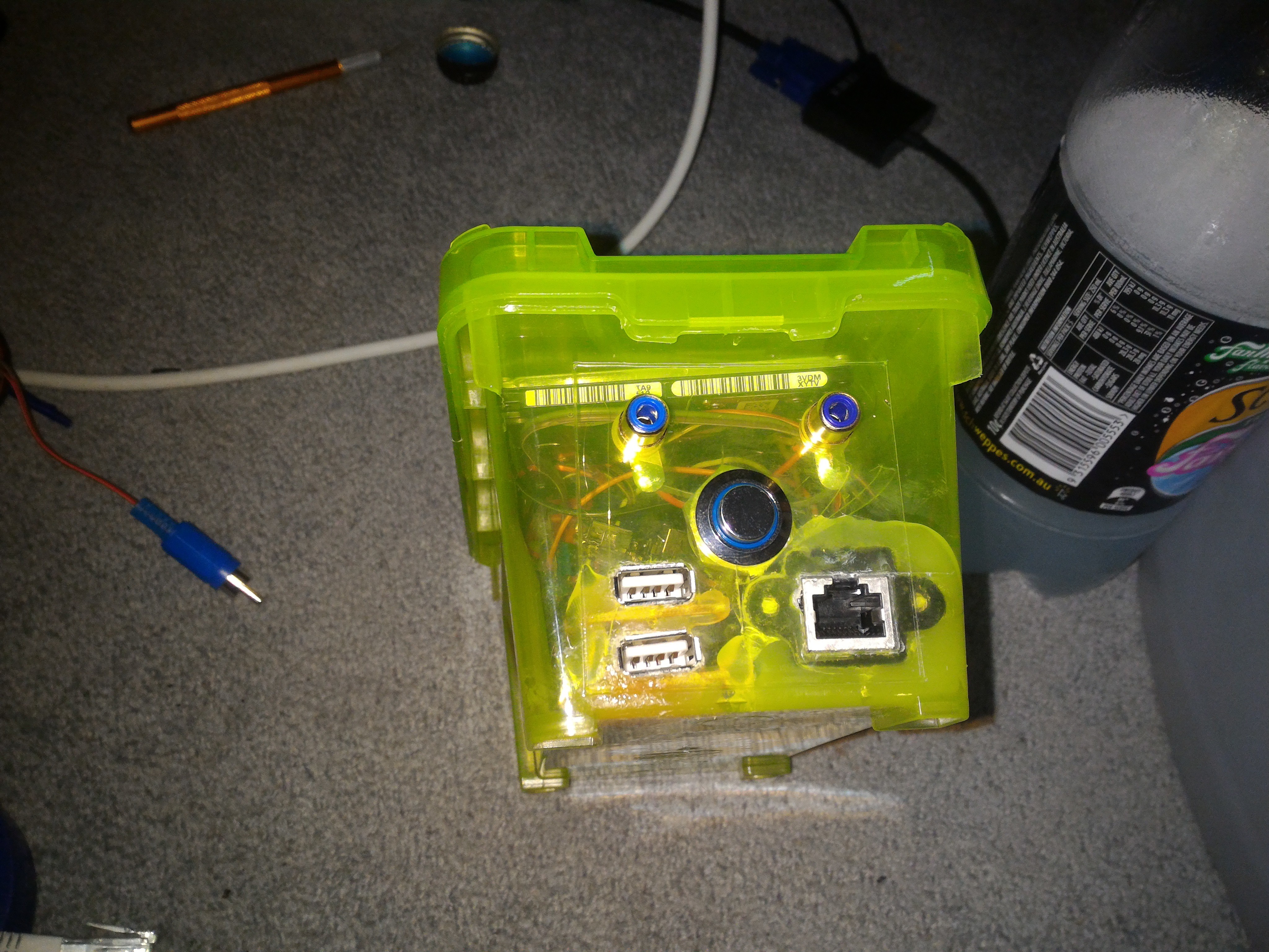
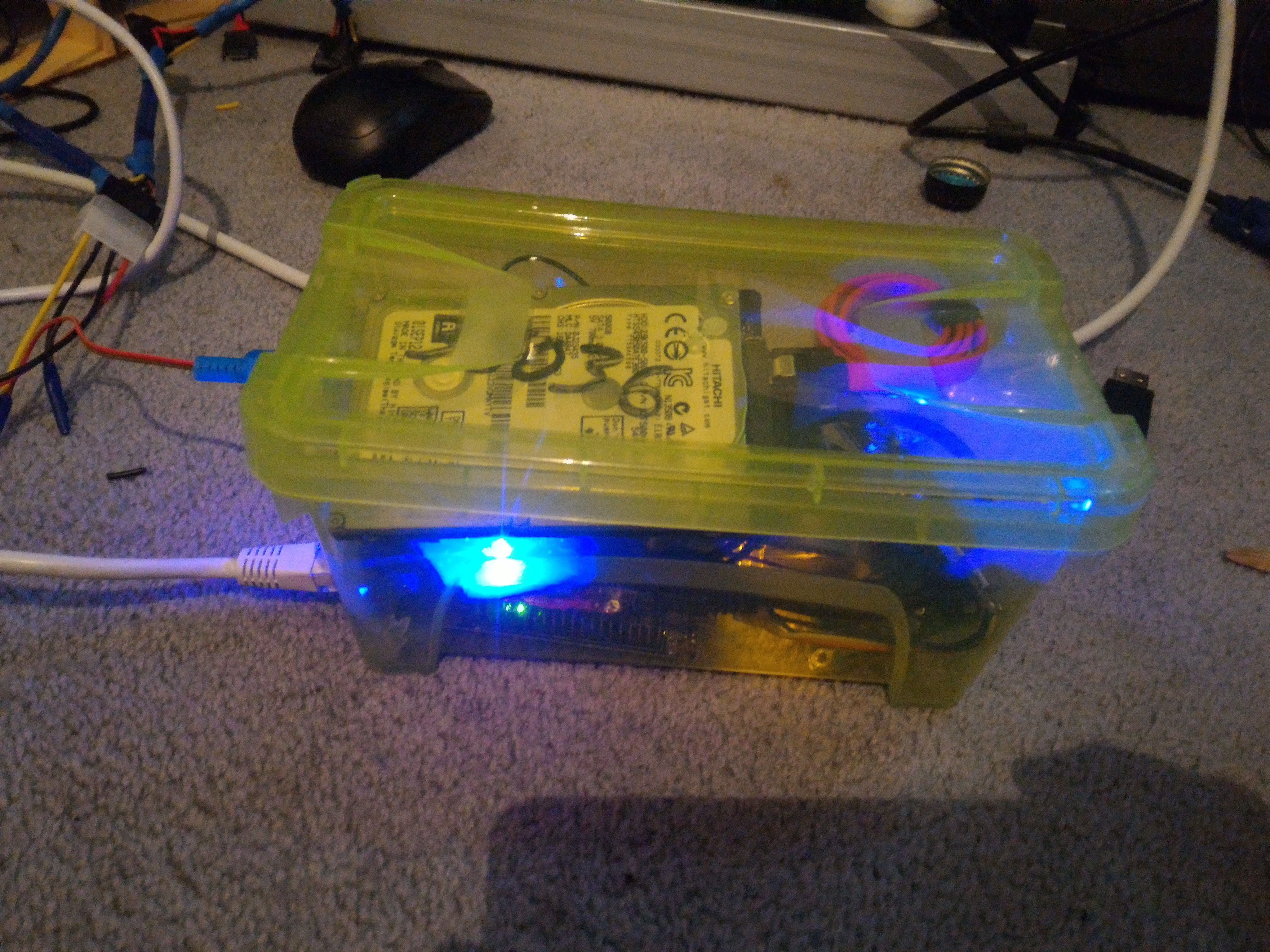
Done!
Whoops, forgot to plug it in.
At this point I turned it on ("it" kinda makes it sound like some collective abomination at this point), and I connected up to the access point, but the oppai was nowhere in sight.
Taken home for some serious diagnostics.
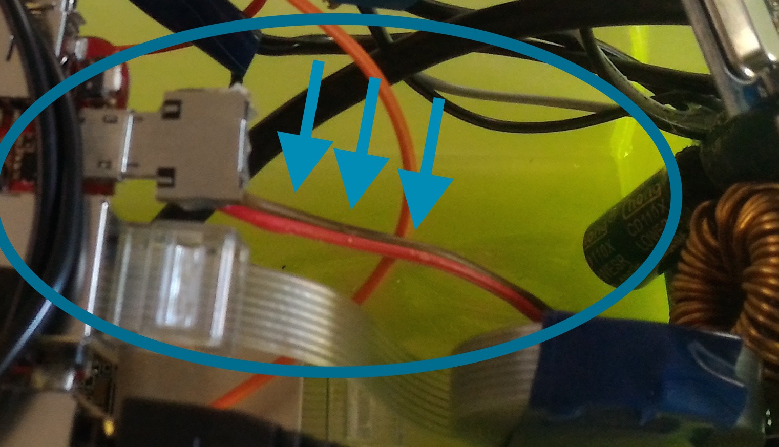
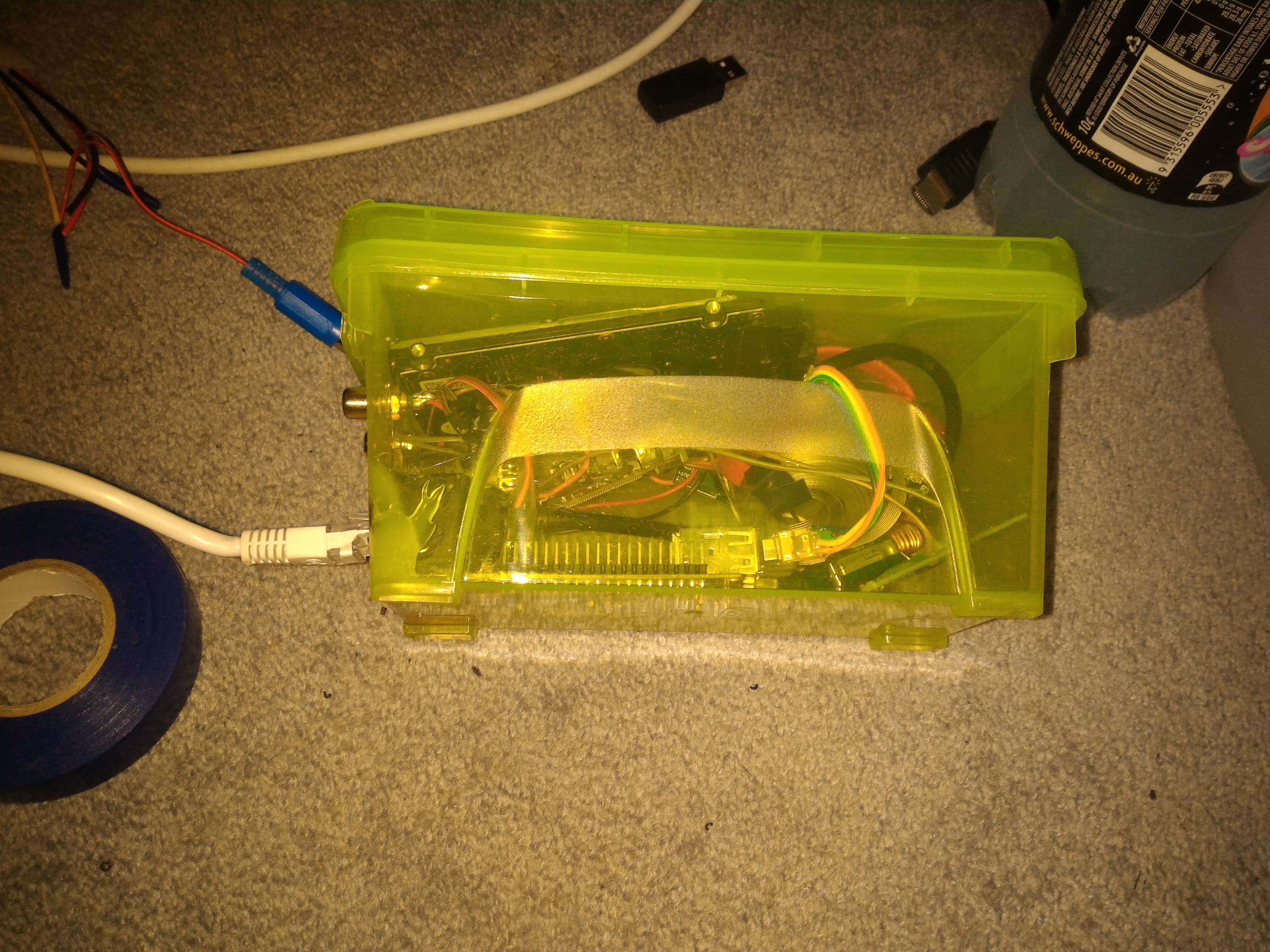
I checked every part piece by piece, and the flat ethernet cord seemed to be unhappy about being wrapped so tightly.
Tied it up not so tight, and all was well.
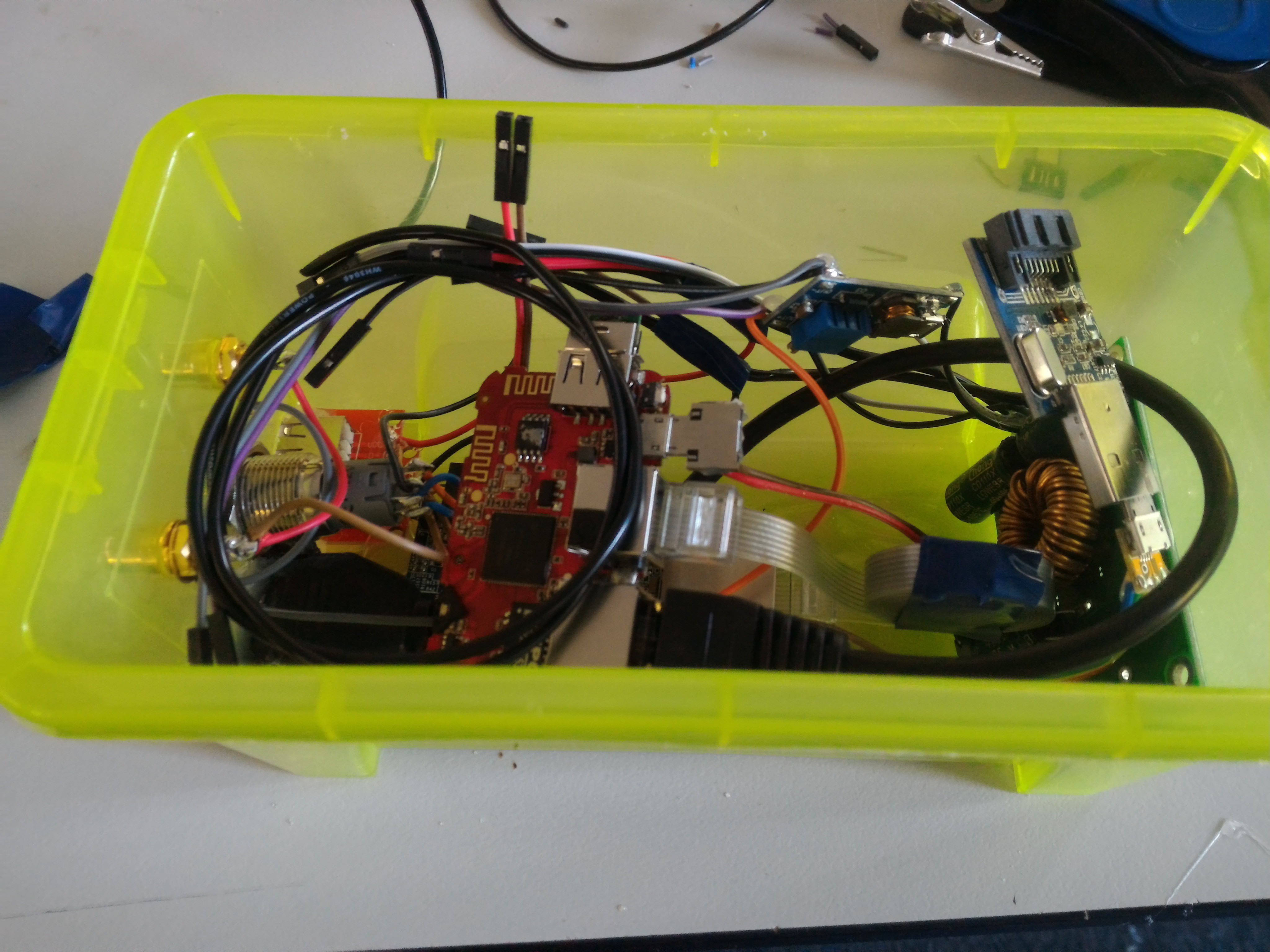
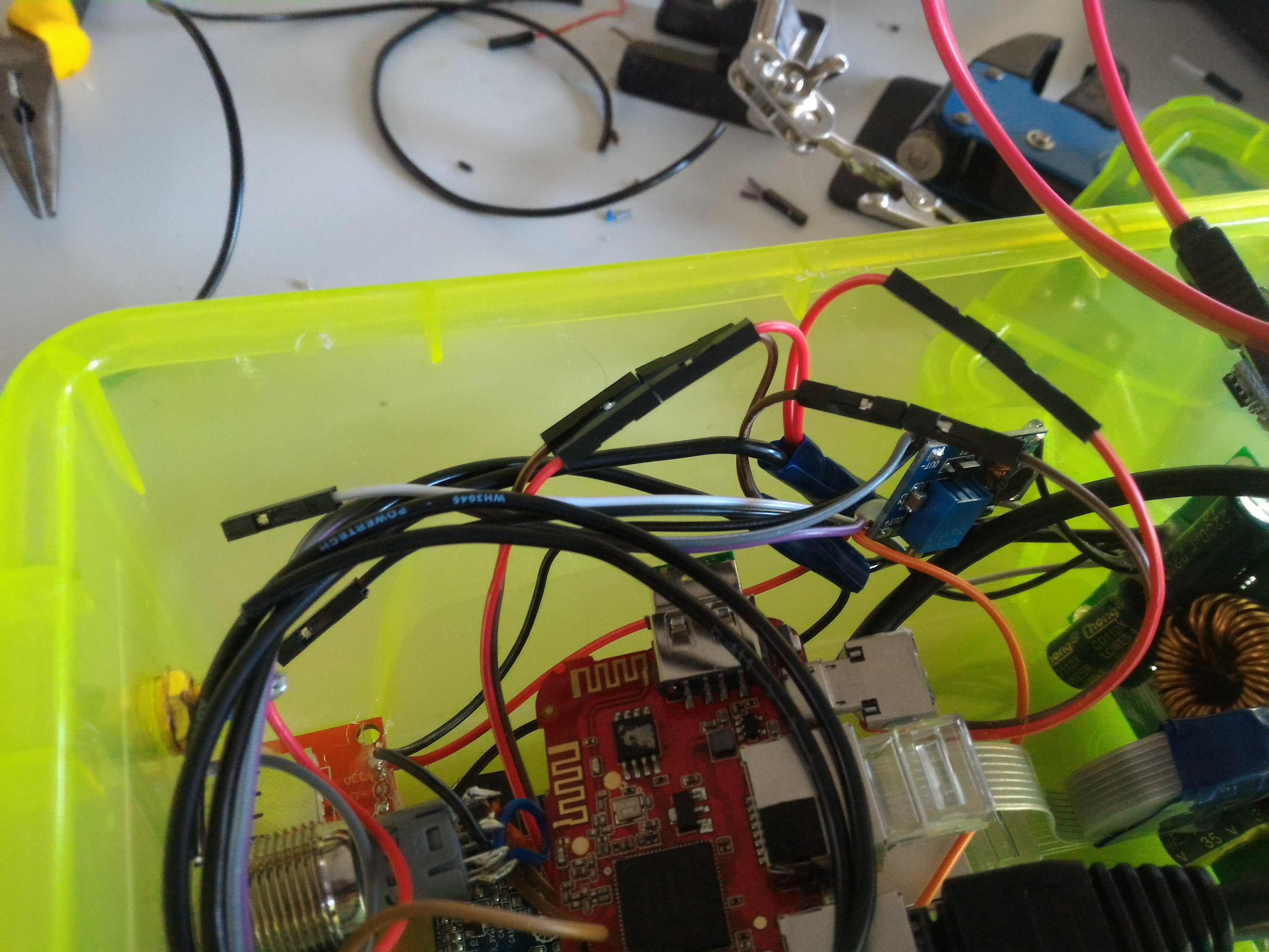
Commencing image dump.
All gooOH WHAT NOW?
 Lemme clean up that SATA cable then...
We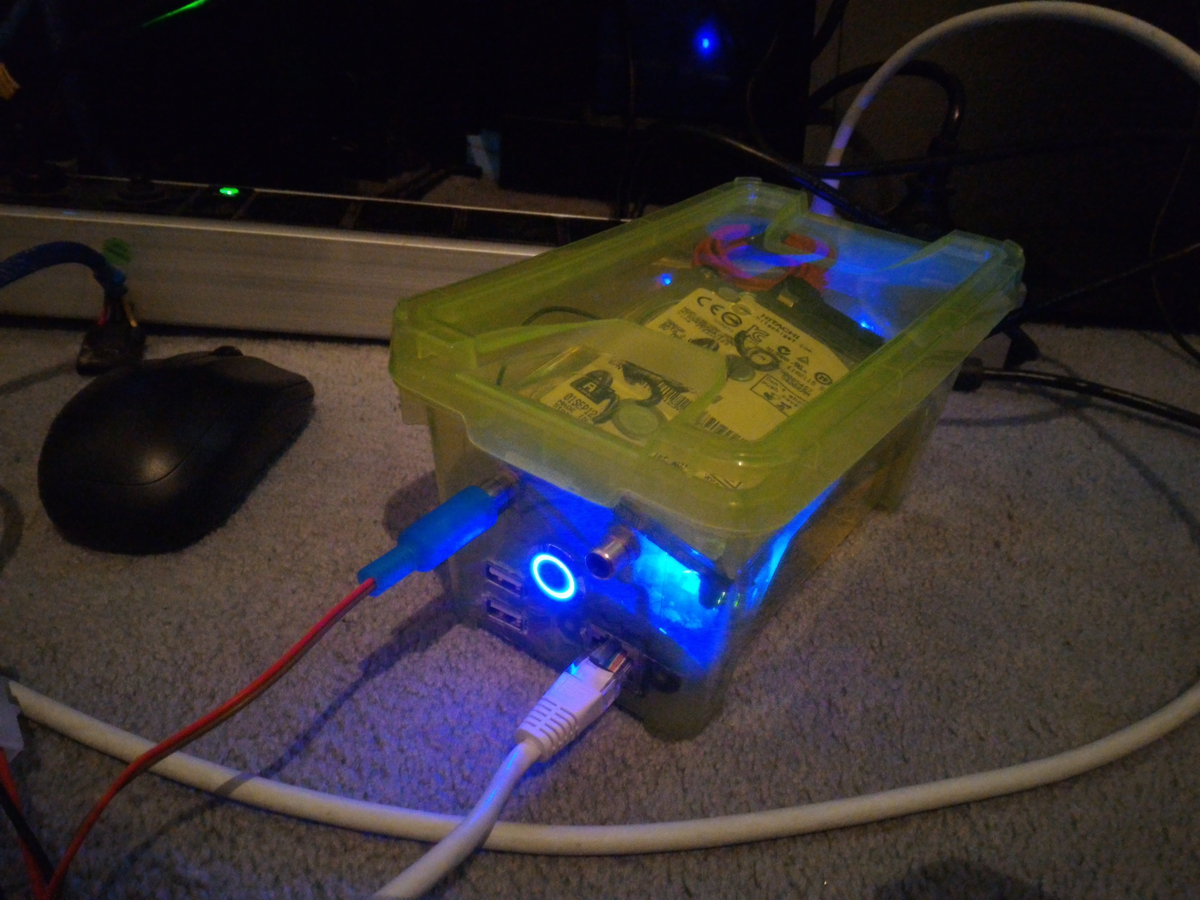 Are
Are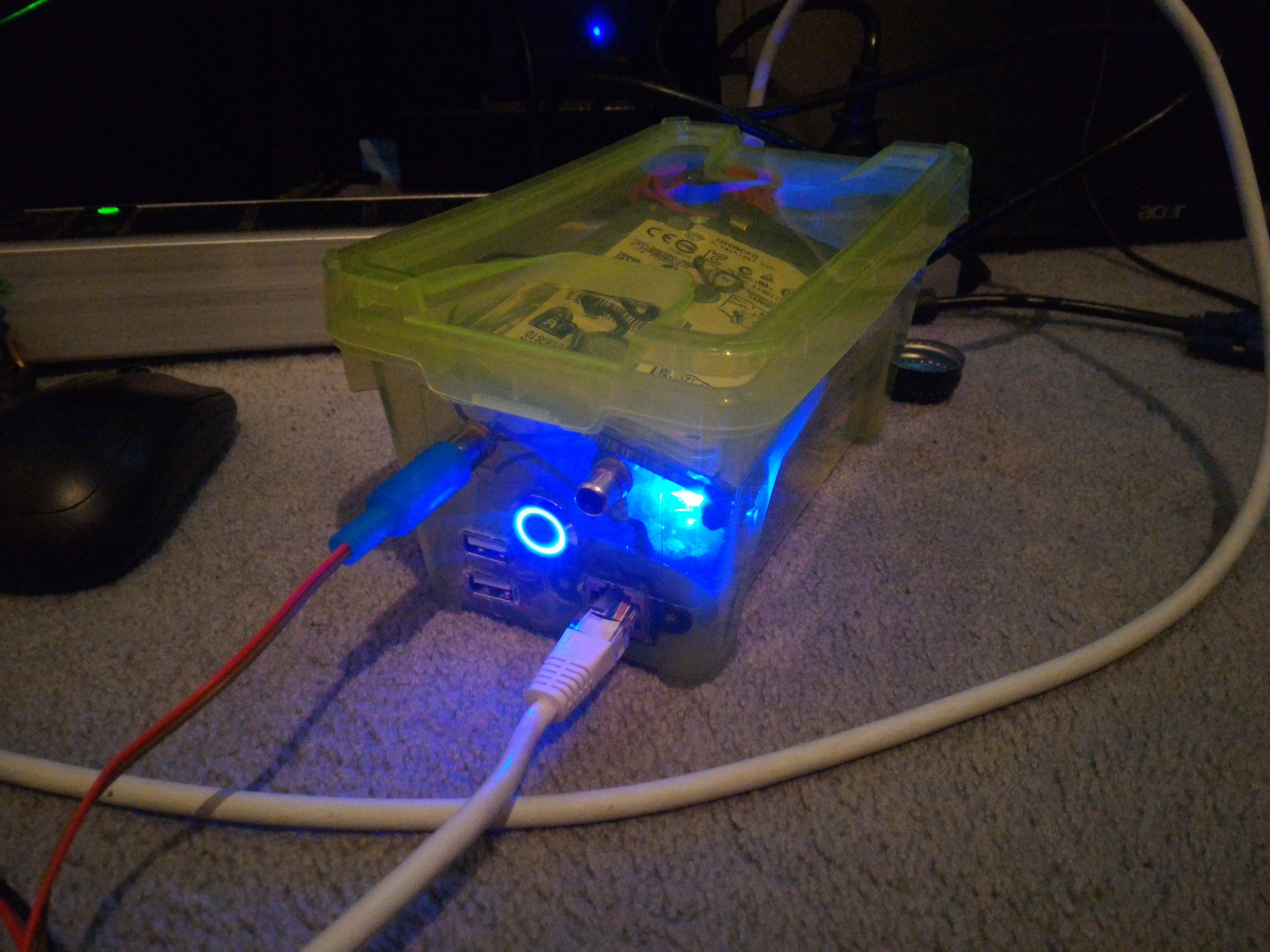
Done.
Discussions
Become a Hackaday.io Member
Create an account to leave a comment. Already have an account? Log In.