 Sandeep
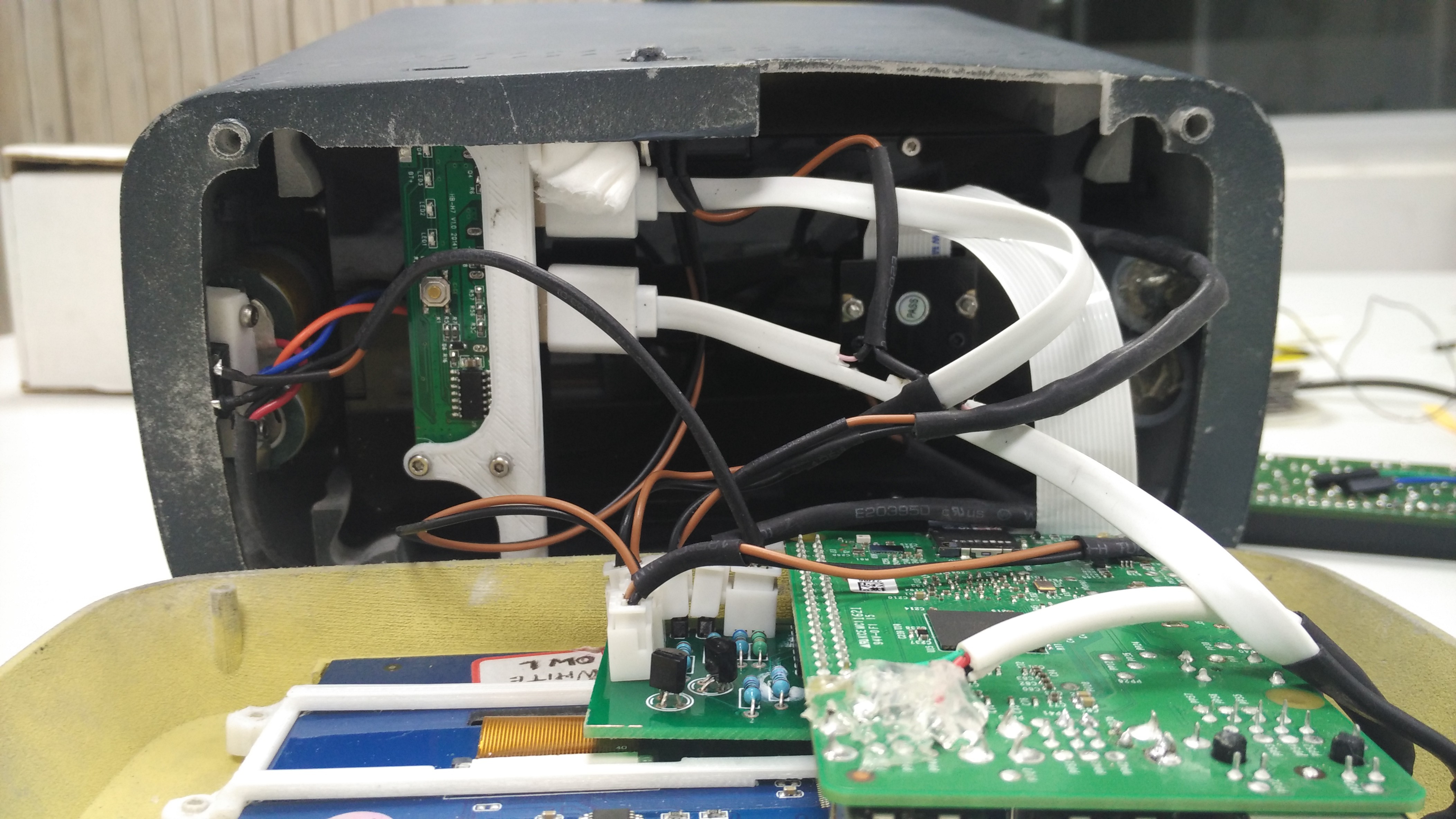
The messy wires inside the device can be taken care by decreasing the lengths of the wires. All the connectors should be standardized so they can be easily reproducible.
We can start with the PCB. The earlier PCB was used for prototyping. It has 8 slots for the multiple LED's for testing to get the proper illumination on the Retina. Now we know, we only need single LED to shine the Retina. So the extra slots can be removed and the PCB can be compressed.
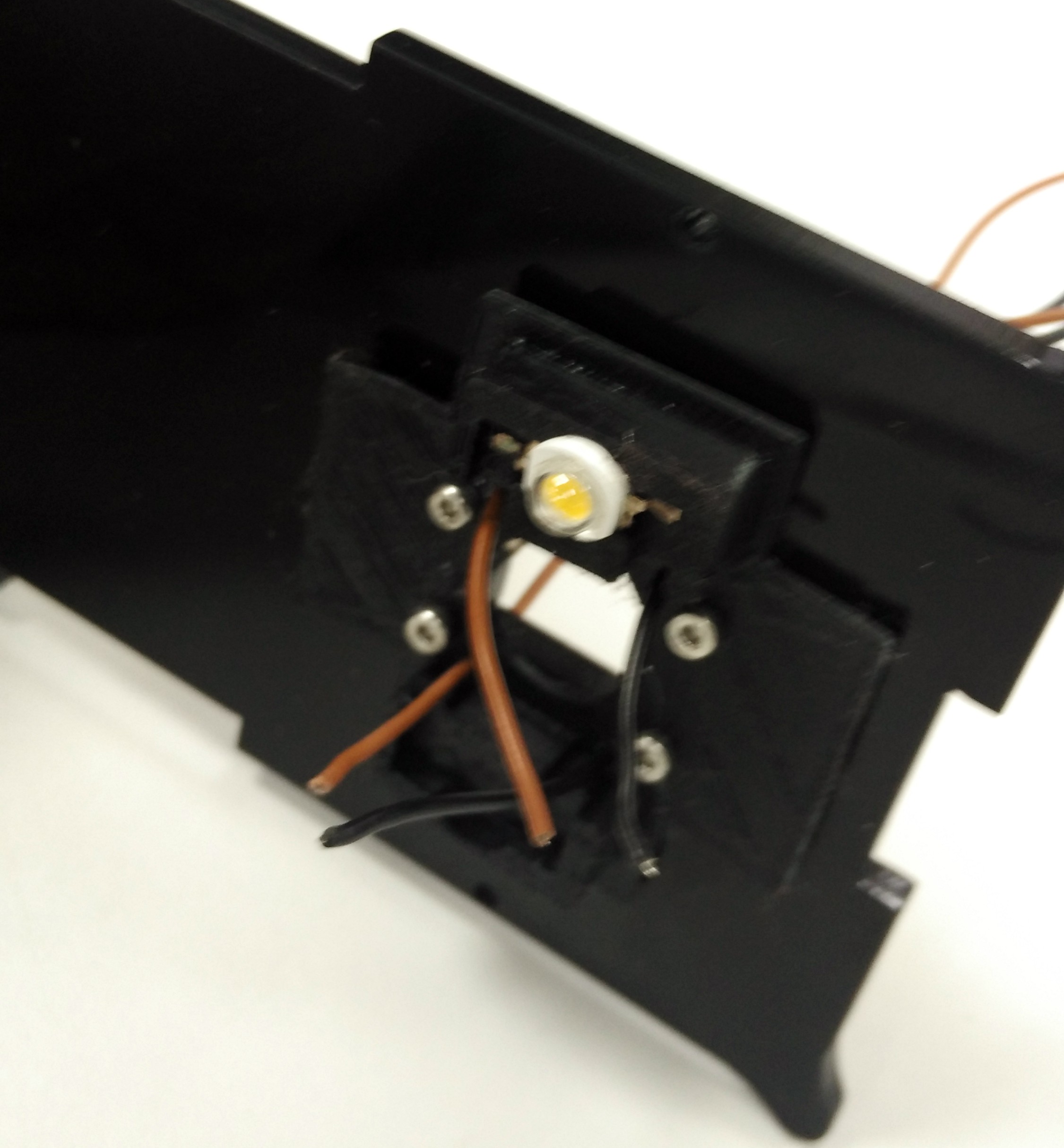
LED Placement
If you see the LED, it is placed on the top of the camera by which we are capturing the image of the left eye's Retina. If we need to get the same standard image on the right eye as well, then we need to place a LED on the bottom so that when the device flipped it comes on the top of the camera. Thus we can get standard images from both eyes.
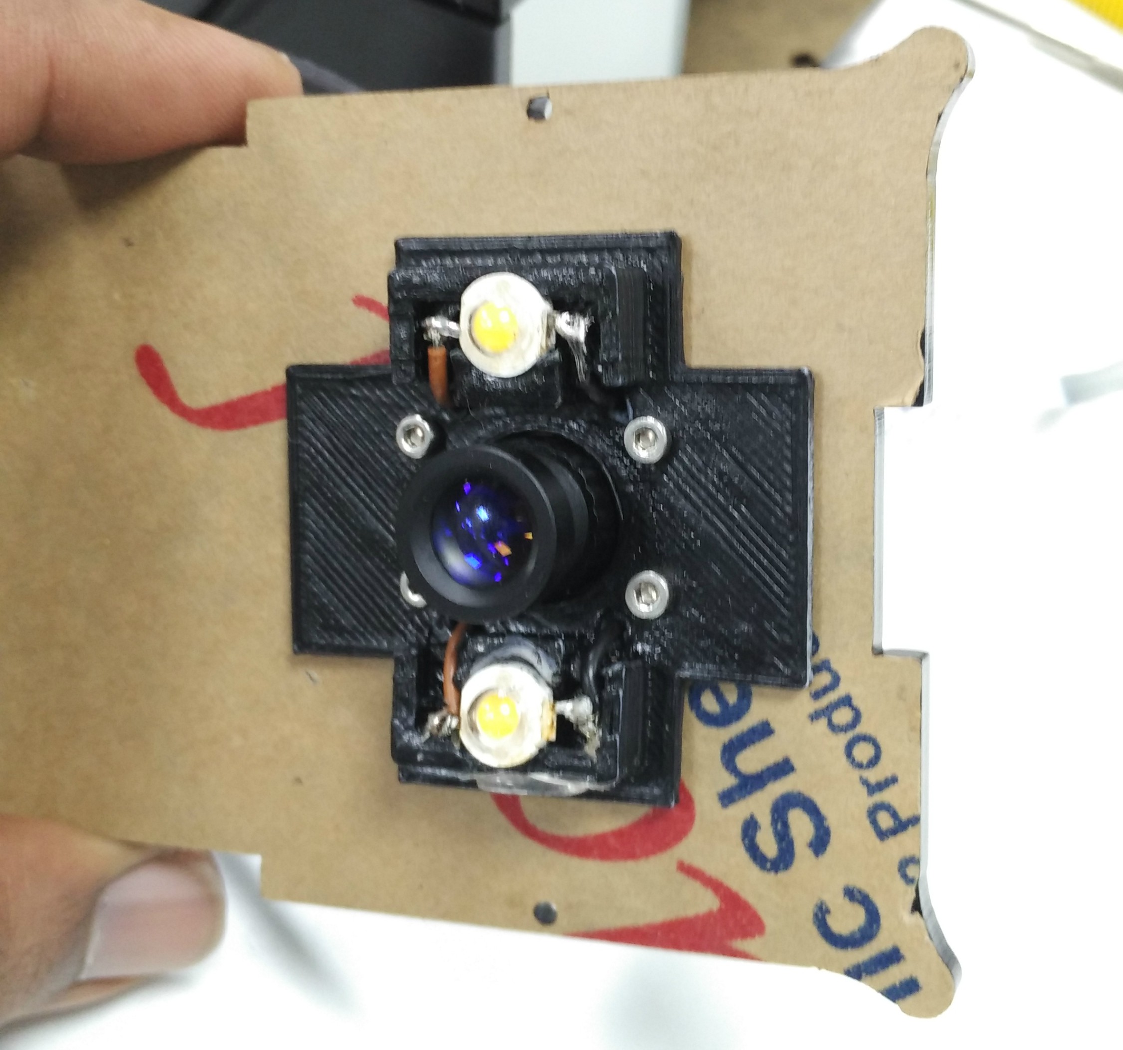
TWO LED's
So a new PCB with only 2 LED ports can be made.
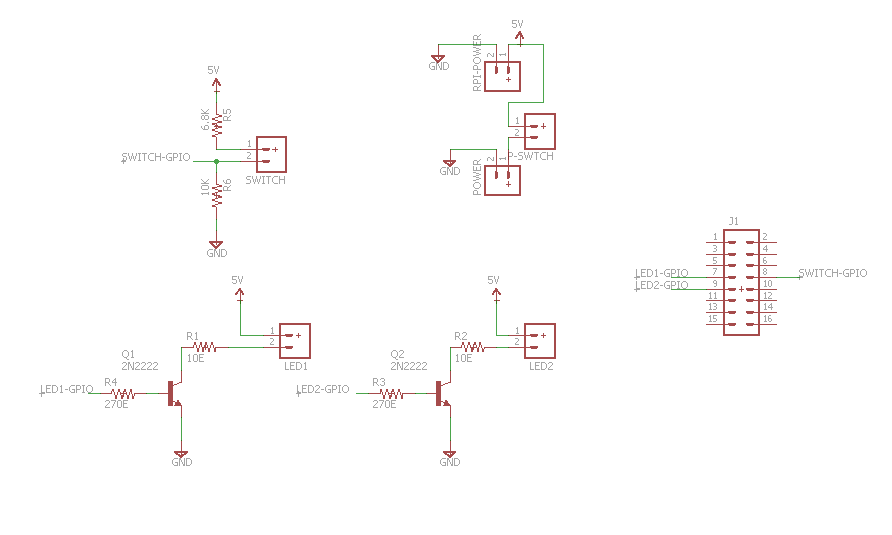
PCB Design
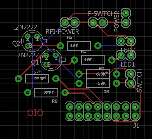
PCB Assembly

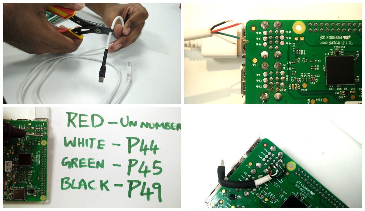
Touch cable on R-Pi
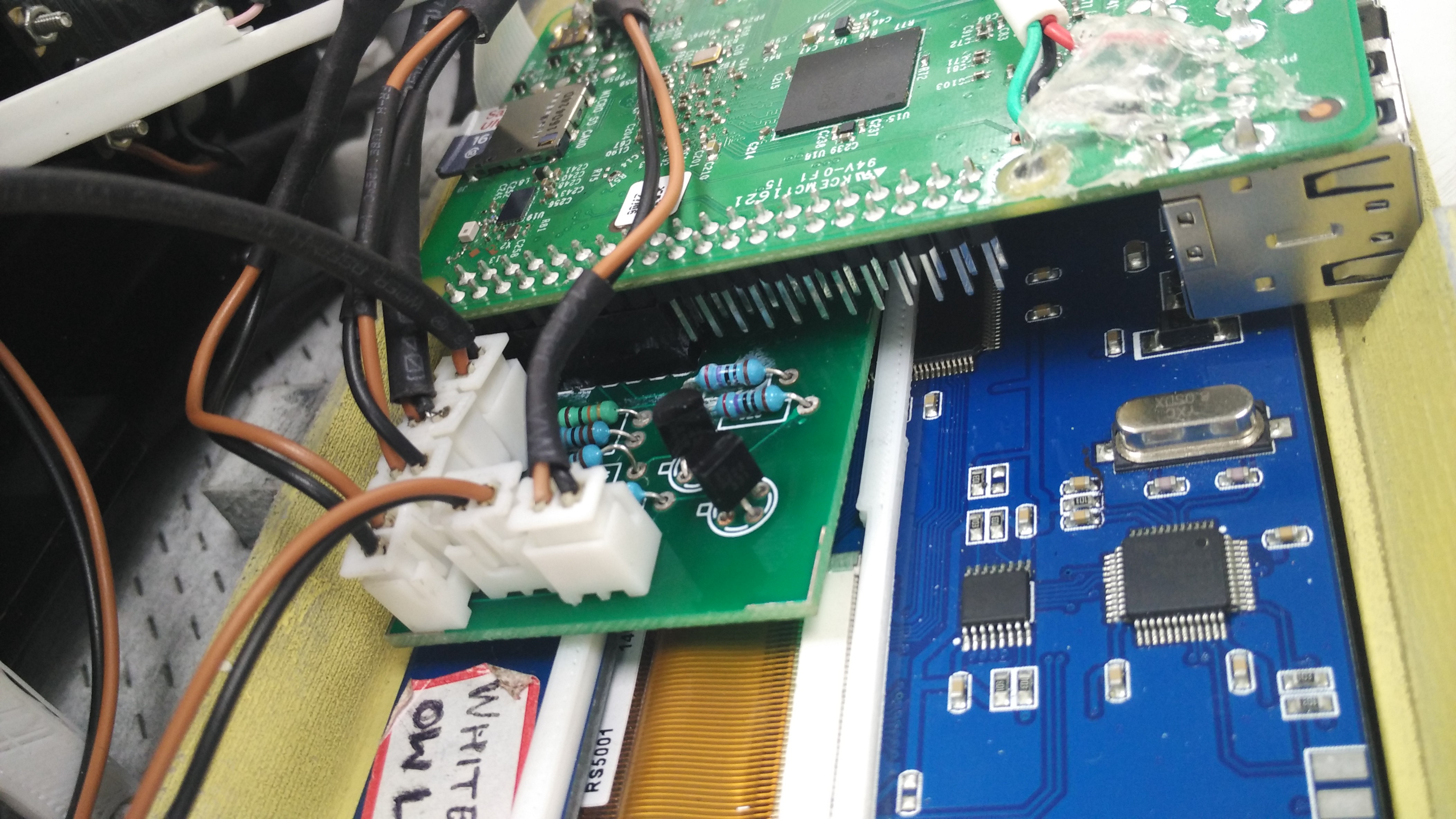
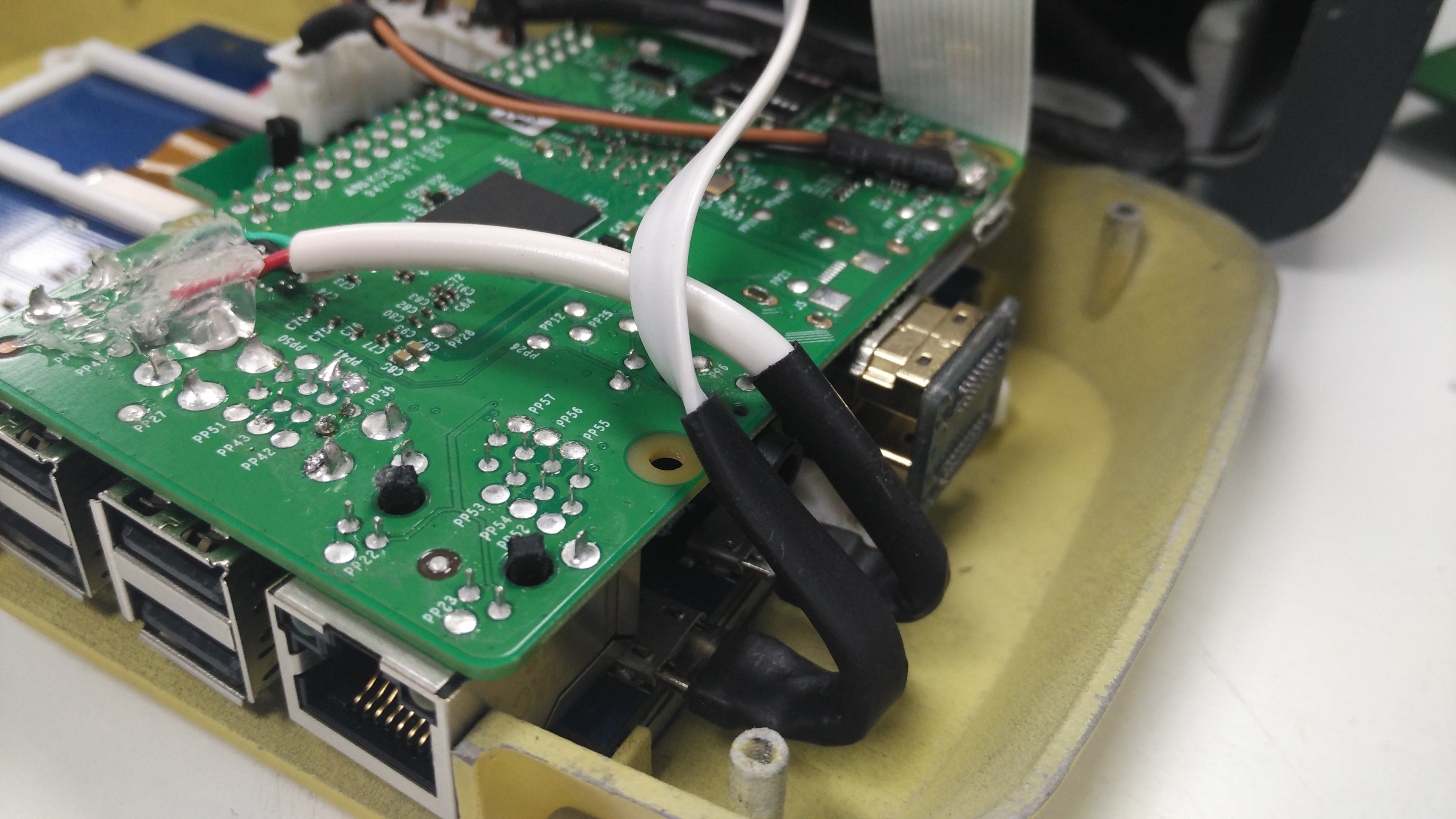
The cable for touch from one of the R-Pi USB ports to the screen can be by passed. By finding the corresponding solder connections for a USB port on the R-Pi we can solder the USB cable's wires directly to those points and decrease the length of the wire.
Power Input for R-Pi
The micro USB power input to the R-Pi can be by passed by soldering two terminals to the +/- on the R-Pi and connect them on the PCB

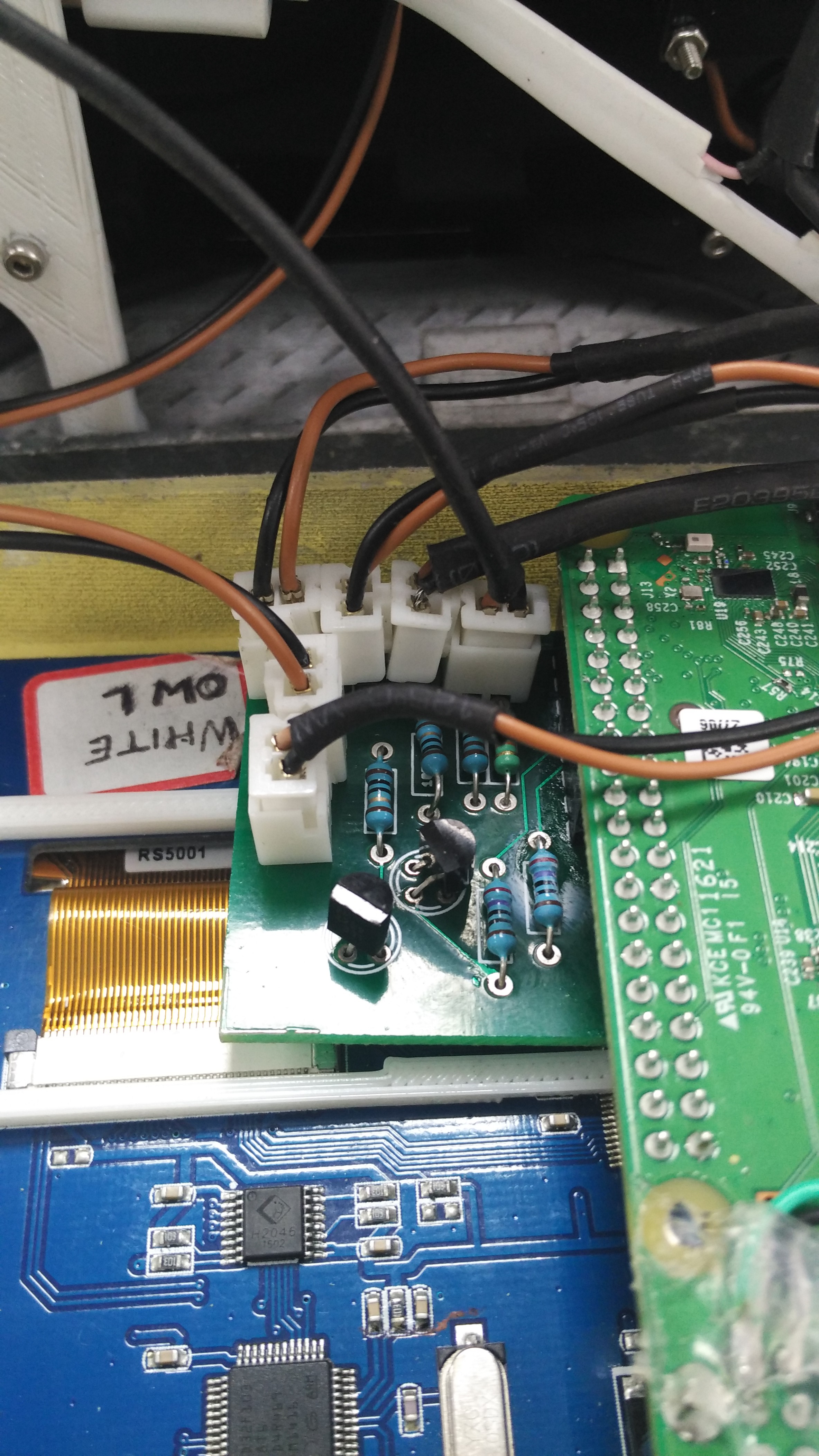
Power Cables from Power Bank
Power bank has 2 USB female ports. One is 2.0A and another 1.0A. The PCB need to drive the R-Pi and the LED's so 2.0A can be directed to PCB. Instead of desoldering the USB ports on the power bank PCB connect a 2 pin female connector to a USB cable (Soldering micro USB female to the PCB is time taking). This will connect the power bank PCB through USB and to the main PCB it acts as a power input terminal with a 2 pin connector.
LCD screen couldn't take sufficient power from the touch port. As a result the touch malfunctions once R-Pi starts accessing the camera. So we need another power source so that's why we are using the 1.0A for the Screen.
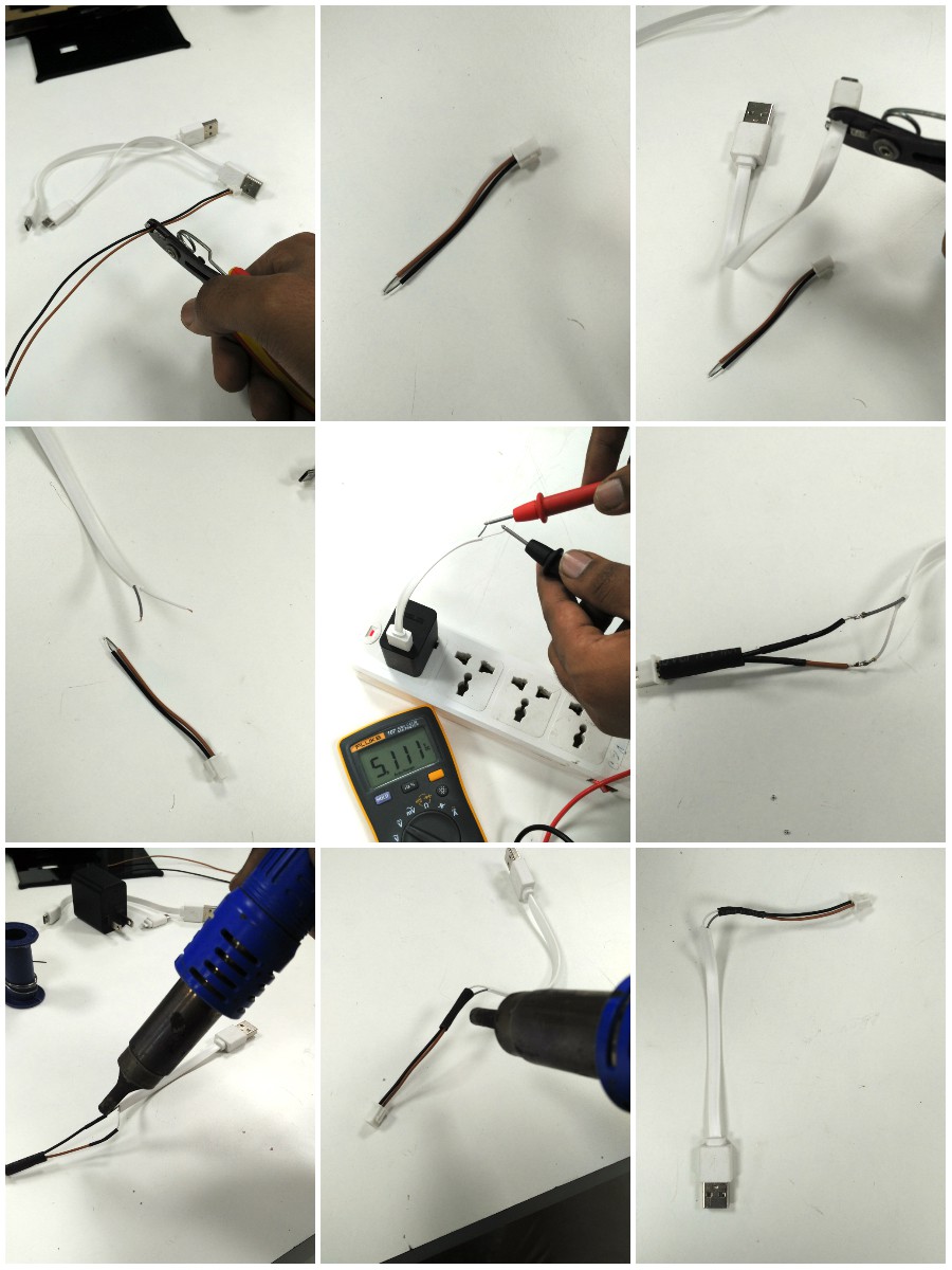
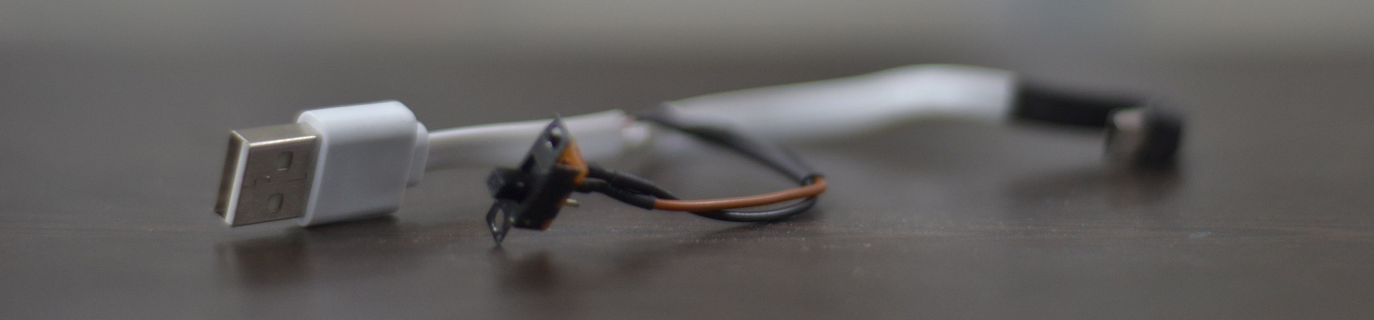
R-Pi and screen works on the same power source which is always on. For the R-Pi a switch slot is already given. Now the screen works on an independent power source which should be connected to a switch. So we need to add another switch to the screen power cord (Can add a 5V relay but it drains the power bank). Slit the cable and add a slide switch any one of the terminals.
The end of the cable is micro USB which is covered by a thick plastic layer. Because of this the cable can't bend and fit into the enclosure of front piece. So chip off the plastic with a knife and insulate it with a heat shrink.

Connectors Standardization
OUTPUT
Discussions
Become a Hackaday.io Member
Create an account to leave a comment. Already have an account? Log In.