 Kyle Gabriel
This build log will cover the construction of a hardware enclosure that has both a 7" touchsceen LCD display (1024x600 native) and switched outlets integrated into the unit.
Today's segment will cover installing the LCD, Raspberry Pi, power/signal distribution PCB construction, and sensor hookup. By the end of this session, we will have a Mycodo system reading and logging sensor measurements, but we won't yet have relays installed to actually have some fun controlling things.
The front of a 11"x11"x3.5" plastic enclosure was cut to accommodate the 7" LCD. The LCD was secured with screws to the back of the door. Because the actual glass screen was much larger than the viewing area, black tape was used to hide the edge of the screen by creating a frame around only the viewable area of the LCD.
The Raspberry Pi (RPi) was attached to the back of the LCD with the acrylic mounting plate from the LCD stand kit. I wanted all the RPi's connections to be contained to reduce wear from opening and closing the door it's mounted to. I chose to use an IDE cable to connect the RPi (on the inside door) to a breakout board mounted inside. This breakout board was then soldered to a breadboard-style PCB (the free ones I've received from Adafruit). This restricts all the chaos that can occur with numerous inputs and outputs, to the inside of the enclosure.
Raspbian Linux was flashed to a microSD card and booted in the Raspberry Pi, with the touchscreen and LCD display connected and ethernet cable plugged into the router. Login was achieved via SSH to set up wifi, get the LCD and touchscreen working, set the system to auto-login to desktop and start a web browser in full-screen mode, and install Mycodo.
The system was shut down and ethernet cable removed. A carbon dioxide (CO2) sensor (K-30) was connected to the Tx/Rx lines, an analog to digital converter (MCP3424), a liminosity (TSL2561), and a non-contact temperature sensor (TMP007) was connected to the I2C lines, and a PIR motion sensor was connected to a GPIO with a resistor. A soil moisture probe was connected to a channel of the analog to digital converter.
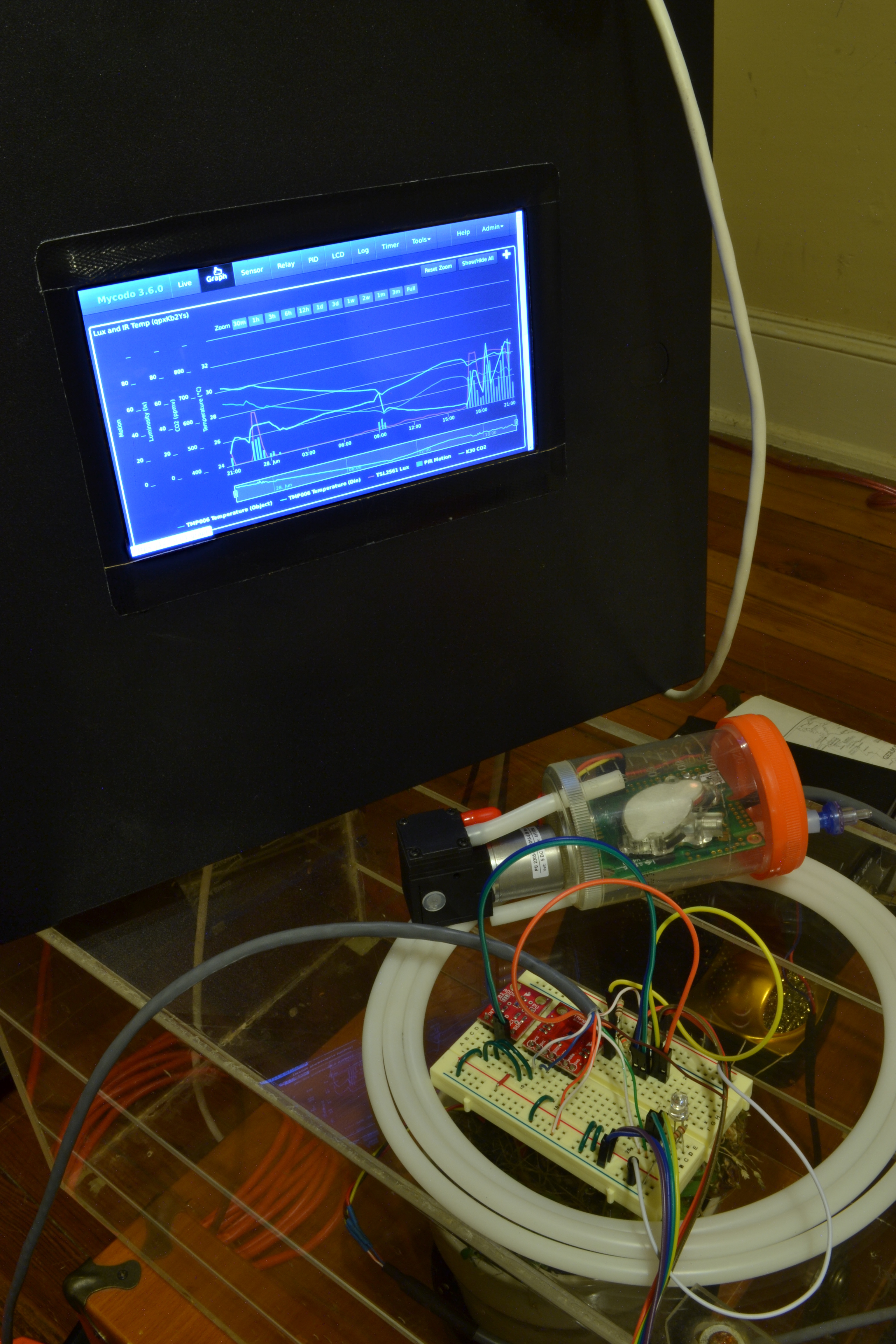
The RPi was powered and Mycodo was configured to use all the connected sensors. Here's the fruits of my labors for this session. Next session will see the addition of relays and we can begin controlling devices based on our sensor inputs
Note: The LCD is actually much better-looking than this photo depicts. I think the vastly-different color temperatures between the LCD and incandescent lighting was to blame, and I didn't care to try to correct it. More photos will come, but here's a nice end to the first actual build log for this particular system.
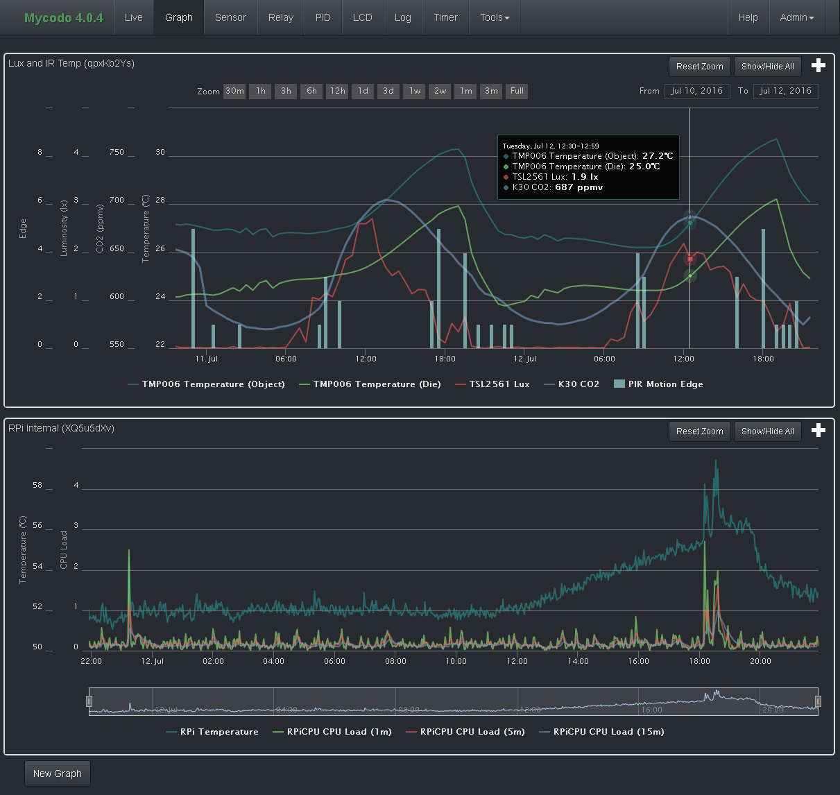
And below, a screenshot of the graph page of Mycodo, set up to display all the sensor data being logged on this system, on two graphs.
Discussions
Become a Hackaday.io Member
Create an account to leave a comment. Already have an account? Log In.