 Kevin Kadooka
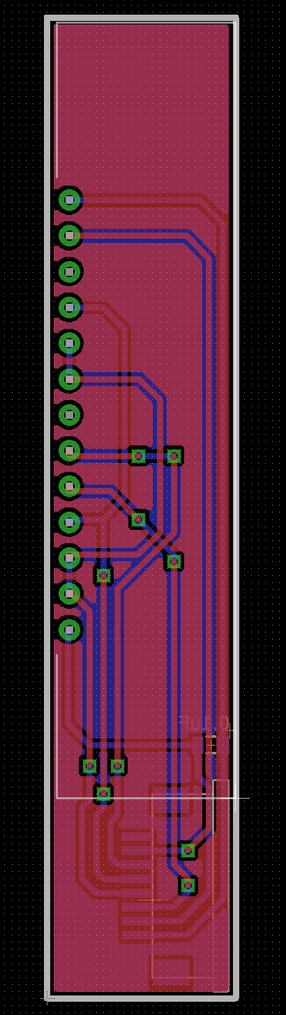
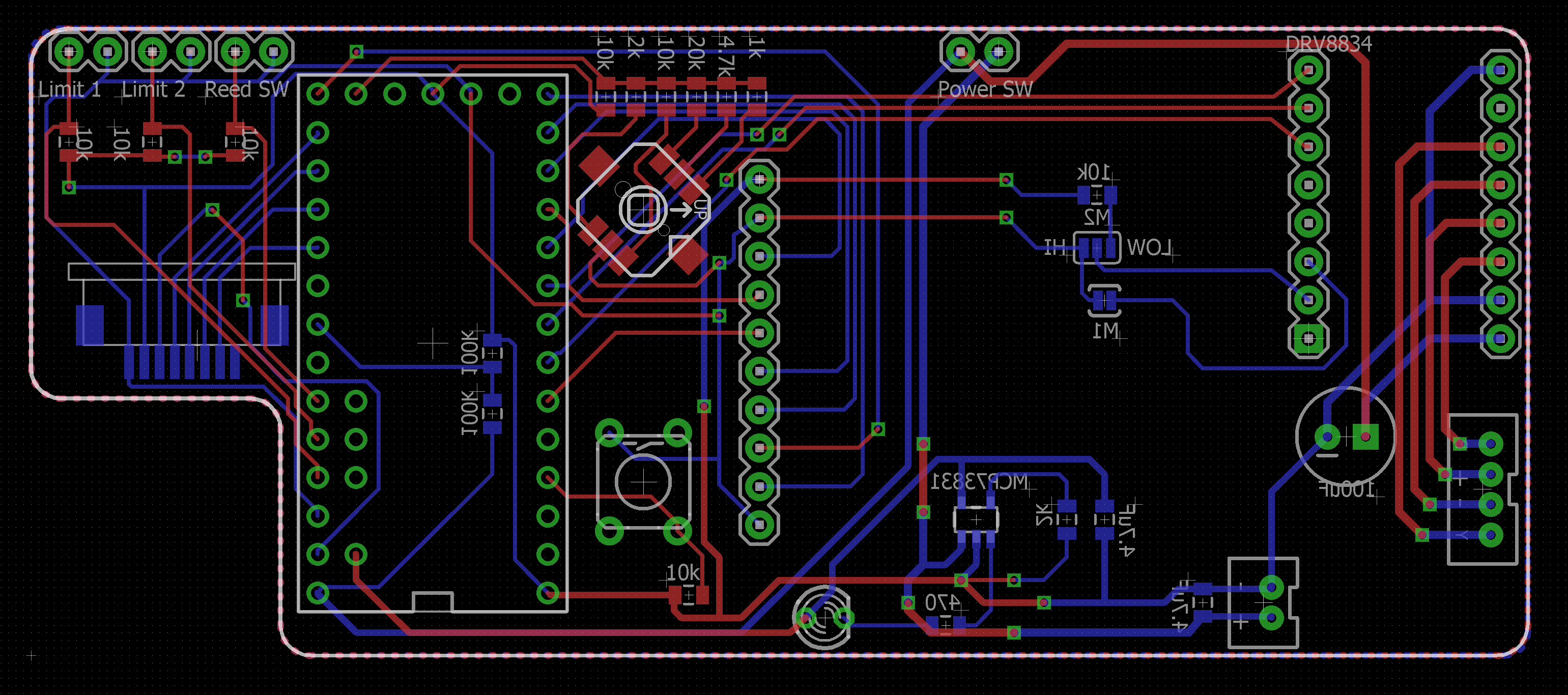
After a bit of idling, I got off my butt and did something. The two PCBs required for this project were ordered from Seeedstudio. Nothing too fancy, but here's what they'll look like (this was my first attempt at using EAGLE - don't judge me too harshly).
The sensor board holds the sensing array (TSL1406RS), a decoupling cap, and a FFC connector. Pretty simple. This part is what gets scanned across the image plane.
The main board holds everything else: Teensy 3.2, stepper driver, battery charger, TFT screen, etc, etc. The ground fill is hidden here for the sake of clarity.
After a week or so of having things on the breadboard, I'm pretty confident that it should work (fingers crossed!). Now, onto the next fun part - mechanical design of the camera itself! I've already shown more or less what the camera will look like, but I've had to add a bit of polish and make some renderings.
Front view:

Rear view, with the viewing cover closed. The black rectangle on the upper right is the TFT screen. There are navigational buttons below that, and on the right corner, there's a small door covering the micro-USB connector of the Teensy. That will be accessible for charging the battery, and programming. Above the TFT screen is another door for the uSD card, and the power switch.

Rear view, with the viewing cover open. It's hard to see here, but opening the viewing cover swings a piece of ground glass onto the image plane. This can be used for composing the image.

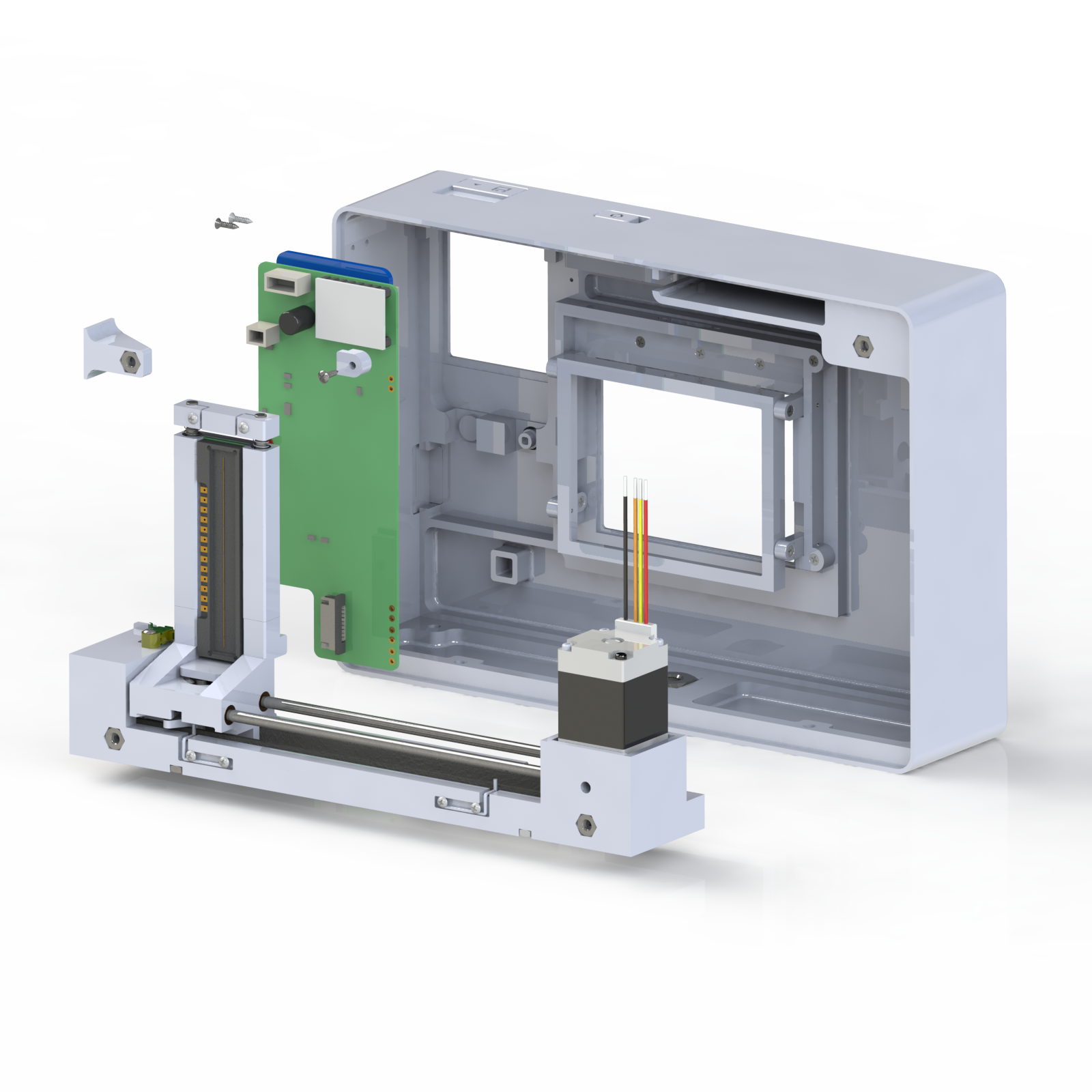
The earlier photos obfuscate the seam line, but the case is composed of a front and a rear portion. The rear portion really holds all of the goodies, and the front portion is a standoff for the lens.

Here's looking closer at the rear case and its contents. The main components are the main PCB, shown here populated with its various parts, and the image scanning stage. You may recognize the tiny NEMA 8 motor mounted on the right side of the stage - this is driving a timing belt which moves the image sensor.
One aspect that I'm pretty proud of is the system for image viewing. When the viewing cover is closed, the ground glass is swung out of the way of the image sensor.
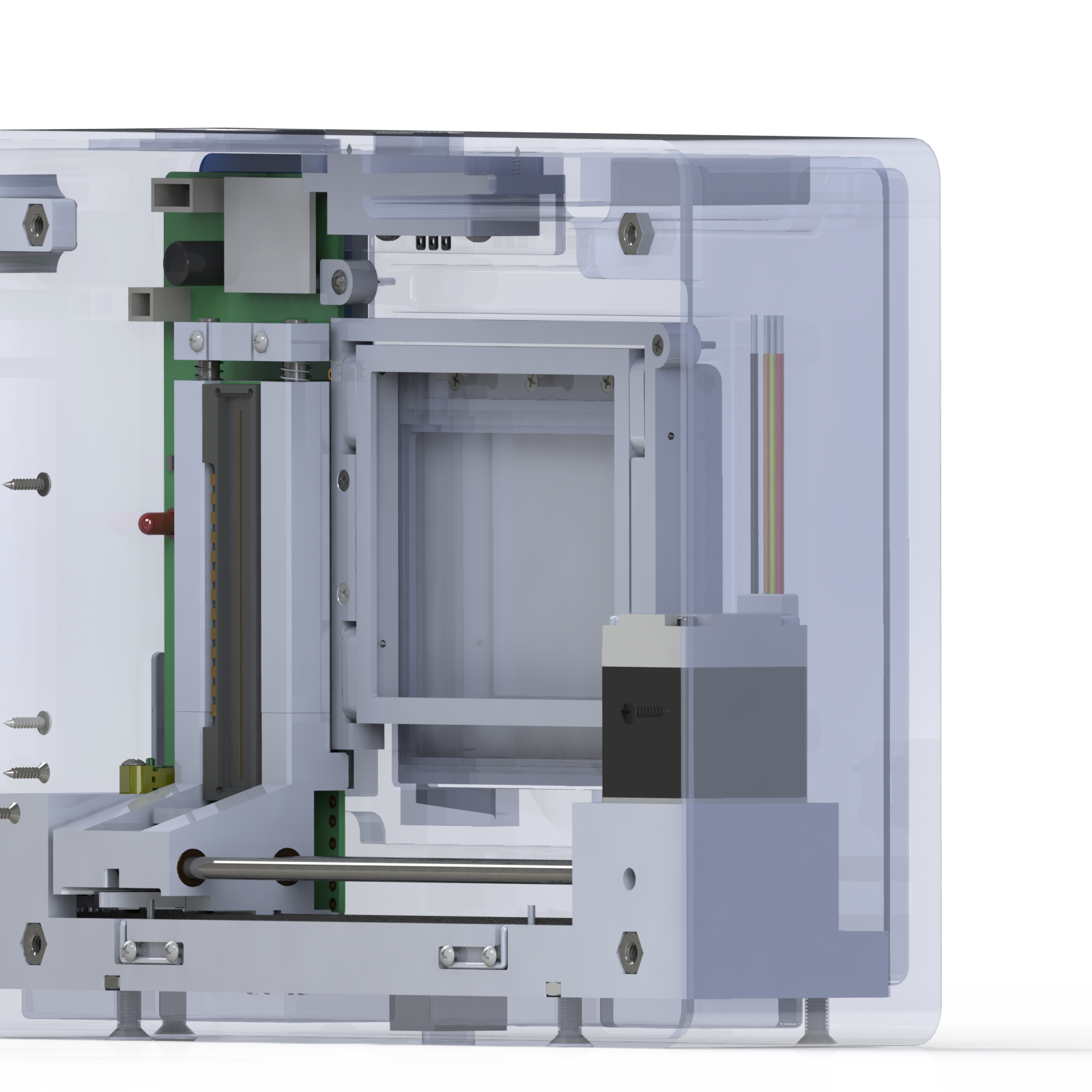
Then, when the viewing cover is fully open, the ground glass holder swings into the plane of the image, so that the image can be composed. Of course, there has to be some way to check that the viewing cover is closed before moving the image sensor (or else, it would crash - yikes). This will be done with a magnet and a reed switch (not visible here).

All in all, pretty simple. Most of the custom parts will be 3D printed by Shapeways in either White Strong & Flexible, or Metallic Plastic. I removed as much volume as possible to reduce the printing cost to about $250, which I think is pretty dang good (if I do say so myself).
Next time, I hope to post some video of the breadboarded system doing its thing, with the menu structure I've developed.
Discussions
Become a Hackaday.io Member
Create an account to leave a comment. Already have an account? Log In.