Etch-A-Whiteboard
Automated Precision Drawing for the Artistically Impaired
Nate Foss and Alex Hoganson
Automation and Robotics Research Lab
Thomas Jefferson High School for Science and Technology
2015-16
Table of Contents
Abstract 3
Introduction 4
Literature Review 5
Inspiration 5
Hardware Acquisition 5
Methodology and Results 6
Bill of Materials 6
Horizontal Axis 6
Vertical Axis 7
Pen Holder 7
Electronics 8
Code 8
Generating the Instruction File 8
Interpreting the Instruction File 9
Discussion 10
Problems Encountered 10
Broader Application 10
Conclusion 11
Final Comments 11
Resources 12
Appendices 13
- Holistic Visual Documentation 13
- Bill of Materials 14
- Hardware 15
- Electronics 21
G. Image Processing Code 22
H. Image Processing Results 25
I. Movement and Instruction File Reading 26
Abstract
Our project was designed in the context of aiding advanced, large-scale prototyping and drafting work. By creating a machine that can draw large-scale, real-world vectored images from any photograph, our research sought to enhance the artistic ‘skills’ of the average individual. We were inspired to create this drafting aid when we noticed the lack of such a helpful tool, and all the potential uses it could have. This automated drawing tool could revolutionize the classroom setting and change forever the way we make prototypes.
The key to successful implementation of this project was moving the pen around on the board exactly as we wished via the Raspberry Pi’s direction. Taking inspiration from 3D printers and laser cutters, we decided on the two rail system diagramed in figure C.1, with the addition of a pen holder to control if it drew when it moved or not. The two axes were horizontal, across the top of the whiteboard, and vertical, which moved across the board and moved the pen holder up and down it. The final product closely matches the diagram, and can be seen in figure C.2.
To accomplish this, the Etch-A-Whiteboard used sophisticated edge detection algorithms in conjunction with precise DC stepper motors. While constructing the Etch-A-Whiteboard, many problems were encountered and subsequently solved. Complications that were solved included unnecessarily heavy components, stepper motors with insufficient torque, large 3D printer tolerances, power supply problems, and analog linear actuator control mechanisms. However, the large time buffers built into the project during the design phase allowed these challenges to be overcome and still complete the Etch-A-Whiteboard on time.
The project terminated in a satisfactory state of functionality. The Etch-A-Whiteboard accurately renders instruction files to trace the edges of images with precise lines. Persistent problems included heat dissipation and logic voltage discrepancies.
Introduction
Our project was designed in the context of aiding advanced, large-scale prototyping and drafting work. By creating a machine that can draw large-scale, real-world vectored images from any photograph, our research sought to enhance the artistic ‘skills’ of the average individual. We were inspired to create this drafting aid when we noticed the lack of such a helpful tool, and all the potential uses it could have. This automated drawing tool could revolutionize the classroom setting and change forever the way we make prototypes.
Applications for this technology are many and varied. Its potential use in the classroom cannot be overstated. For example, envision an electronics professor who draws a circuitry diagram for his students. Although the diagram is well-made and understandable, it’s hand-drawn, and impossible for all his students to see at once. He could take a photo, and project it for his classroom- but that leaves his diagram unmalleable and static. But with such an automated drawing machine, he could perfectly reproduce that diagram on the whiteboard and chalkboard, yet still leave it open to editing, allowing everyone to study and learn optimally.
Similarly, consider a photo or diagram that’s simply too complicated for a human to reproduce accurately and efficiently. An automated drawing machine would be able to sketch images too tedious or too difficult for a human to, and perform this task reliably every time. Naturally, this accuracy and efficiency leads to potential uses in manufacturing. It’s very feasible to imagine automated drawing machines as giant poster-makers or blueprint producers: simply tape a sheet of paper to the surface and draw an image. Making large scale posters or blueprints normally requires access to prohibitively expensive gigantic printers only available to massive conglomerates. Automated drawing machines could complete the same task for a fraction of the cost.
Our research focused on creating a working prototype of this device. Dubbed the ‘Etch-A-Whiteboard’, it would represent the early iteration of such an automated drawing machine. Our final goal for the project was to have it be capable of three distinct goals.
First, it would be able to translate a picture, such as a JPEG or PNG, into an instruction file that a Raspberry Pi could execute. Second, the Pi Pi would be able to execute the instruction files to drive two stepper motors and move the pen holder in two axes, while the pen holder had a pair of linear actuators that would enable the pen to be either up or down. Third, these two systems would be accurate enough for the Etch-A-Whiteboard to be able to draw images that were not only accurate and recognizable, but that also looked good. This third goal would require careful planning, engineering, and construction to accomplish.
One of the largest limitations on the Etch-A-Whiteboard is it’s lack of predecessors. Because we are creating the first ever large-scale automated prototyping and drawing machine, there exists little work, research, or parts designed for what we tried to accomplish. Many of the problems we had seemed to be unique to us alone, and solutions were seldom straightforward.
Literature Review
As our project was designed as a unique innovation, there was no predecessing literature relevant to our work. Much of the literature we examined took the form of datasheets, coding websites, and online forums. Of these, we found McMaster-Carr, SparkFun Electronics, and the Python Software Foundation to be most helpful. Information from these sites was almost always accurate, well-written, and easy to find. On the other hand, Firgelli Technologies had the least helpful literature, and we had to go to an external, third party website to even find the type of linear actuator we were operating.
InspirationNeither of us are very good at drawing. We noticed an unused whiteboard in the back of the room and thought that maybe we could make something that could draw for us. From there, after our research showed that no devices like this existed, we started thinking of all the potential uses for an automated prototyping machine, and the Etch-A-Whiteboard was born.
Hardware AcquisitionAs much of the project was custom made, many parts were made, not purchased. For those that were, we mainly used three websites. From McMaster-Carr, a manufacturing and engineering site, we purchased timing belts and aluminum pulleys. From Adafruit, an electronics site, we acquired the Raspberry Pi and from Newegg, another electronics site, we bought two H-Bridges. Finally, from Phidgets, we purchased two magnetically actuated stepper motors. Other hardware, such as steel rods or transistors, were requisitioned from supply bins found in the Robotics, Electronics and Prototyping labs.
Methodology and Results
The key to successful implementation of this project was moving the pen around on the board exactly as we wished via the Raspberry Pi’s direction. Taking inspiration from 3D printers and laser cutters, we decided on the two rail system diagramed in figure C.1, with the addition of a pen holder to control if it drew when it moved or not. The two axes were horizontal, across the top of the whiteboard, and vertical, which moved across the board and moved the pen holder up and down it. The final product closely matches the diagram, and can be seen in figure C.2.
Bill of MaterialsThe complete Bill of Materials can be found in tabular format in Appendix B. This Bill of Materials is divided by system, with Electronics, Frame, and Axes all having their own material allocations. Many system components, especially those that were 3-D printed, laser-cut, or otherwise handcrafted are represented solely by the raw materials it took to design them.
Horizontal AxisThe silver trough seen in figure C.3 in which the wheels are contained runs all along the top of the whiteboard. It was made from two aluminum angles held at a fixed distance apart by the Vex parts bent into a U shape around them (seen in figure C.3). The angles and Vex Us were then securely attached to the frame with the sheet metal screws visible in figure C.3. Those screws were also used to hold a series of scrap plastic tubes in place. These tubes were discovered by chance to have exactly the width of space between the wheels in figure C.3, and were thus used as a rail to keep the wheels in line. This was necessary due to the extra space in our aluminum trough which allowed the wheels to slide around too much.
The green part seen in figures C.3 and C.4 is what connects the horizontal axis to the vertical axis and allows the vertical axis to move at all. It grips the bar which is the vertical axis by tightening bolts through the three holes seen in figure C.4, letting us precisely adjust the height of the bar. On the other side, it hold three little Vex quad-wheels with a custom printed insert to hold them in place. This part and its wheels alone support the weight of the entire vertical system.
Despite its weight and inertia, the vertical axis and the part holding it slide quite easily in the rail. The system is moved by a single belt, seen in figure C.3 attached by a red 3D printed piece. This belt loops over a pulley at either end, one which spins freely and one which has a gear on its axle driven by a stepper motor below, as depicted in figure C.5.
Vertical AxisThe vertical axis, as seen in figure C.2, consists generally of a long aluminum pole with a pulley at each end, a belt running between them attached to the pen holder, and a stepper motor attached to one of the pulleys. The pulleys both spin freely on their ⅜” axles with bushings through the pole. The top pulley has a stepper motor attached coaxially in the back, as seen in figure C.6. A hole was drilled into the center and side of a ⅜” axle such that the stepper motor could fit inside and a set screw could be used to hold it in place. One delrin plate was screwed into the pole and the other was screwed into the stepper motor, then they were attached together at a fixed length using the spacers shown in figure C.7. The battery pack and H-Bridge module sat on top of the wheels and will be described in more detail below.
At the bottom of the vertical axis was a freely spinning pulley and another wheel-holding part (seen in figures C.8 and C.9) to rest on the bottom rail, support some of the weight, and prevent too much swinging. It had to have a hole through it for the axle, and an additional indent to accommodate for the bushing. In the end, the wheels were removed so that the blue plastic piece in figure C.8 would instead merely rest up against the bottom of the board. This choice was made because we found that having the wheels touching the bottom rail made the bar move less smoothly after all.
Pen HolderAt its core, the pen holder was comprised of two custom-made 3-D printed parts. These two parts were designed to enable smooth and fluid motion up and down the Y axis, and enable the raising and lowering of the pen.
The first 3-D printed part was designed to slide smoothly up and down the Y axis. As seen in figure C.10, a square cutout allows Delrin plates to be inserted between the plastic part and the metal axis. This helped decrease the amount of friction between the pen holder and the Y axis due to Delrin’s non-binding nature. Additionally, this part has space to hold two linear actuators, one on either side of a hole through which the Expo marker can move freely. These linear actuators are fixed to the plastic through use of screws and bolts. On the side of this part nearest to the Y-Axis were designed several teeth, seen in figure C.11, which allowed the belt to clamp to the part and maneuver the men up and down the metal bar. Finally, there are three small holes into which were placed threaded eyelets, to which were attached small springs which pull under tension.
The second 3-D printed part, found in figure C.12, was designed to rigidly hold an Expo marker. The internal chamber of the part is wide enough to smoothly fit the marker, allowing it to be precisely aligned before nuts and bolts are tightened to clamp the marker firmly in place. As in the first part, three small holes were designed to allow threaded eyelets. Finally, two large wings on either side allow the linear actuators to push on the pen holder, raising and lowering it.
The two parts worked together through use of the springs. When the linear actuators were disengaged, the springs held the marker close against the whiteboard. When the actuators were engaged, the marker was lifted off of the whiteboard. This system worked together efficiently to allow motion both along the Y axis, and limited motion in the Z axis.
ElectronicsA simplified diagram of the electronic configuration can be found in figure D.1.
Stepper Motors require much more current than the Raspberry Pi can supply, upwards of 2 Amps, which meant we needed a power and control module. The red circuit board in figure C.6 is one such module, whose core function is as an H-Bridge. This module allows us to connect a separate power supply from the Pi in conjunction with the Pi such that we get all our power from the wall but the Pi still controls which magnets are activated inside the stepper motor, and in which order. To take one step, there are four sets of pins which must be triggered in the proper order, seen in our code in Appendix I.
Linear actuators also need a 12V power supply, but we didn’t have an integrated circuit equivalent to the H-Bridge for stepper motors. Many iterations of different transistor circuits were tested at voltages varying from 3.3V to 5V. The Pi was also not powerful enough to drive the actuators nor did it have the right voltage for the job with its 3.3V logic. Unfortunately we did not complete the circuitry to control the actuators, but when we do it will probably resemble the setup for the stepper motors albeit with a much simpler, homemade circuit.
CodeThere were two distinct processes that required coding: figuring out what to draw and making the stepper motors move in such a way that would draw what was computed. Since these two tasks are not inherently linked in any way, we again took inspiration from 3D printers and decided to separate the two completely by introducing an instruction file. The instruction file was to be simply a series of commands which the whiteboard could execute thoughtlessly any number of times without having to compute anything. We determined a new file extension, .eaw, and chose the convention of each line containing first a direction, then the number of steps to go in that direction. Directions were as follows: 0 was up, 1 was up and right (45 degrees), 2 was right, etc., up to 7 was up and left, 8 was pen up, and 9 was pen down. Plaintext, which we used, is not even close to the most efficient way to store this data. However, given our time constraints and the fact that the extra computing and storage were negligible, we chose to use this convention for ease of coding.
Generating the Instruction FileGenerating the instruction file is the computationally intensive task. First, the image you want to draw must be converted to a .ppm file, which can be done easily in-line on a linux terminal (Figure H.1 is used as an example). Then run findEdges.py (found in Appendix G) to extract all of the edges and put them in another .ppm file. This program immediately turns the image to grayscale to make that math simpler without losing much useful information, then it blurs the image to remove any random points which aren’t true edges (seen in Figure H.2). Next, it performs a Canny Transform, beginning with taking the gradient of the color at each point, i.e. how much it’s changing; places where the color changes very rapidly are probably the edge of something in the image. If the points meet a certain threshold, they are flagged as edges, then all of the edges are compared to nearby edges to thin them out by only keeping the ones with the highest gradient (as seen in Figure H.3). We had previously written code which did all of this, but we found that OpenCV was much faster, so we switched to that.
Once we had a .ppm with just the edges detected, we still needed to trace them out as a pen would, since we aren’t simply putting a dot at each pixel. That’s where instructionGenerator.py (found in Appendix G) came in. This program was designed to be able to handle complex methods of edge tracing, but we ended up using instead a simple greedy method. It scans the image for edge points, and then when it finds one it picks the next closest from its adjacent pixels (with priority given to edges over corners). Once the next pixel is found, it outputs a line to the instruction file containing the direction towards the pixel and the distance towards it, erases the edge it was just at from the image, and updates its current position to be that of the new pixel. This is repeated until there are no more edge points in the image.
Interpreting the Instruction FileGetting the whiteboard to move proved a challenging task, as we had to figure out which pins of the stepper motor to trigger together and in what order. A separate test file which is now deprecated was used for the trial and error of tweaking our code into the right order. Once we finished testing that, we were able to write Movement.py (found in Appendix I), which is primarily a resource file containing all of the methods you can call to make it move in a given direction. It also contains the setup commands for the Raspberry Pi 2 to run the steppers and a method to parse a given direction and number of steps. For ease of testing and calibration (i.e. moving the pen to the top left) before a drawing, we also gave Movement.py a main method which would take a one line command and exectute it. For example, running python3 Movement.py 3 1000 would move the pen down 1000 steps.
The driver which actually read the instruction file, draw.py (found in Appendix I), was very simple because it only needed to read in the .eaw instruction file and give it to Movement.py to execute.
Discussion
Problems EncounteredA lot of problems were encountered during construction of the project. Of these problems, five were clearly the most major.
The first serious problem the Etch-A-Whiteboard encountered was its initial movement system. At first, chains seemed like an easier option than belts. However, when the chains proved to be too heavy, the decision was made to switch to the lighter, and ultimately better, belt and pulley system.
The second issue occurred with the bottom wheels (Figure C.9). Originally, the Y Axis was designed to be balanced on a set of wheels at the top and bottom. However, this design proved to be sluggish to respond and unbalanced in practice. The easiest solution to this problem turned out to be simply removing the bottom wheels. This was by far the simplest solution we were able to implement to a problem.
Third, the pen holder component originally had a fatal drawback: any attempt to move it up and down the Y axis caused it to torque, effectively locking it into place. This design was modified in two separate ways, including non binding Delrin plates and moving the center of rotation closer to the bar. Once these modifications were complete, the pen holder moved smoothly and responsively.
Our fourth problem occurred rather late in the year, and this tardiness was a large part of the ensuing cascade of minor problems it caused. The original stepper motors proved to be too weak to move the belt and pulleys while bearing a load. To correct this error, we simply purchased geared stepper motors, but much of the Etch-A-Whiteboard had to be rapidly re-designed to accommodate the different dimensions.
Our fifth problem was also a result of the new stepper motors, but proved to be one of the most persistent and serious problems we would encounter. The new, more powerful steppers tried to draw too much current. At first, they split and cracked the batteries, causing worries of explosions. Then, once the power supply was switched, they high amount of current caused excessive heating in the H-bridge heat sinks, leading to phase changes and voltage imbalances in the Raspberry Pi’s control logic, causing it to crash. These problems were mitigated by restricting the amount of current the steppers were allowed to draw, but heat dissipation remains a concern.
Broader ApplicationAs mentioned in the introduction, broader applications for this technology are widespread. The Etch-A-Whiteboard automated drawing machine prototype demonstrated that the concept of autonomous artistic assistance is not only feasible, but reasonable. Automated drawing machines have an incredible amount of positive potential in the fields of teaching and prototyping. In the future, we expect to see drawing machines that are more modular, more robust, and more easily implementable. With the right materials and enough demand, any whiteboard could be cheaply and easily turned into an advanced, automated drafting and drawing machine. With the numbers of 3-D printers on the rise, an explosion in related technology fields would not be unexpected.
Conclusion
The project terminated in a satisfactory state of functionality. The Etch-A-Whiteboard accurately renders instruction files to trace the edges of images with precise lines. Persistent problems included heat dissipation and logic voltage discrepancies. Looking forward, we would like to make the project have more robust electronics systems, and also make the power supply more portable.
Final Comments
The Etch-A-Whiteboard was a success. It performs almost exactly as we envisioned it, albeit at a slower pace. It’s a rare success to have a project turn out this well, and we’d like to thank all the people who made it possible: Mr. D.C., Mr. Behling, Mr. Bell, Mr. Kosack, Mr. Piccione, our parents, and our classmates. Thank you so much for your time and assistance.
Resources
Bipolar Stepper with 99.51:1 Gearbox [Datasheet]. (2012, January 1). Retrieved June 7, 2016, from phigets.com website: http://www.phidgets.com/products.php?category=23&product_id=3329_0
Miniature Linear Motion Series (Firgelli Technologies, Comp.) [Pamphlet; PDF]. (2015). Retrieved from http://www.robotshop.com/media/files/pdf/l12_datasheet.pdf
RASPBERRY PI 2 MODEL B. (2015, May 5). Retrieved June 1, 2016, from raspberrypi.org website: https://www.raspberrypi.org/products/raspberry-pi-2-model-b/
Appendix A: Holistic Visual Documentation
Figure A.1: Assembly time lapse.

Figure A.2: Partial drawing result.
Appendix B: Bill of Materials
Electronics | Frame | Axes |
Two NEMA-17 geared stepper motors. | Approximately 50 screws (for entire project) | Four McMaster-Carr Corrosion Resistant XL 3/8" Wide Timing Belt Pulleys. |
One Raspberry Pi 2 Model B. | 4 metal L- railings totalling 12 feet in length | Two McMaster-Carr 3/8" Belt Width Urethane Timing Belts |
Two IRF9520 NPN transistors | One metal square bar totalling 5 feet in length | Four metal 3/8” axles |
Two IRF510 NPN transistors | One whiteboard | 8 3/8” metal bushings |
One L298N Dual H Bridge DC Stepper Motor Drive Controller Board Module. | Four static-free plastic tubes | Approximately 24 grams of clear plastic acrylic and 6 grams of Delrin plastic |
Two Firgelli Technologies’ Miniature Linear Actuators. | Five VEX robotics 3” x 5” metal plates | Approximately 334 grams of ABS and PLA plastic |
One monitor, keyboard, and mouse. | Three VEX robotics wheels | |
Approximately 75 feet of stranded and non stranded wire | Approximately 4 grams of cardboard | |
One Expo marker | ||
Three tension springs | ||
Six screw-in eyelets |
Appendix C: Hardware

Figure C.1: Diagram of key project components working together.
Figure C.2: Photograph of final product, after drawing some of the TJStar logo.
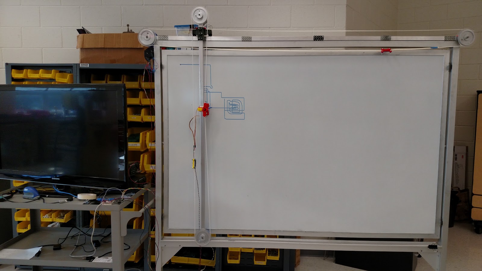

Figure C.3: Rail atop the whiteboard with the wheeled y-axis riding on it.

Figure C.4: CAD drawing of the part seen in green in figure C.3 which held the wheels and vertical axle.

Figure C.5: Electronics, stepper motor, and pulleys which move everything left and right.

Figure C.6: The top of the vertical axis: a stepper motor, pulley, H-Bridge, and a battery.

Figure C.7: Stepper motor configuration at the top of the vertical axis.

Figure C.8: Custom printed bottom wheel attachment piece.
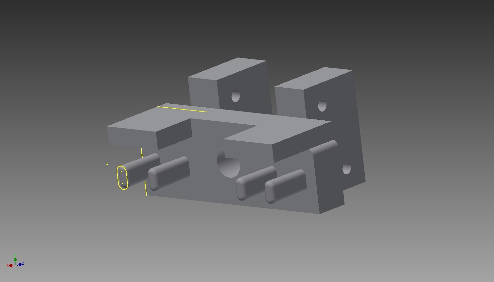
Figure C.9: CAD drawing of bottom wheel attachment piece.

Figure C.10: CAD drawing of the pen holder with smart supports for 3D printing.

Figure C.11: Resulting 3D print with smart supports.
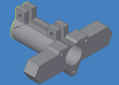
Figure C.12: CAD drawing of the fixed pen holder apparatus.
Appendix D: Electronics
Figure D.1: Electronics Diagram
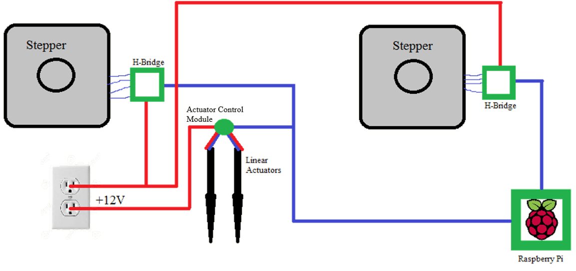
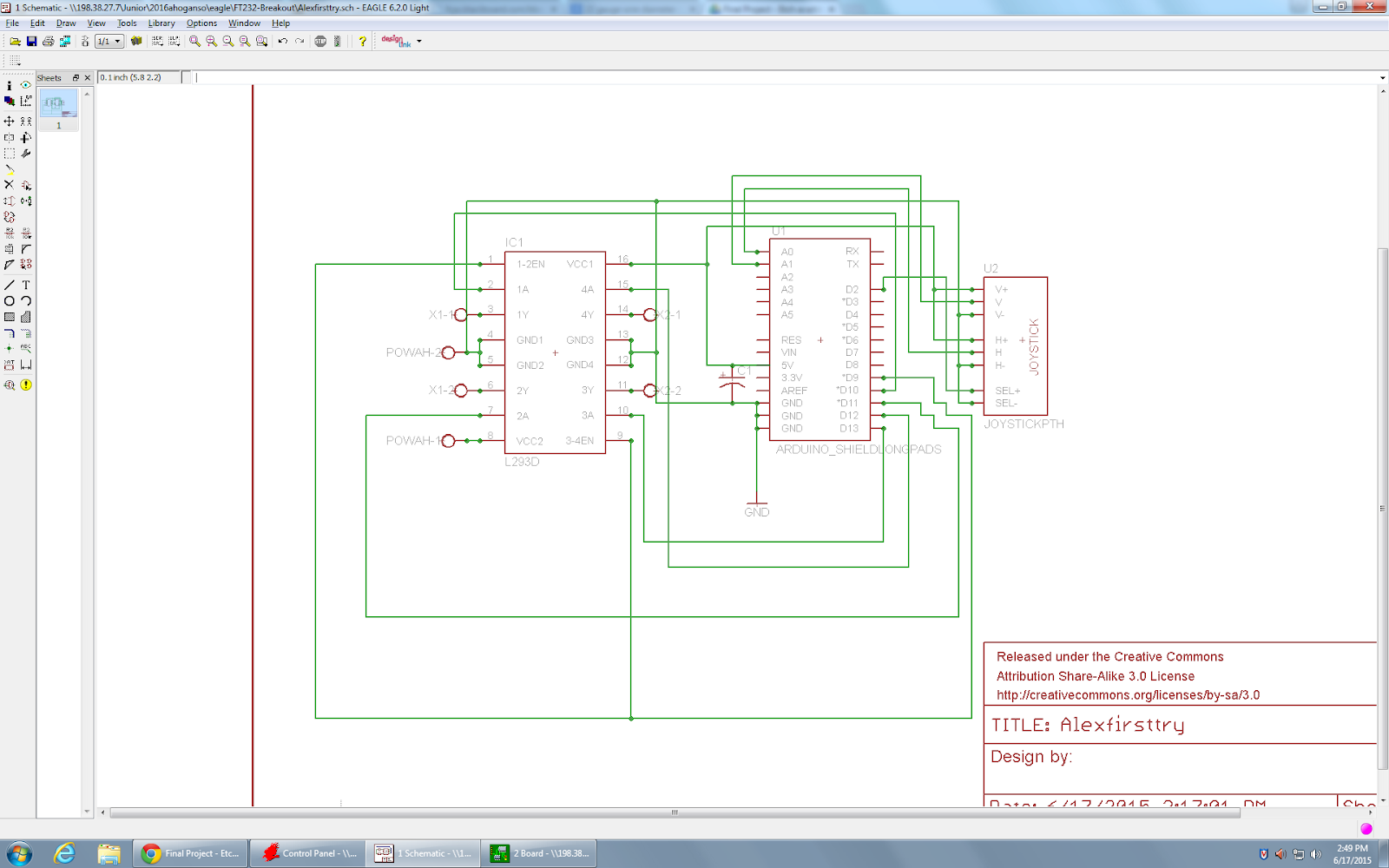
Figure D.2: H-Bridge control electronics used for testing, not in the final project.
Appendix G: Image Processing Code
# findEdges.py
#
# inspired by sample code online, make useful for this project by Nate Foss
#
# Robotics Senior Tech Project 2015-16: Etch-A-Whiteboard
#
import cv2
import numpy as np
import sys
#from matplotlib import pyplot as plt
# NOTE: MUST TAKE A PPM
# convert with: convert image.jpg -compress none image.ppm
filename = sys.argv[1]
img = cv2.imread(filename,0)
edges = cv2.Canny(img,100,200)
#plt.subplot(121),plt.imshow(img,cmap = 'gray')
#plt.title('Original Image'), plt.xticks([]), plt.yticks([])
#plt.subplot(122),plt.imshow(edges,cmap = 'gray')
#plt.title('Edge Image'), plt.xticks([]), plt.yticks([])
#plt.show()
cv2.imwrite(filename[:-4] + 'Edges.jpg', edges)
# NOTE: convert that to ppm after
# +---------------------------------------------------------------------------+
# | Etch-A-Whiteboard instruction file generator |
# | Nate Foss |
# | 5/24/16 |
# | TJHSST Robotics Lab |
# +---------------------------------------------------------------------------+
import sys
from copy import deepcopy
##################################START OF PROGRAM#############################
#======================< GLOBAL STUFFS >===========Instruction File Generator==
#BOARD_WIDTH =
#BOARD_HEIGHT =
WIDTH = 0
HEIGHT = 0
pixScale = 50
DIRECTIONS = [(-1,0),(-1,1),(0,1),(1,1),(1,0),(1,-1),(0,-1),(-1,-1)]
#--------------------------------------------------Instruction File Generator--
def input(filename):
global WIDTH, HEIGHT
txt = open ( filename ) . read() . split()
txt.pop(0)
WIDTH = int(txt.pop(0))
HEIGHT = int(txt.pop(0))
maxRGB = txt.pop(0)
img = [[1 if int(txt[(row*WIDTH + col)*3]) >= 250 else 0 for col in range( WIDTH )] for row in range(HEIGHT)]
return img
#--------------------------------------------------Instruction File Generator--
def outputImage(filename, img):
outfile = open ( filename , 'w' )
outfile.write('P3\n' + str(WIDTH) + ' ' + str( HEIGHT ) + '\n255\n')
for row in range (HEIGHT):
for col in range (WIDTH):
val = '255' if img[row][col] else '0'
outfile.write(val + ' ' + val + ' ' + val + ' ')
outfile.close()
#--------------------------------------------------Instruction File Generator--
def adjacentPixels(img, row, col, exclude = []):
lst = []
for (dr, dc) in DIRECTIONS:
nr , nc = row + dr , col + dc
if nr < 0 or nc < 0 or nr == HEIGHT or nc == WIDTH or (nr,nc) in exclude:
continue
if img[nr][nc]:
lst.append((dr,dc))
return lst
#--------------------------------------------------Instruction File Generator--
def followLineAndPrint(img, drawn, row, col, outfile): #erases from original as it goes, and adds to 'drawn'
#perhaps keep track of last 8 and ignore those (so you can leave some in where there are forks)
# note: can check if corner with boolean = adder[0] and adder[1]
adj = adjacentPixels(img, row, col)
while adj:
dr , dc = 0, 0
if len(adj) > 1:
# have to choose where to go
for d in adj:
if not (d[0] and d[1]):
(dr, dc) = d
break
if not (dr or dc):
(dr, dc) = adj[0]
outfile.write(str(DIRECTIONS.index((dr,dc))) + ' ' + str(pixScale) + '\n')
img[row][col] = 0
drawn[row][col] = 1
row += dr
col += dc
#prep for next time
adj = adjacentPixels(img, row, col)
img[row][col] = 0
drawn[row][col] = 1
return row, col
#--------------------------------------------------Instruction File Generator--
def moveWithPenUp(r1, c1, r2, c2, outfile):
#put pen up
outfile.write('8 1\n')
#move
dirx = 2 if c2 > c1 else 6
diry = 0 if r2 < r1 else 4
outfile.write(str(dirx) + ' ' + str(pixScale * max(c1-c2,c2-c1)) + '\n')
outfile.write(str(diry) + ' ' + str(pixScale * max(r1-r2,r2-r1)) + '\n')
#put pen down
outfile.write('9 1\n')
#===============================< MAIN >========================================
def main():
filename = sys.argv[1]
img = input(filename)
#pixScale = min(BOARD_WIDTH/ WIDTH, BOARD_HEIGHT / HEIGHT)
outfile = open(filename[:-4] + '.eaw', 'w')
drawn = [[0 for col in range(WIDTH)] for row in range(HEIGHT)]
#assume pen starts at 0,0
pr = 0
pc = 0
count = 0
for row in range(HEIGHT):
for col in range(WIDTH):
if img[row][col]:
print('it happened')
moveWithPenUp(pr,pc,row,col, outfile)
pr, pc = followLineAndPrint(img, drawn, row, col, outfile)
#outputImage(filename[:-4] + str(count) + '.ppm', drawn) #for debugging
count += 1
outfile.close()
#--------------------------------------------------Instruction File Generator--
if __name__ == '__main__': from time import clock; START_TIME = clock(); main(); \
print('--> Run time =', round(clock() - START_TIME, 2), 'seconds <--');
#############################< END OF PROGRAM >#################################
Appendix H: Image Processing Results

Figure H.1: TJ Star logo, used here as an example image to process

Figure H.2: image after grayscale

Figure H.3: edges of image after detection and thinning
Appendix I: Movement and Instruction File Reading Code
# +---------------------------------------------------------------------------+
# | Etch-A-Whiteboard movement methods |
# | Nate Foss |
# | 5/24/16 |
# | TJHSST Robotics Lab |
# +---------------------------------------------------------------------------+
import RPi.GPIO as GPIO
import time
import sys
#import multiprocessing
#======================< GLOBAL STUFFS >==============================Movement==
delay = 0.002
#A1 A2 B1 B2 #B2 is closest to power on the H-Bridge module
stepperPins = [[26, 19, 13, 6],
[12, 16, 20, 21]]
# stepperPins row 0 is horizontal, 1 is vertical
actuatorPinPurple = 23
actuatorPinWhite = 24
#---------------------------------------------------------------------Movement--
def initSteppers():
GPIO.setmode(GPIO.BCM)
GPIO.setwarnings(False)
for lst in stepperPins:
for pin in lst:
GPIO.setup(pin, GPIO.OUT)
GPIO.setup(actuatorPinPurple, GPIO.OUT)
GPIO.setup(actuatorPinWhite, GPIO.OUT)
GPIO.output(actuatorPinWhite, 0)
GPIO.output(actuatorPinPurple, 0)
print('--Initialization complete.')
#---------------------------------------------------------------------Movement--
# should be in format [dir, steps,]
def parseLine(lineList):
print(lineList)
lineList = [int(lineList[x]) for x in range(len(lineList))]
if lineList[0] < 8:
print('move?')
input()
move(lineList[0], lineList[1])
else:
[penup, pendown][lineList[0]-8]()
#---------------------------------------------------------------------Movement--
# Function for step sequence
def setStep(s, w1, w2, w3, w4):
GPIO.output(stepperPins[s][0], w1)
GPIO.output(stepperPins[s][1], w2)
GPIO.output(stepperPins[s][2], w3)
GPIO.output(stepperPins[s][3], w4)
#---------------------------------------------------------------------Movement--
def up(steps):
for x in range(steps):
stepCounterclockwise(1)
#---------------------------------------------------------------------Movement--
def upright(steps):
for x in range(steps):
stepCounterclockwise(1)
stepClockwise(0)
#---------------------------------------------------------------------Movement--
def right(steps):
for x in range(steps):
stepClockwise(0)
#---------------------------------------------------------------------Movement--
def downright(steps):
for x in range(steps):
stepClockwise(0)
stepClockwise(1)
#---------------------------------------------------------------------Movement--
def down(steps):
for x in range(steps):
stepClockwise(1)
#---------------------------------------------------------------------Movement--
def downleft(steps):
for x in range(steps):
stepClockwise(1)
stepCounterclockwise(0)
#---------------------------------------------------------------------Movement--
def left(steps):
for x in range(steps):
stepCounterclockwise(0)
#---------------------------------------------------------------------Movement--
def upleft(steps):
for x in range(steps):
stepCounterclockwise(0)
stepCounterclockwise(1)
#---------------------------------------------------------------------Movement--
def penup():
GPIO.output(actuatorPinPurple, 1)
time.sleep(5)
GPIO.output(actuatorPinPurple, 0)
#---------------------------------------------------------------------Movement--
def pendown():
GPIO.output(actuatorPinWhite, 1)
time.sleep(5)
GPIO.output(actuatorPinWhite, 0)
#---------------------------------------------------------------------Movement--
def stepClockwise(stepper):
setStep(stepper, 1,0,0,1)
time.sleep(delay)
setStep(stepper, 0,1,0,1)
time.sleep(delay)
setStep(stepper, 0,1,1,0)
time.sleep(delay)
setStep(stepper, 1,0,1,0)
time.sleep(delay)
#---------------------------------------------------------------------Movement--
def stepCounterclockwise(stepper):
setStep(stepper, 1,0,1,0)
time.sleep(delay)
setStep(stepper, 0,1,1,0)
time.sleep(delay)
setStep(stepper, 0,1,0,1)
time.sleep(delay)
setStep(stepper, 1,0,0,1)
time.sleep(delay)
#---------------------------------------------------------------------Movement--
def move(direction, steps):
fnct = [up, upright, right, downright, down, downleft, left, upleft][direction]
fnct(steps)
#===============================< MAIN >========================================
def main():
# DO STUFF HERE
print('flag1')
if len(sys.argv) > 1:
# NOTE: input should be in the form int , int where the first int is
# direction, and the second is the number of steps.
# This is the same format as the instruction file.
initSteppers()
parseLine(sys.argv[1:])
#------------------------------------------------------------Etch-A-Whiteboard--
if __name__ == '__main__': main()
#############################< END OF PROGRAM >#################################
# +---------------------------------------------------------------------------+
# | Etch-A-Whiteboard driver |
# | Nate Foss |
# | 5/24/16 |
# | TJHSST Robotics Lab |
# +---------------------------------------------------------------------------+
import sys
#import RPi.GPIO as GPIO
import time
import Movement
###################################START OF PROGRAM#############################
#===============================< MAIN >========================================
def main():
Movement.initSteppers()
filename = sys.argv[1]
print('Reading from file', filename)
f = open ( filename )
line = f.readLine()
while(line):
print(line)
Movement.parseLine(line.strip().split())
line = f.readLine()
#------------------------------------------------------------Etch-A-Whiteboard--
if __name__ == '__main__': main()
#############################< END OF PROGRAM >#################################