 Arthur Admiraal
As of writing this log, the build is finally completed, which allows me to talk about the design decisions concerning the mechanical side of this project, since I now have the photographs to illustrate them. In this post I will only talk about what connects to what, details will be provided in the building instructions.

Construction
The base
Let's start with the base. Al this needs to do is provide some stability and hold up the rest of the setup high enough to slide through a reservoir of a testing solution, not the floor. Hence, the base just consists of a long, rectangular piece of plywood, in which two thick pieces of wood are screwed.
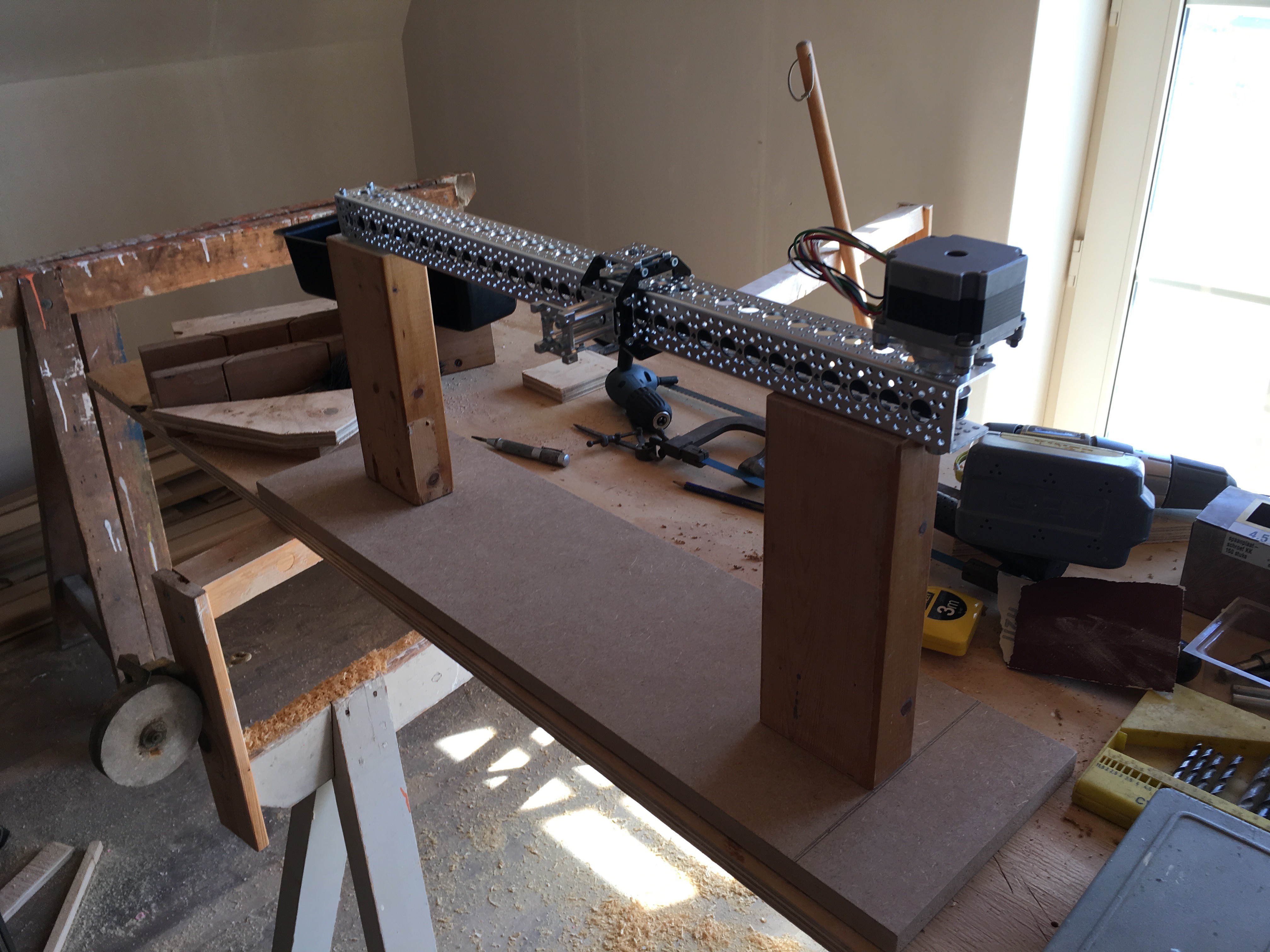
The slider
The slider is attached to these pieces of wood using some wood screws. It is just a regular actobotics slider kit, although I have made a couple of minor modifications.
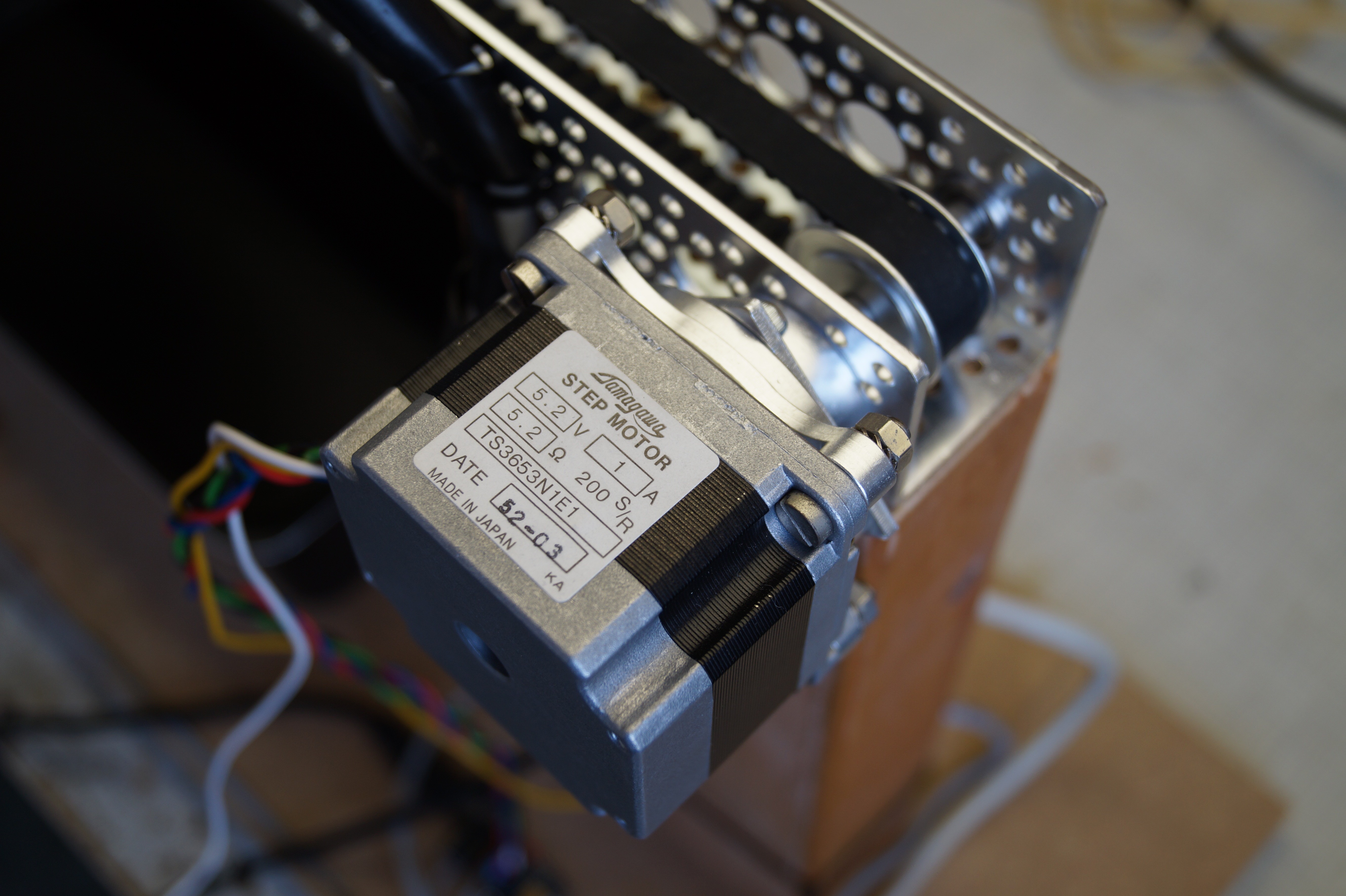
I have used a stepper motor to drive it instead of the usual DC motor. Using a stepper motor allows for precision repeatable positional control, and thus also precision speed control. Because of this, they are generally used in precision applications, such as 3D printers and CNC machines. Since I want the experiment to be repeatable, I thought it was appropriate to use one here.
Obviously, I have left the feed off, since they would get in the way of mounting it to the base.
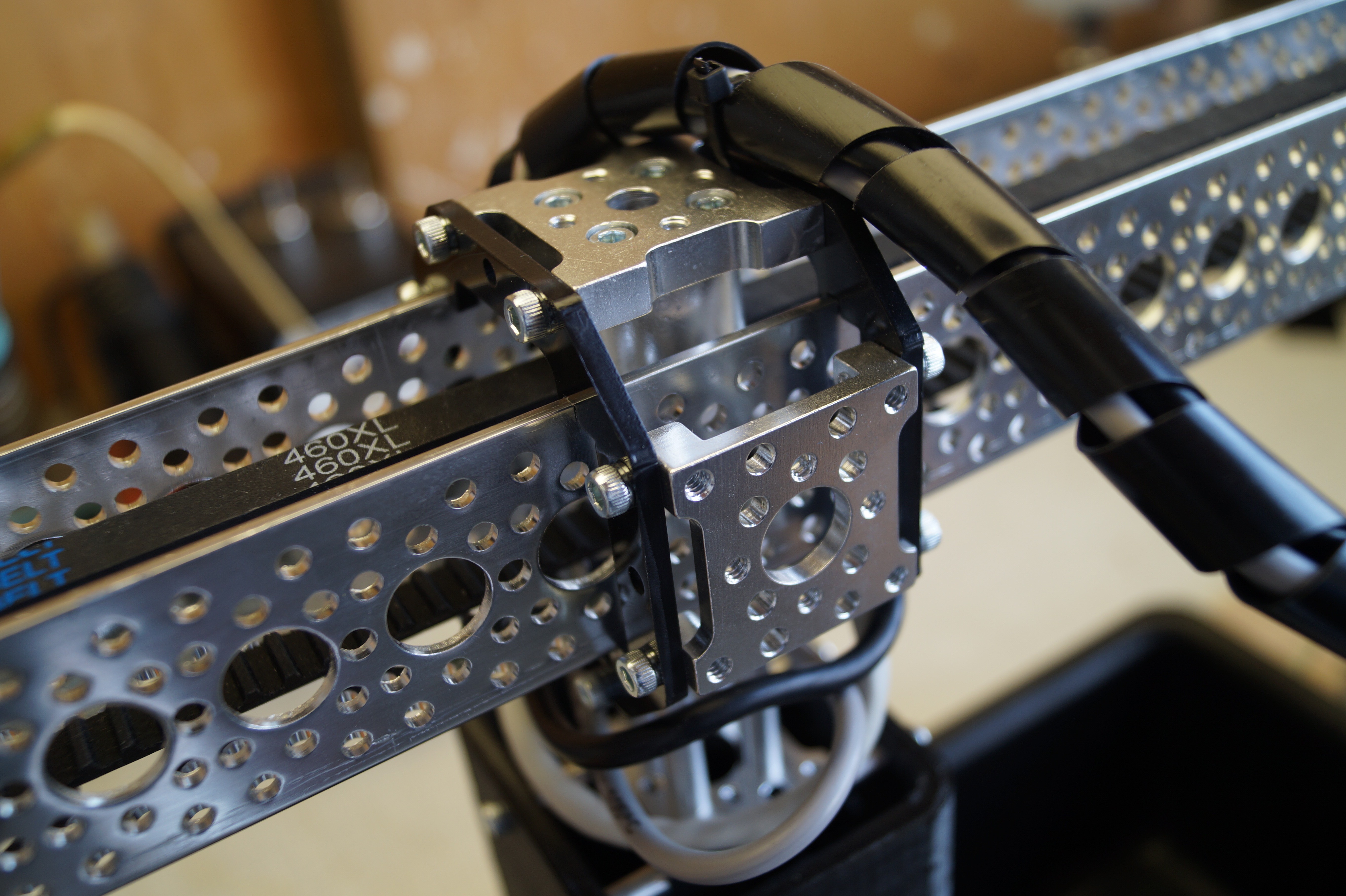
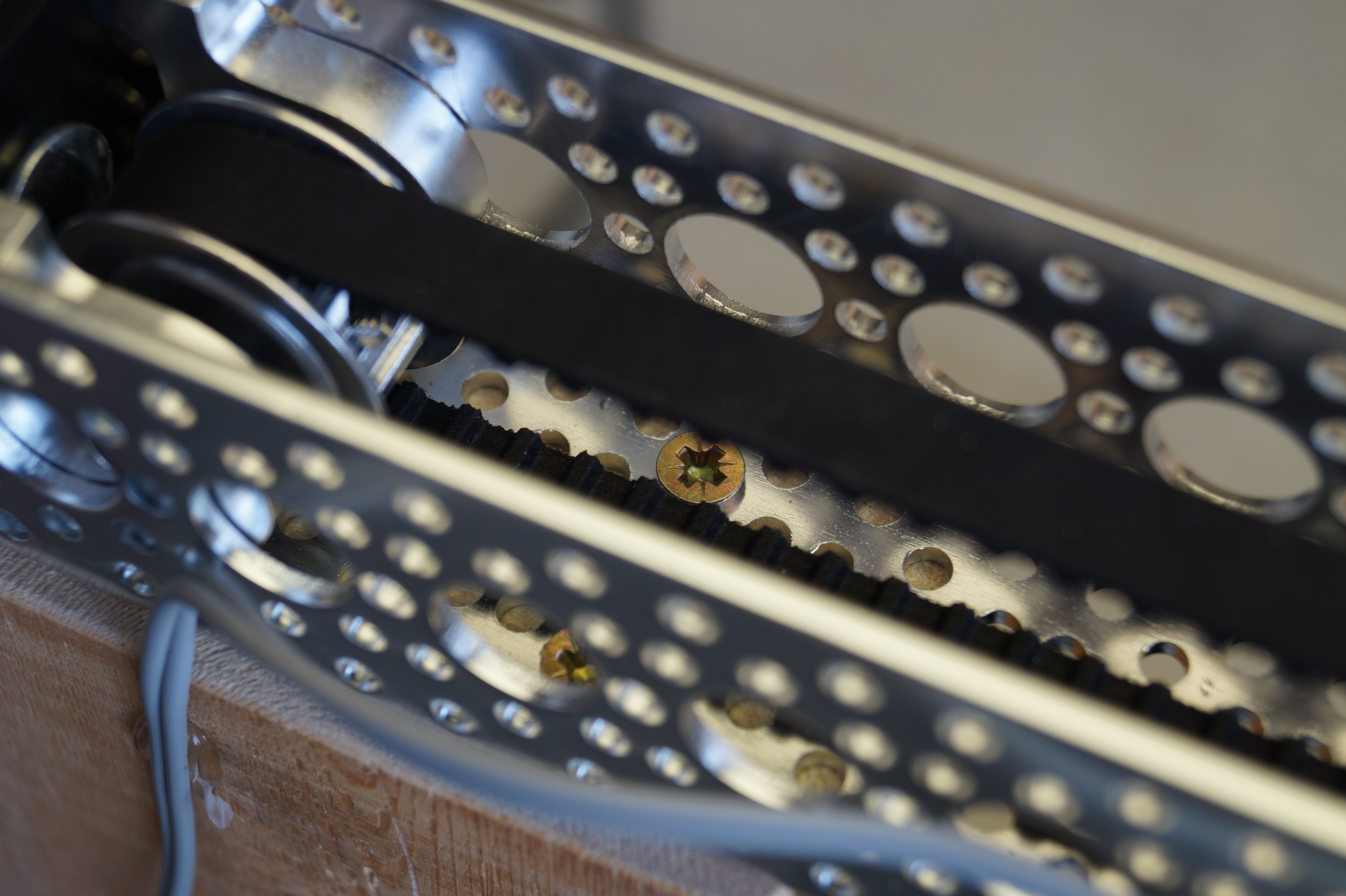
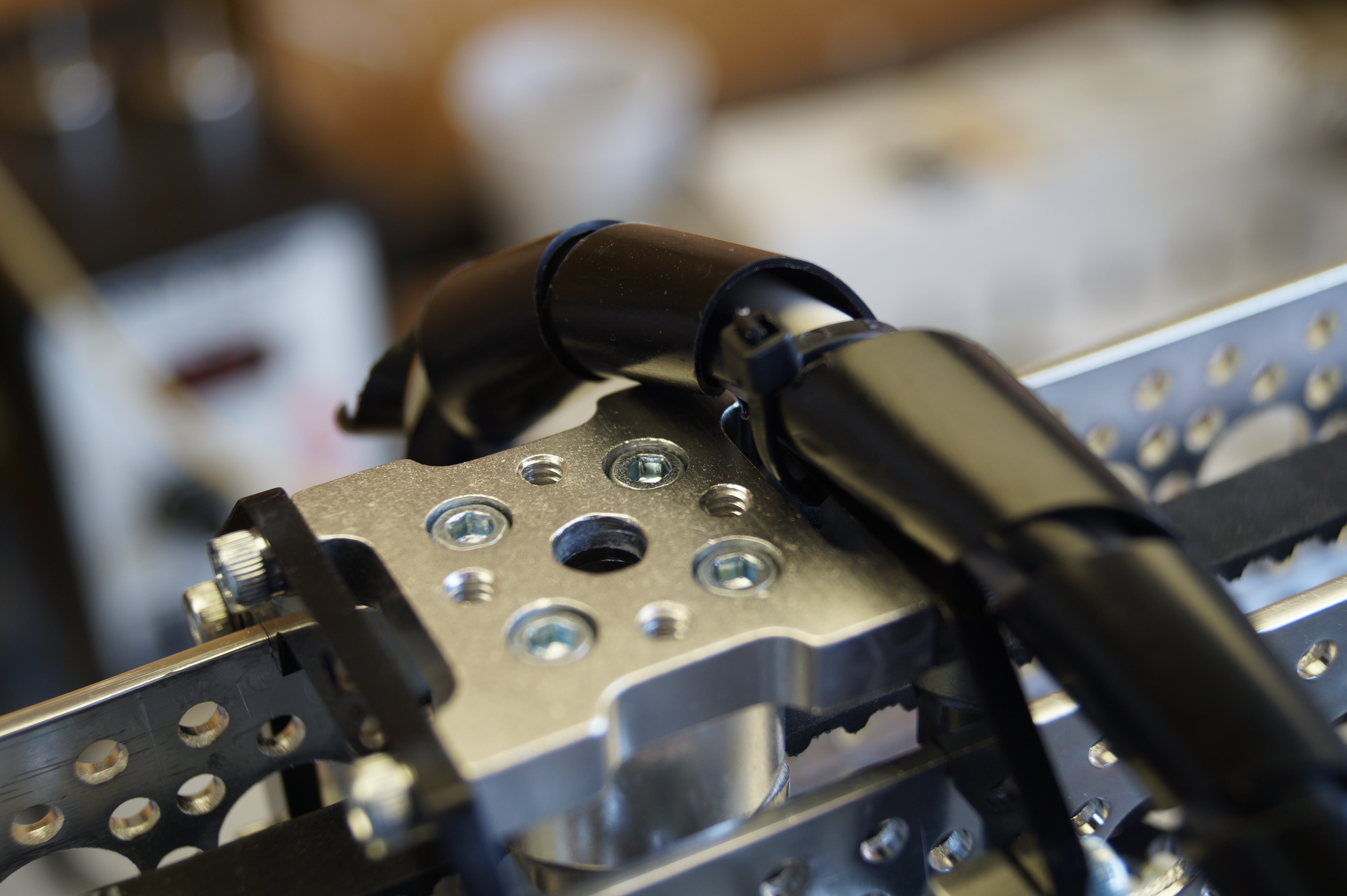
Lastly, instead of the sliders D that came with the kit, I used some channel sliders A and 2 additional hub mounts to create a more solid structure to slide around the aluminium channel, which also has mounting points on the underside. Using some 1.32" standoffs, another hub mount is mounted to this bottom. By sawing the head off some screws, I was able to create male to female standoffs, which I used to mount RISA to this slider assembly.
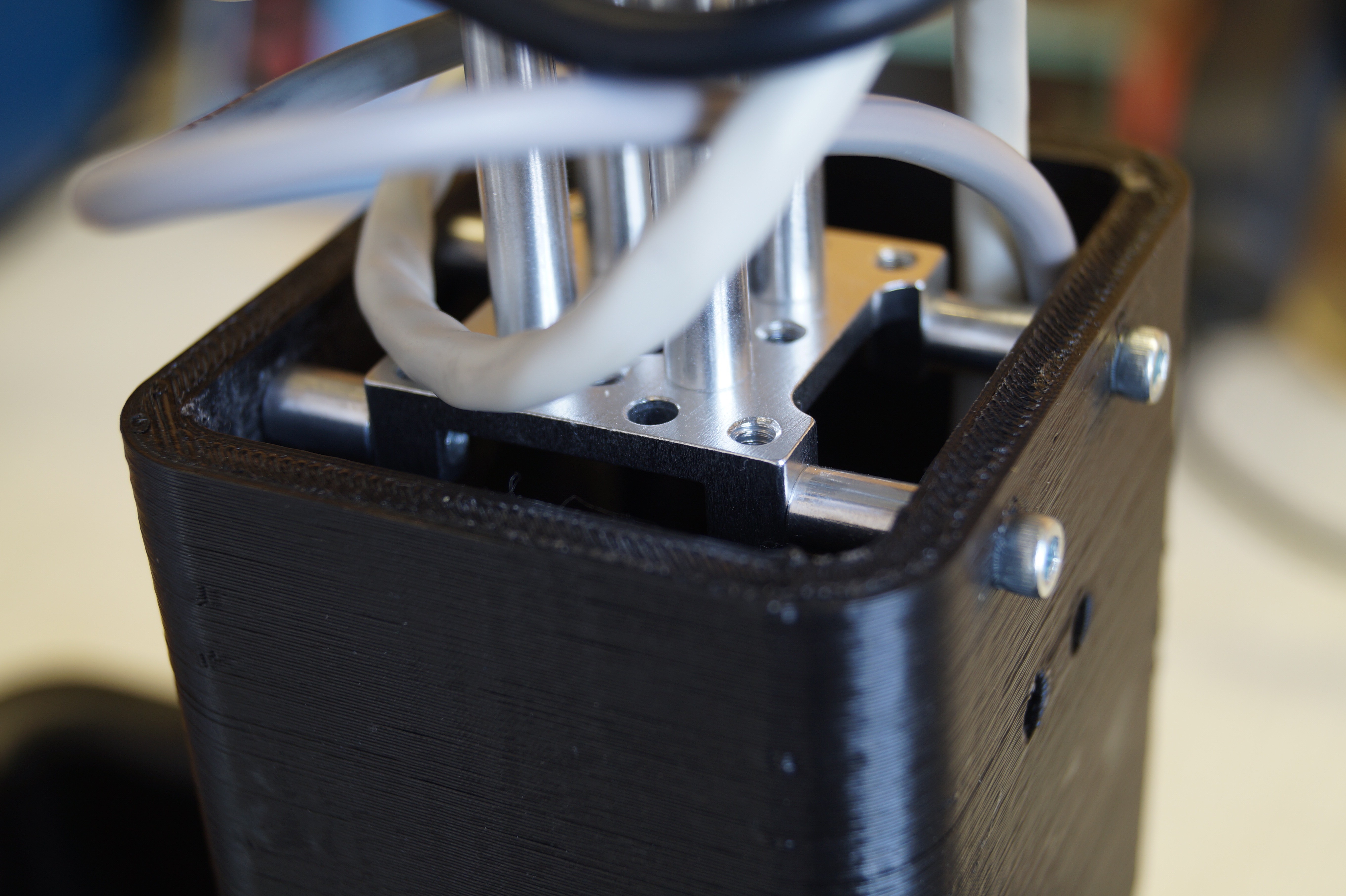
RISA
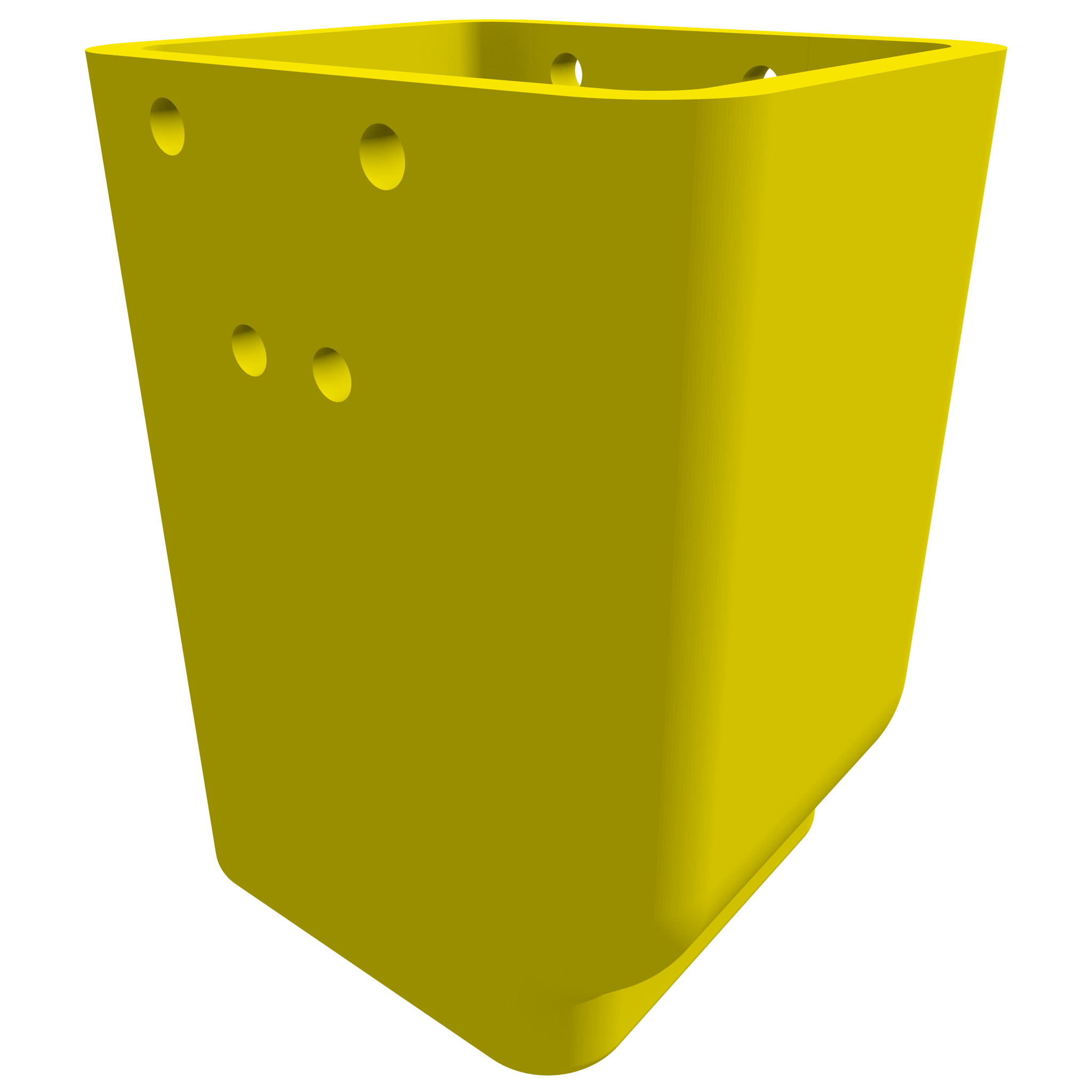
The construction of RISA is the the most intricate, but still very straightforward. I wanted to be able to disassemble it, so I could make modifications if necessary. It also has to be at least somewhat waterproof, as the the electrode array will be submerged. Let's go through the design from top to bottom.
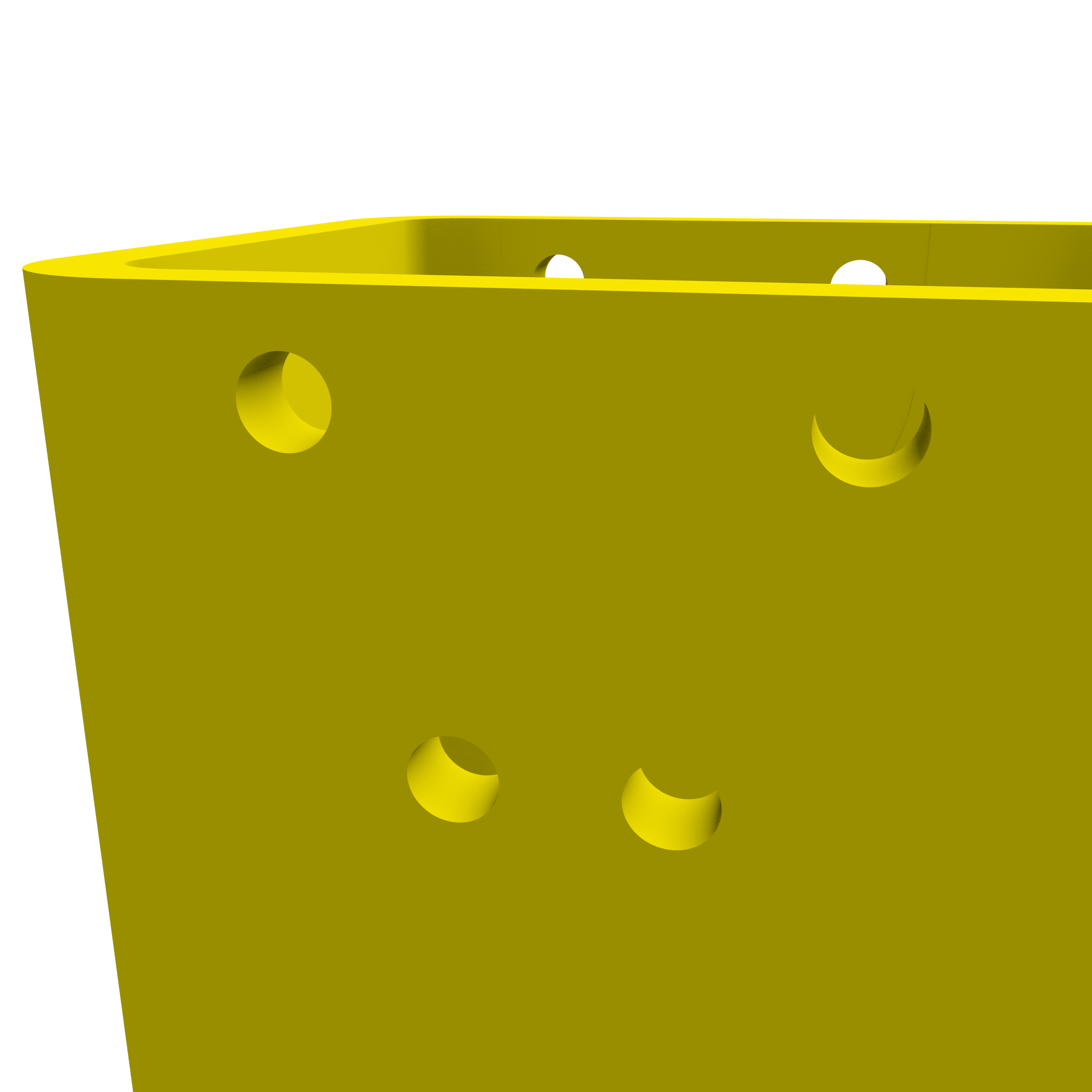
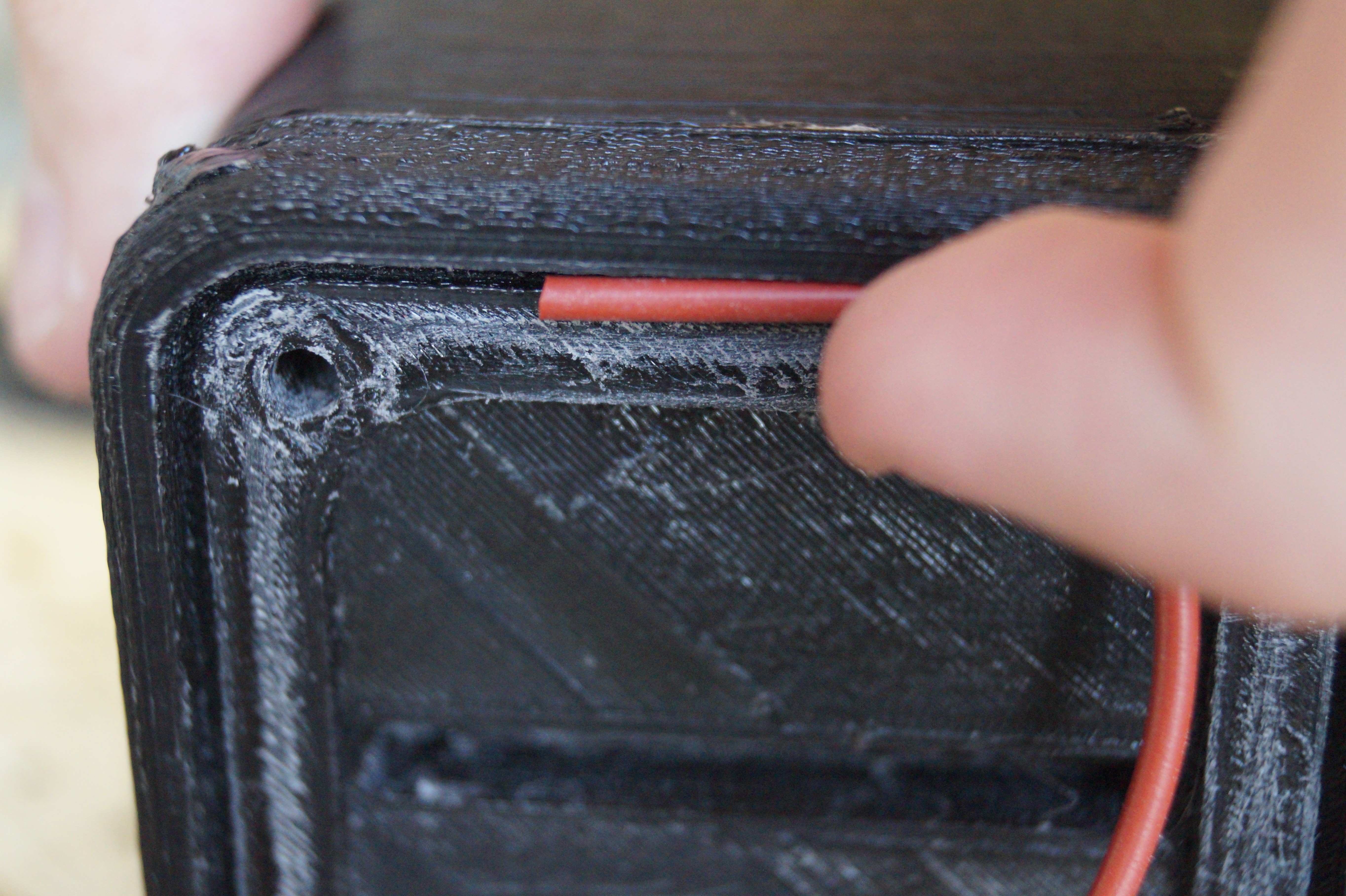
At the top of RISA, we find some mounting holes, 4 on each side. There are this many so that it could also be used under a 45 degree angle.Next, there is a shaft, through which the signal generator PCB can be slid into position.
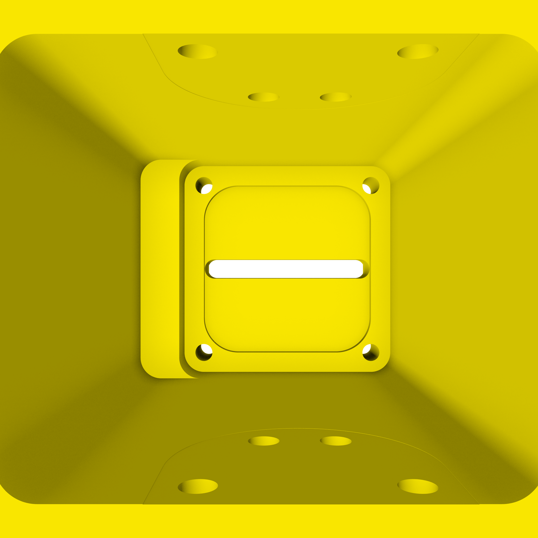
There is a slight widening of the shaft, to provide enough space for the
USB connector connected to the teensy. I couldn't find anything
smaller, so I had to make this compromise.
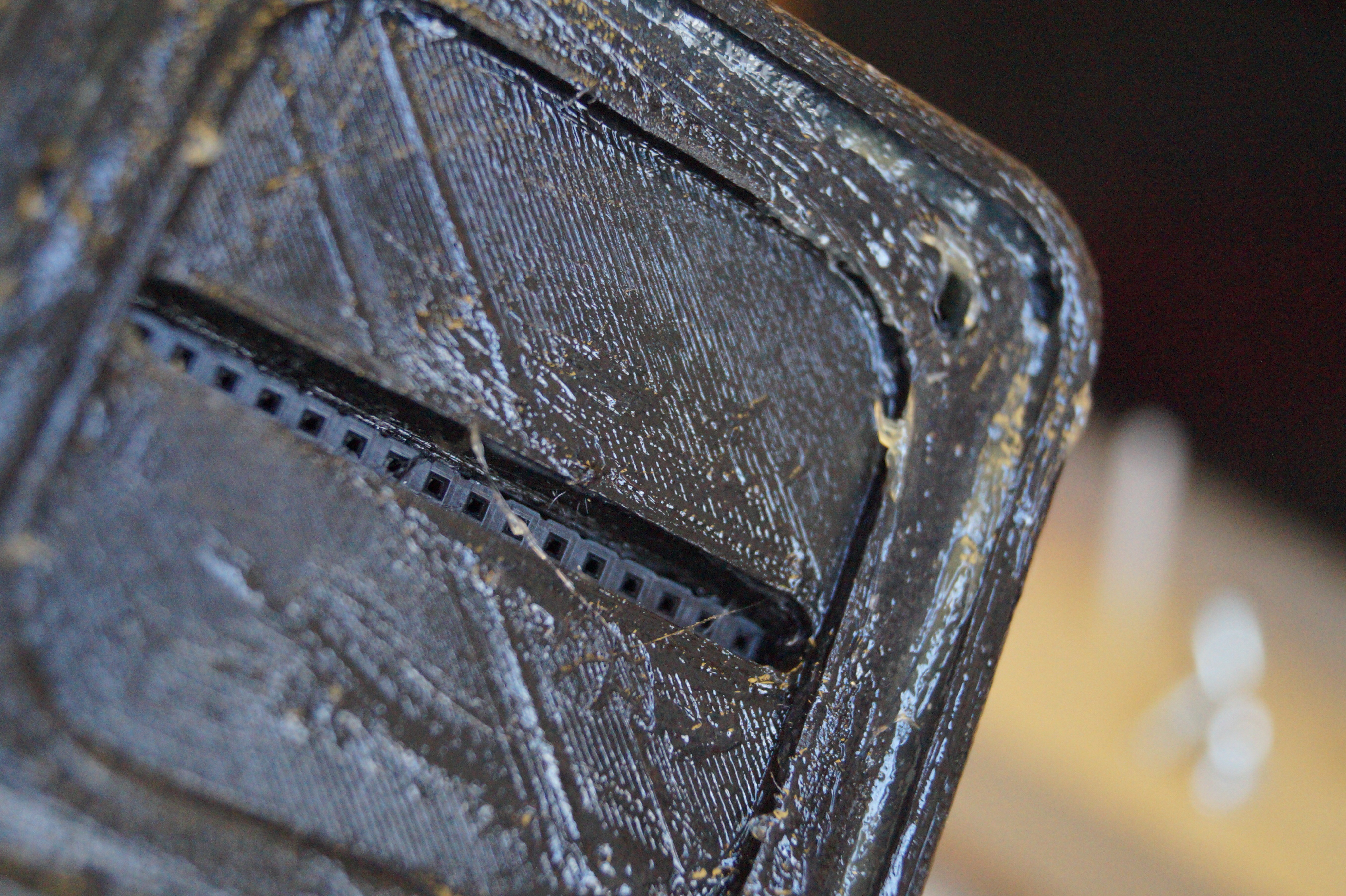
The electrode PCB has a pocket on the bottom of the part in which it sits. The two boards are connected by a .1" header, which connects through a slid in the part.
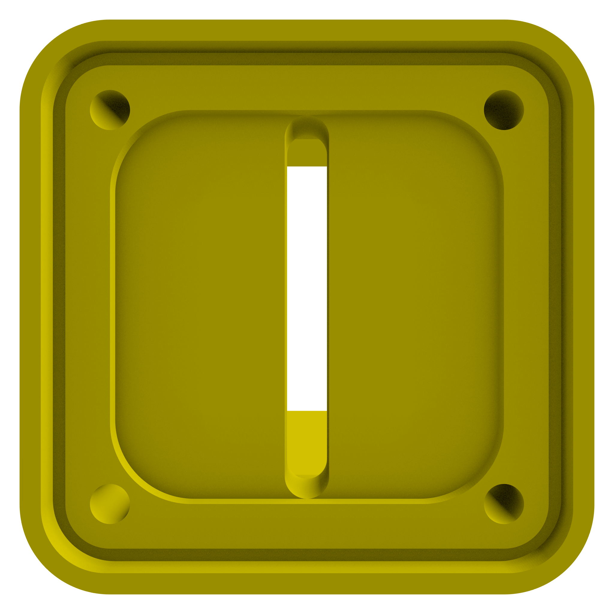
Notice how both PCBs have an additional pocket under there mounts. For the electrode PCB, this provides clearance for the SMT parts on it's backside, while the pocket solely provides clearance for the solder joints on the bottom of the signal generator PCB.
I planned for the boards to be held in place by 4 bylon countersunk screws, which would be glued in place so the assembly would be waterproof. Some nuts would then screw on them on the signal generator board to sandwich the whole construction in place. It was important to use countersunk screws so that they wouldn't disturb the laminar flow during measurements. They had to be some type of plastic to prevent the metal releasing unwanted ions into the solution or influencing the conductivity of it.
I had to countersink the holes in the electrode PCB myself, since the low-cost PCB manufacture services I know of don't provide countersunk holes.
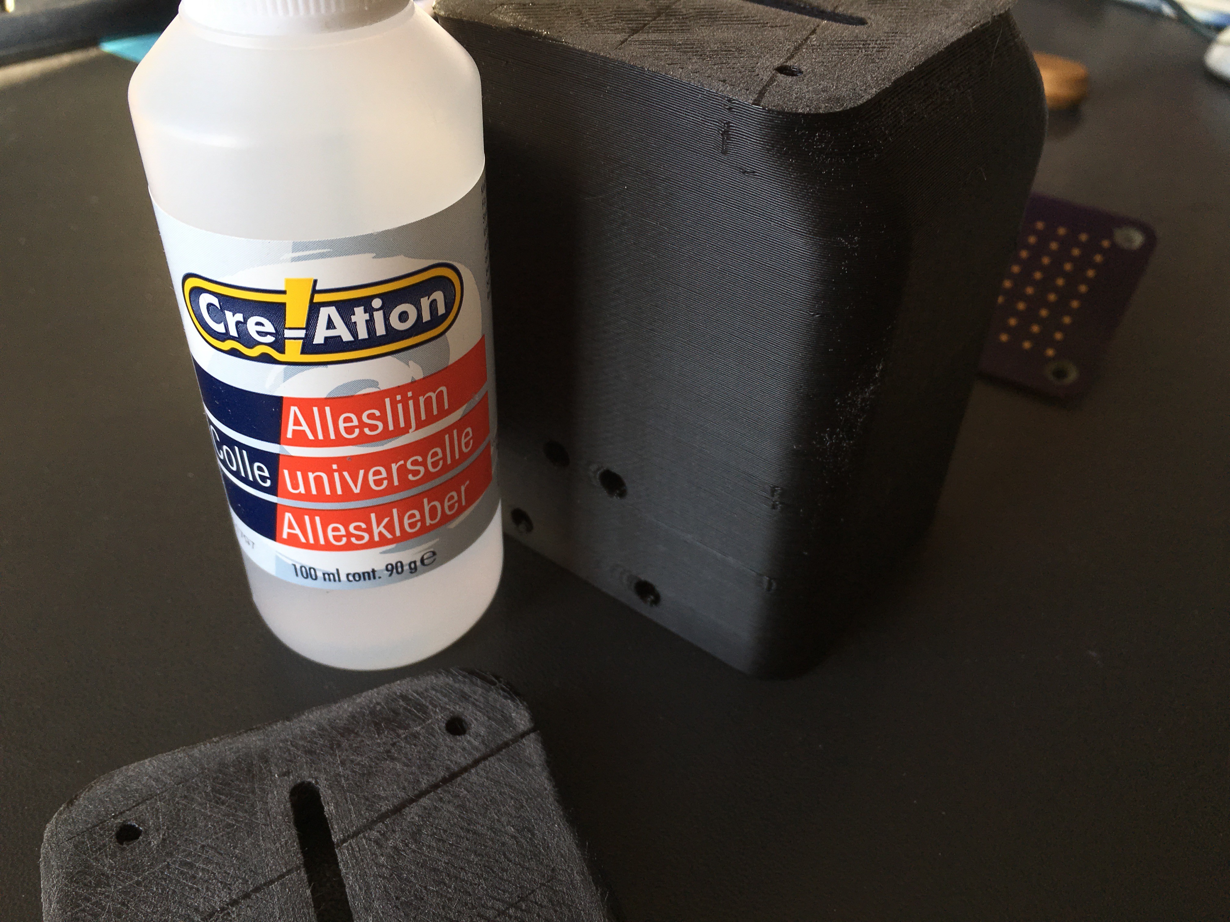
However, I didn't leave enough space for a nut close to the headers of the Teensy, so that it would become difficult to use them. I decided to just screw them in and use some grease for waterproofing, since the seal doesn't have to handle any pressure. On my prototype 3D-print of the part, they tapped themselves into the part, so that I didn't even need nuts. On my second run of parts, this didn't work however. They do provide some clamping force, but not very much.
I was planning to use an O-ring to seal the electrode PCB, but it didn't fit in the 3D-printed part. This meant that I didn't need all that much clamping force so that the headers on the PCBs seem to provide enough force to hold everything together.
I could reprint the part or file a nut down, but I want to get something working fast, so I decided to just put a lot of grease on the seal and call it a day.
Another interesting aspect of the design is the rounded corners. These have been made so that the flow is as laminar as possible. Furthermore, I 3D-printed this part, but you may have noticed that it has cutouts on both sides of the parts, so that it becomes almost impossible to print on entry-level 3D printers. Because of this, I printed the top and bottom of the part separately, and glued them together later. Unfortunately, I haven't quite perfected my 3D-printing, so that the parts aren't quite perfect. Especially the warping is quite bad, but shouldn't be an issue for my experiments.
Reservoir
I am using a simple cake tin as a reservoir to hold the solution on which I will experiment. It is made of metal, but it has a coating which I have confirmed to be non-conductive.
Additional electronics
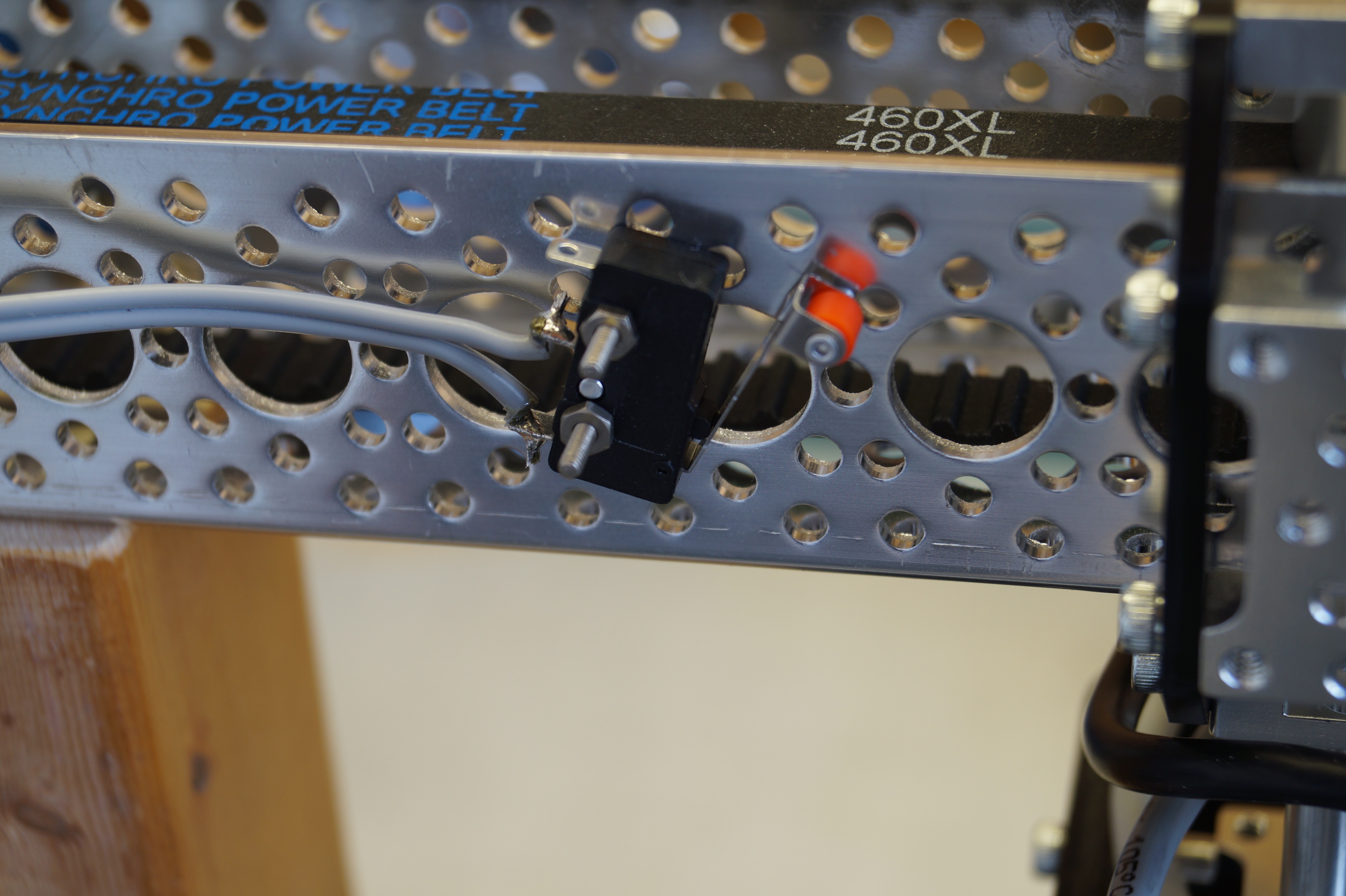
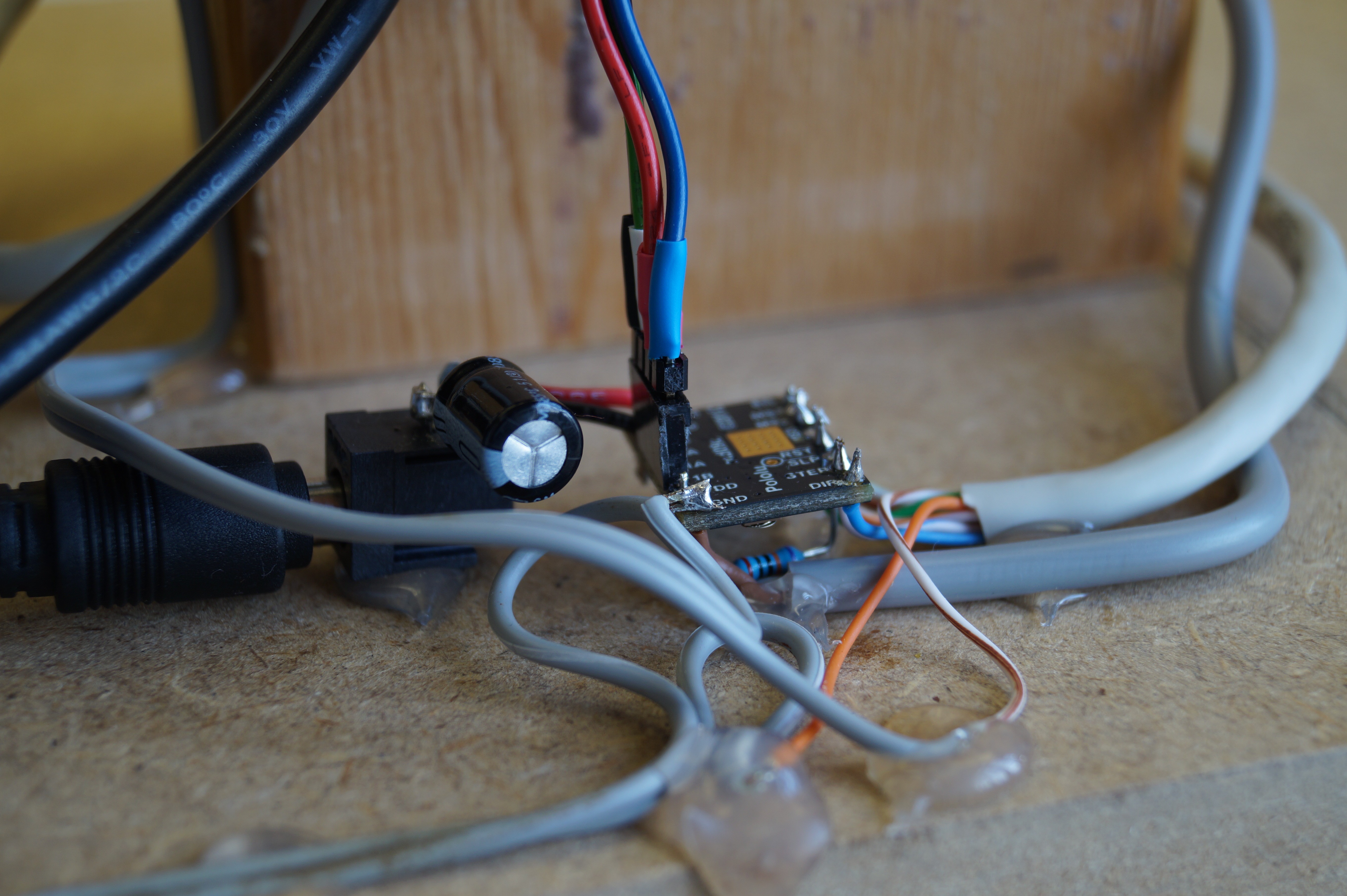
To drive the stepper motor, a small driver board was needed, along with some limit switches to make sure the setup doesn't destroy itself. To connect to these and to the computer, some cables have to be run to RISA. I had already made a header for the stepper motor connections, but I forgot to include limit switch connections and the logic supply for the stepper motor driver. To fix this, I soldered a bodge wire to another point on the signal generator board and repurposed the I/O meant to go to the enable and sleep pins as inputs for the limit switches, since I really don't need to change the sleep mode of the stepper motor driver.

I used an ethernet cable and some two-conductor cable to route all the connections to the driver board, where some split of to the limit switches. I connected to those by another two-conductor cable.
At this point, I had a lot of cables. That's all fine and dandy, but when the slider starts moving, I don't want any of them to get pulled, so cable management was needed. I stuck down the cables of the limit switches with hot glue.
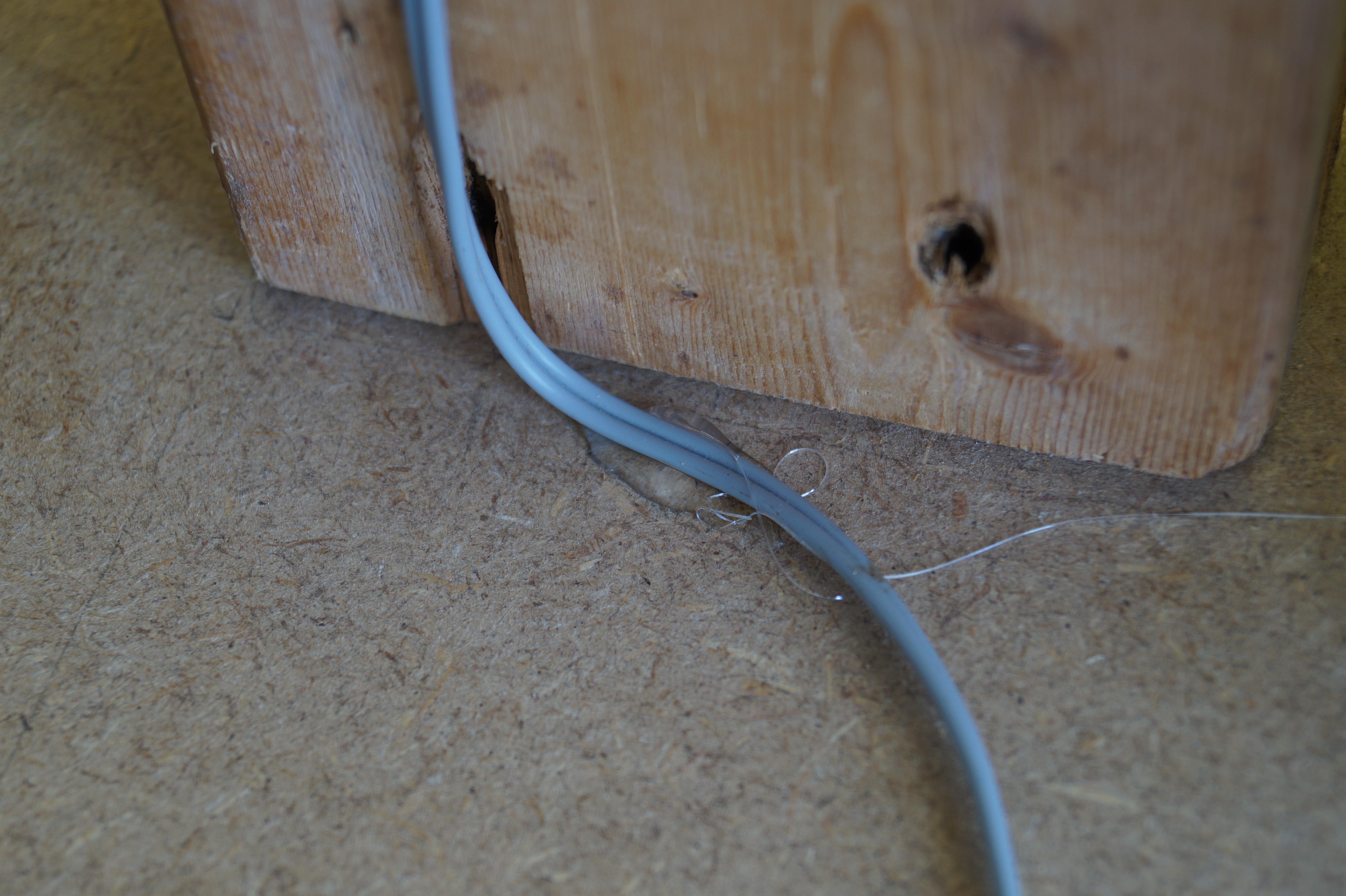
The three cables coming of of RISA were fed through a cable guide, which was stuck down with cable ties.
I also twisted the cables coming of of one coil of the stepper motor together, and than twisted those pairs again so that these cables would be held together. I put a tie rap on them to prevent them from untangling.
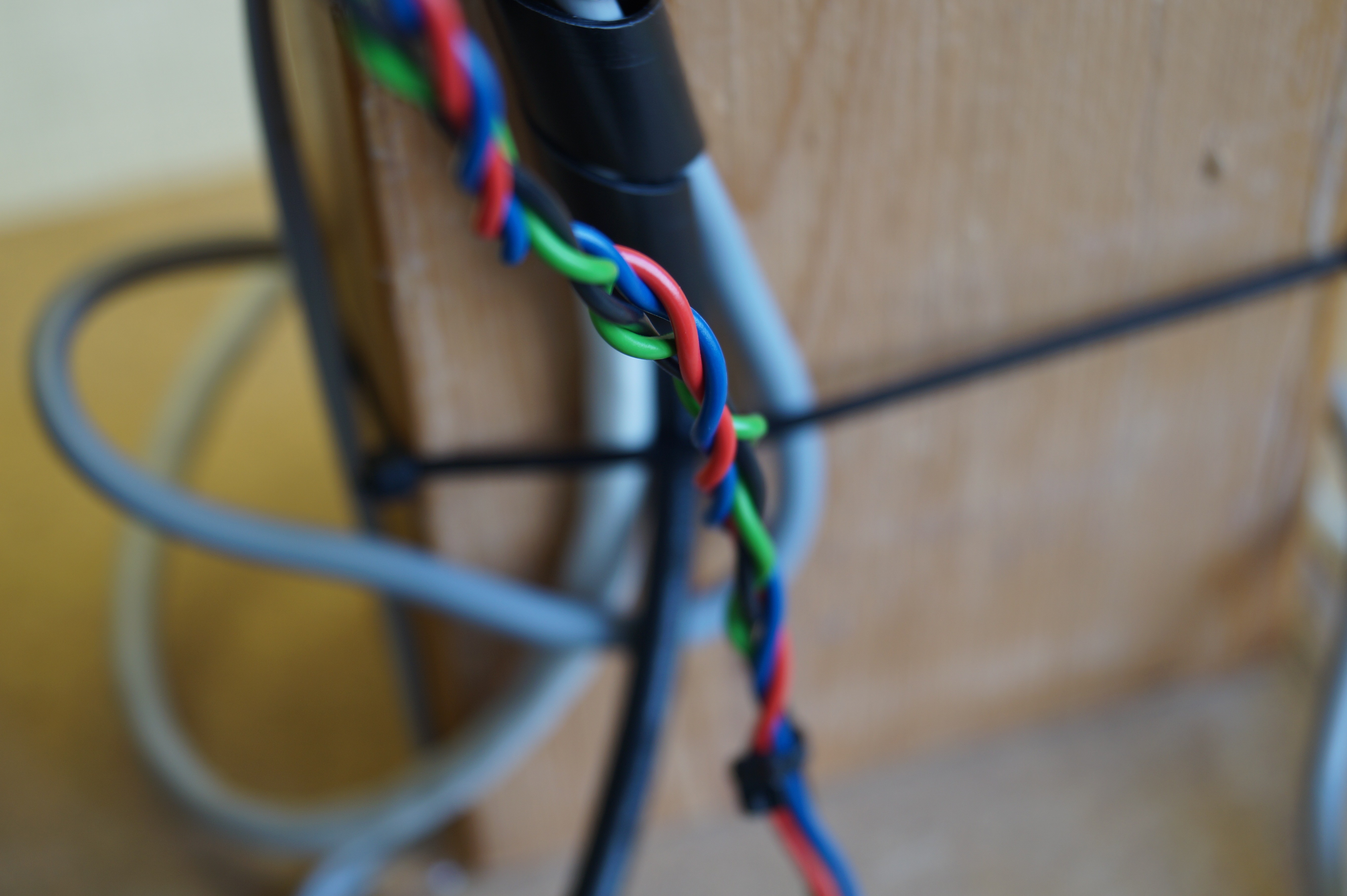
I think these simple things made the cabling quite neat.
Testing
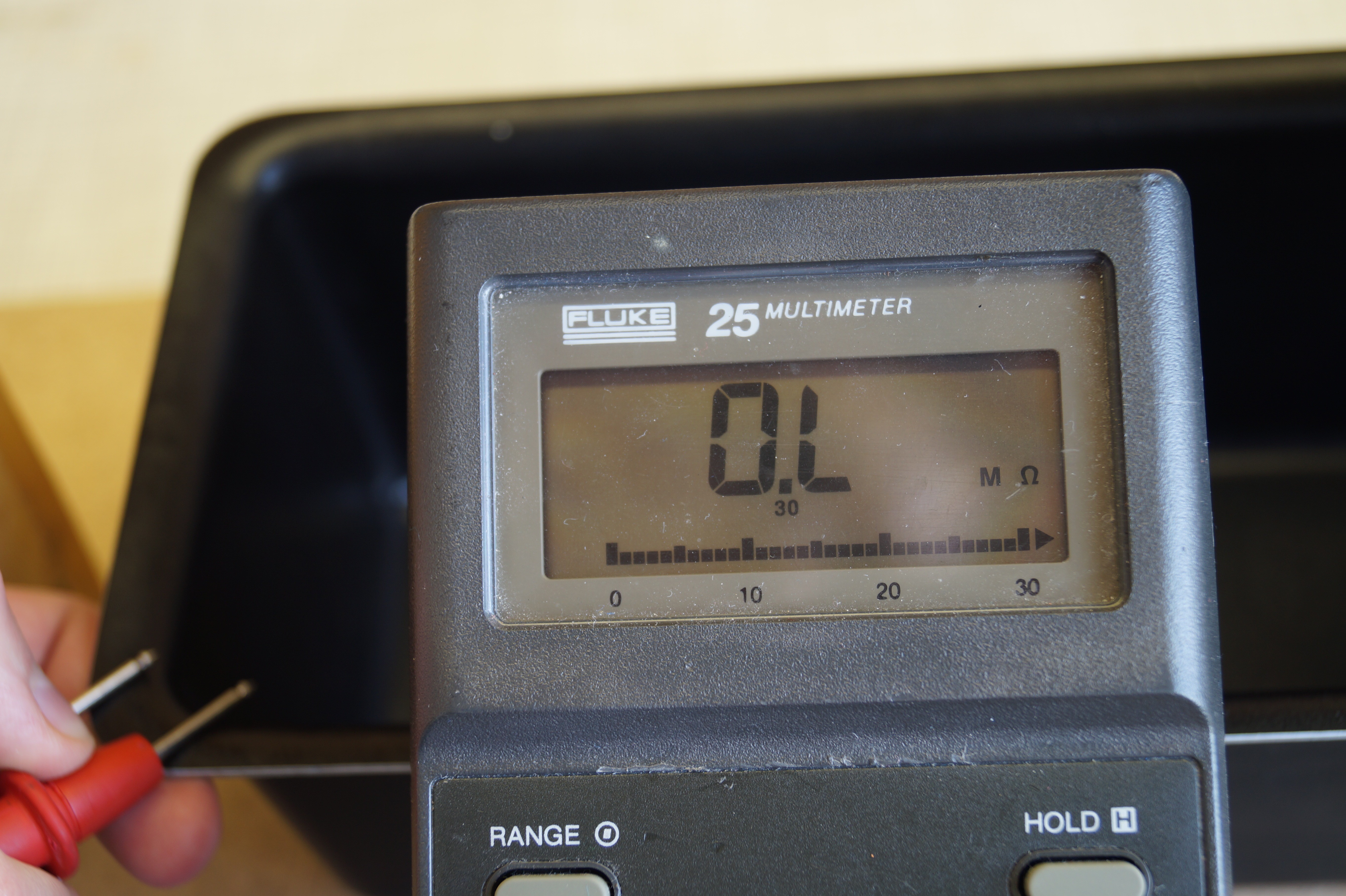
After building the setup, I immediately tested whether the stepper motor turned. It did, but after reprogramming the Teensy it did not. When reprogramming the Teensy, the motor made a terrible buzzing sound, probably because the signals to program the Teensy are on the same lines as the stepper motor control pins.
I measured all signals going to the stepper driver, and even used my oscilloscope to examine the waveforms going to the stepper motor, but everything seemed fine. The stepper motor even heated up as normal and made a nice buzzing sound, which changed with the frequency of the pulses on the STEP of the stepper motor driver.
It was only then that I took a look at the axle of the stepper motor and saw that the grub screw of the shaft coupler had vibrated loose. After tightening it down, everything worked as normal. It hasn't come of since, but I may apply some loctite or something similar if it does.
This was a bit of a facepalm moment for me, but at least I won't make this error in the future.
Anyhow, now the mechanical part of the setup is working great!

It looks like all the hardware is up and running, so next up will be the programming.
Discussions
Become a Hackaday.io Member
Create an account to leave a comment. Already have an account? Log In.