 numero_trey
Sensors on a car are tricky. Most are single-wire variable resistors to ground of very low value. According to the service docs, the fuel level sensor reads from 110-2 ohms (I have not yet clamped a meter on the sensor and read the actual values). This makes designing the voltage dividers tricky. I don’t want to sink too much current through them, and I want to get a good range of values from the AD converter.
The Math
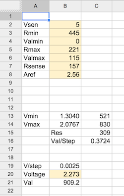
I started by sketching out some different values for the sense resistor on a spreadsheet. The sheet I used allowed me to enter voltage to the sensors (Vsen), sensor min/max resistance, sensor min/max measured range (eg. 0-120 psi), the sense resistor value, and the reference voltage (Aref). It calculates the min/max voltage output, the min/max AD readings, the reading delta, and the real units per AD step (eg. 0.34psi/step). This allowed me to try dozens of sensor configurations and find the best configuration for all of the sensors.
To measure engine voltage, I went with a 10-turn 10k pot as a simple voltage divider with some simple filtering. I worked backwards from a desired 0.02v/step (~20v range over 10 bits) and calibrated the pot with a multimeter and a stable voltage source.
I decided to feed the sensors with 5v and use the 2.56v internal Aref in order to make my voltage dividers simpler and to alleviate my fear of a sensor going open circuit and dumping 12v into my AVR input. I’m worried about noise at such low voltages, but I think I can filter enough to mitigate.
Revolutions
Reading the RPM of the engine is a tricky problem, especially when you don’t have a running engine to develop on. You are trying to measure a high-voltage, very noisy circuit that requires lots of protection and possibly analog filtering. I played around with low-pass filter designs and schmitt triggers in case I need them once I get ahold of a running engine. At the time I was trying to have the system working for our first race in Feb 2014, so I wanted to make sure I ordered everything I might need. This meant I had to sketch out lots of variations and order the parts to build them all (all on spreadsheets). I tried to vary as few components as possible to limit my order.
Reading
I had to design firmware for the AVR to read all of these values. The sensors were fairly straightforward. I found code online to read a value from the AD x times, throw away the highest and lowest y values, and average. At the moment, I am reading 20 values and discarding the top and bottom 5.
The tach presented a trickier situation. All the code samples I found online were to count pulses over a fixed time. Since I am measuring 2 sparks/revolution, this would give terrible resolution on the low end with a slow refresh rate. With a measurement period of 500ms, I would only have a 60 RPM resolution. This is not enough resolution on either axis for our purposes.
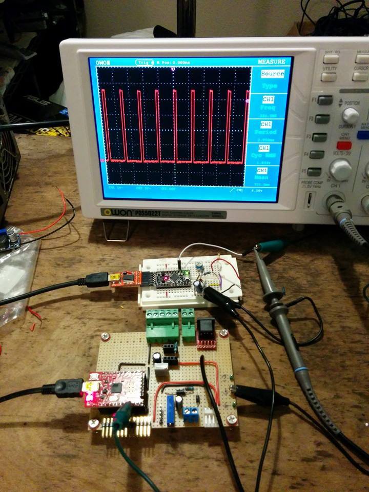
I decided to try interrupts and a counter to measure the time between pulses. This was fairly easy to get up and running, and I was able to test by simulating the tach signal with an Arduino. It is very accurate, measures down to 29 RPM with a 16-bit counter, and updates every time it gets a pulse. Utilizing the 16-bit timer for tach eliminates my need for
I realized late while prototyping the hardware that I needed to measure the voltage I was feeding the sensors (Vsen) so I could compensate for fluctuations in my power supply. When I decided to use the AVR’s internal Aref regulator, the AD’s reference voltage no longer varied along with Vsen (+-0.1v variation on Vsen == +-4% skew in my readings). Another multi-turn pot voltage divider allowed me to read my 5v rail and a little math integrated this value to increase my accuracy.
Protection
Piping dirty voltages into a critical safety system is a little nerve racking. We must be able to handle a sensor input shorting to ground, going open, or getting hit with a big voltage spike.
Handling shorts is a matter of picking a sense resistor large enough to prevent a short from resulting an overcurrent condition. At 5v, the smallest planned sense resistor of 470ohm will result in a short current of 10mA.
Overvoltage protection is a little trickier, but still fairly simple. Using zener diodes to shunt excess voltage on the sensor inputs, and transient-voltage-suppression (TVS) diodes on the engine voltage and tach inputs, we are fairly well protected. If you are wondering why I used zeners in one place and TVS in the other, I don’t have one. The schematics I found online tended to use zeners on lower voltage inputs and TVSes on the higher voltage ones. I wanted to try both so I did.
Discussions
Become a Hackaday.io Member
Create an account to leave a comment. Already have an account? Log In.