 Jonathan Buchanan
I actually got the parts a few days ago, but I had to wait to fully assemble the thing because of an unexpected problem.
I eagerly poured the bags out on my desk...
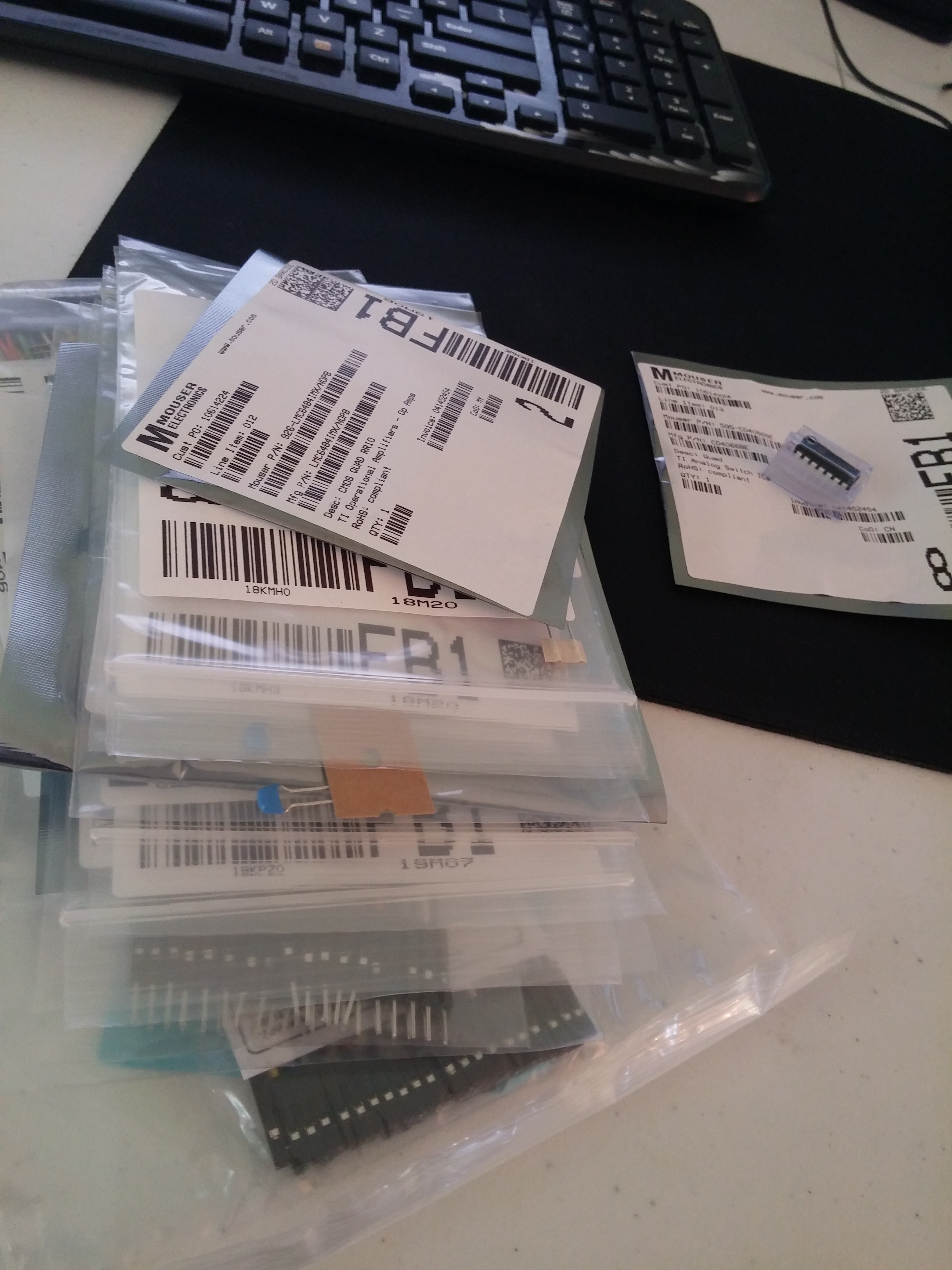
but when I got to the opamps and voltage regulators...
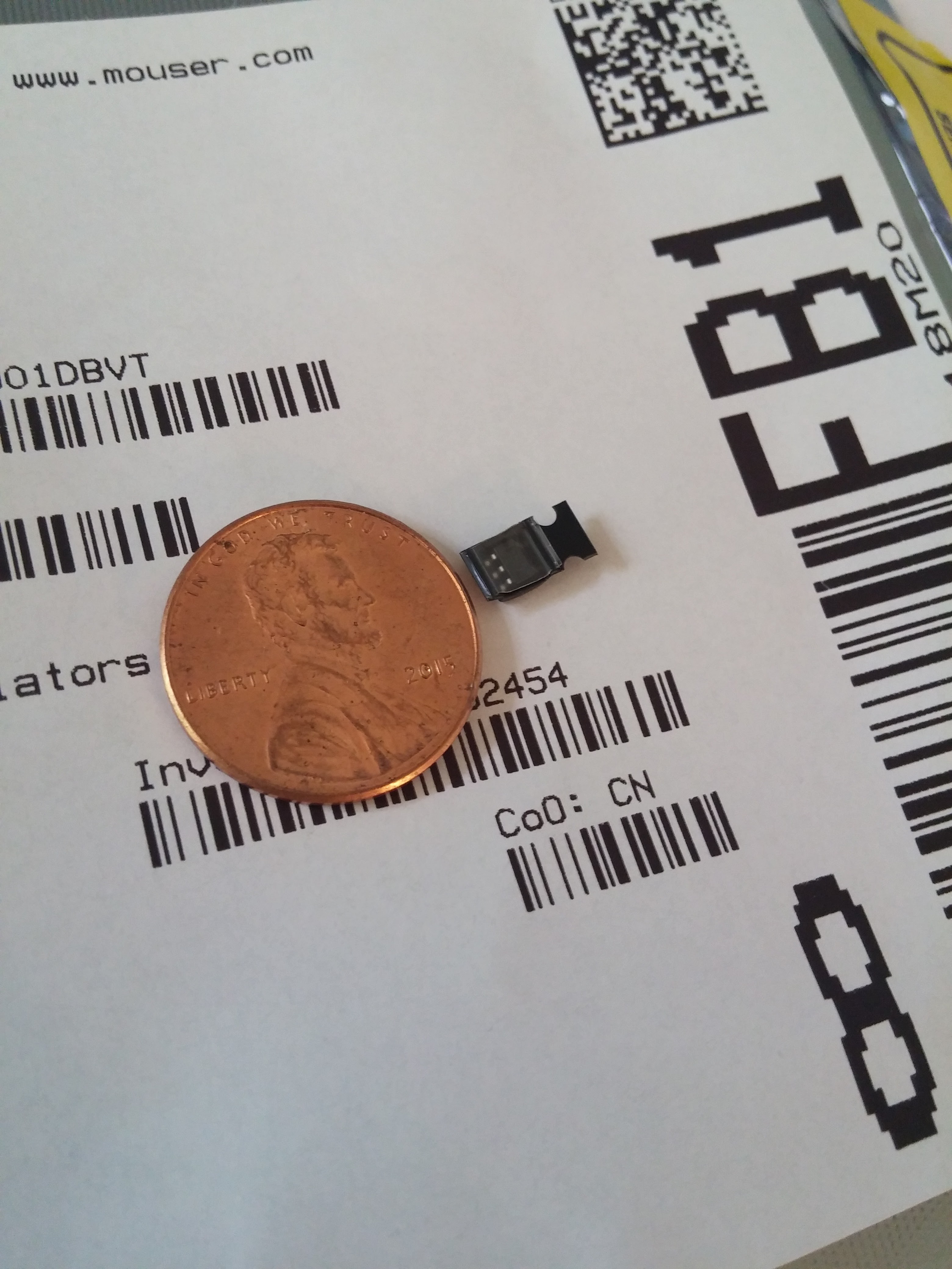 | 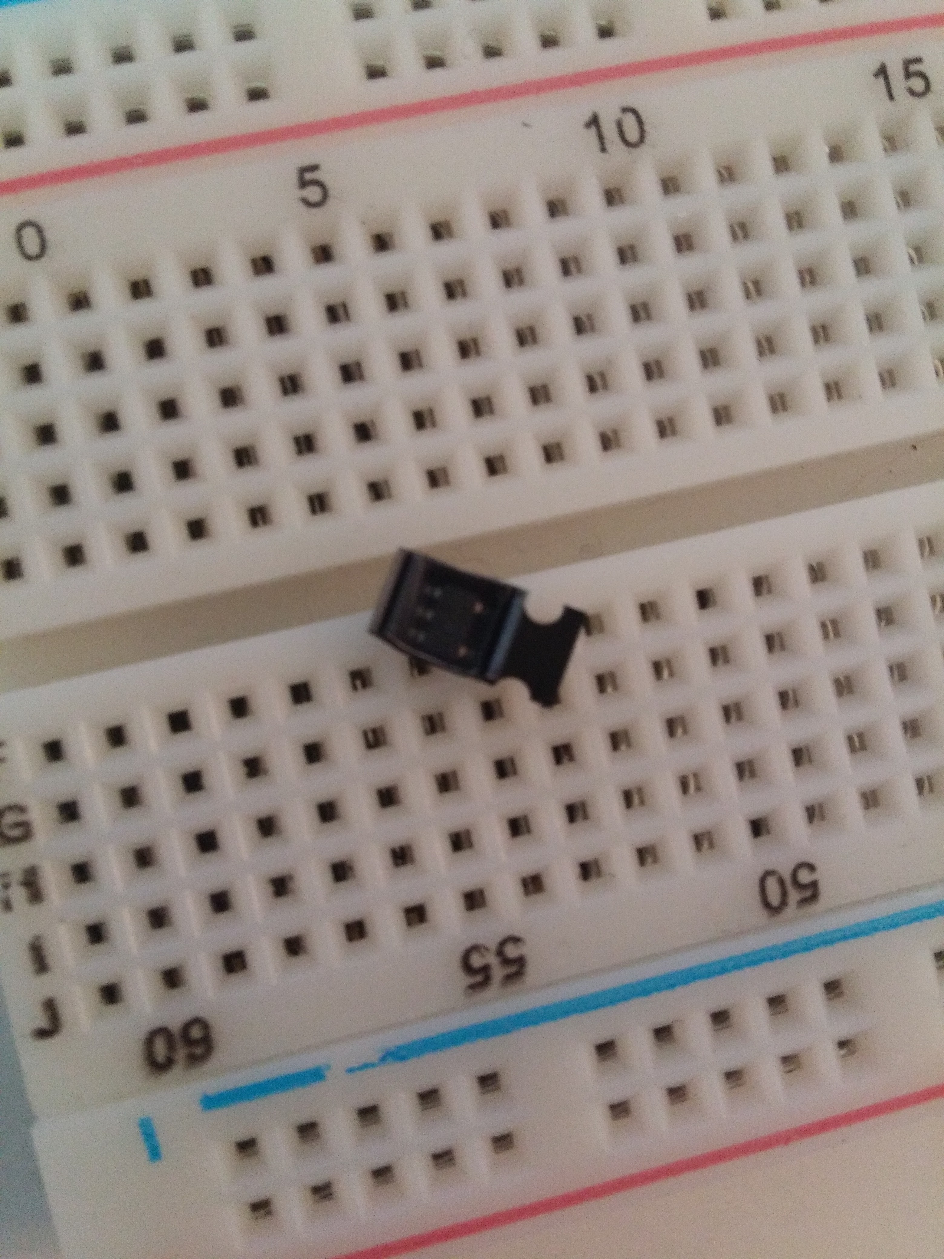 |
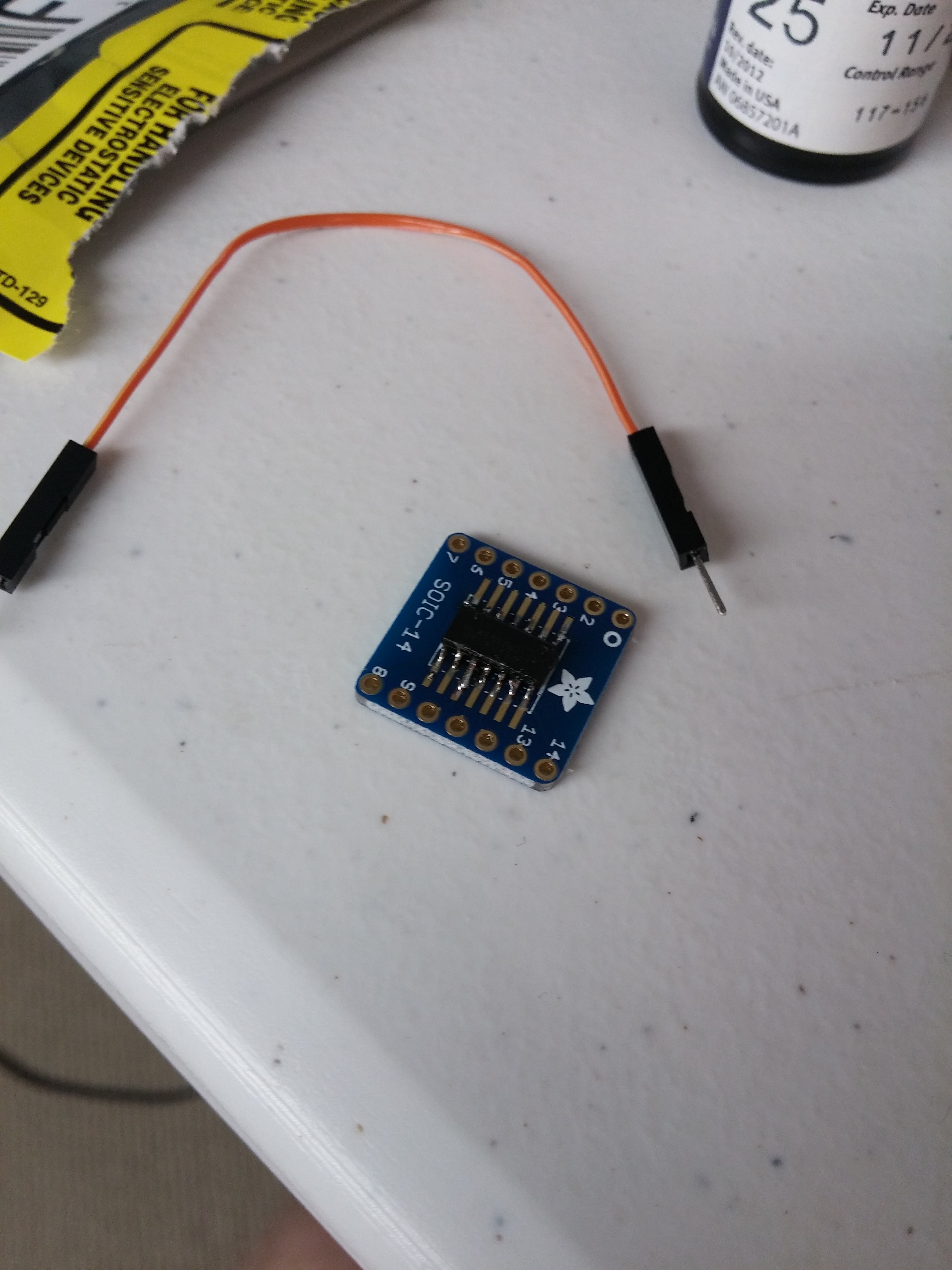
I discovered a slight discrepancy between the pins on the chips and the holes on my breadboard. That was the day I fully learned the difference between breadboard chips and surface mount chips. I felt a little better about myself when I discovered Mouser did not have the voltage regulators in the size I needed (so I couldn't have gotten it right), and I felt better about my project when I discovered adafruit's adapter.

This actually wasn't the right size for the voltage regulators either, but since they had fewer pins and were spaced farther apart, I was able to make the adapters work with them without spending extra money.
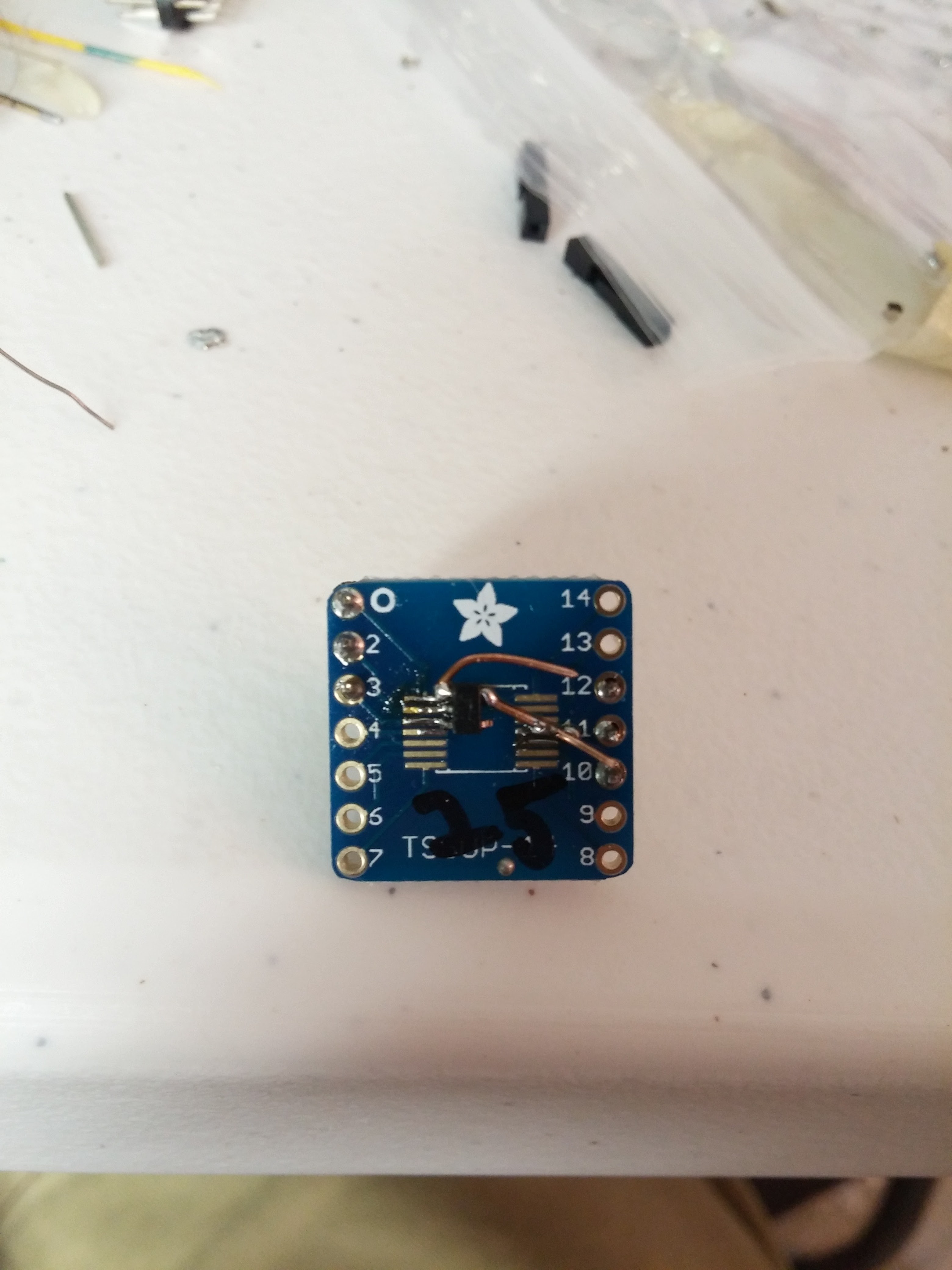 |  |
Before the adapters arrived, I actually made an attempt at fabricating an adapter by using my Grandfather's idea of finding a suitably threaded bolt to space the wires.
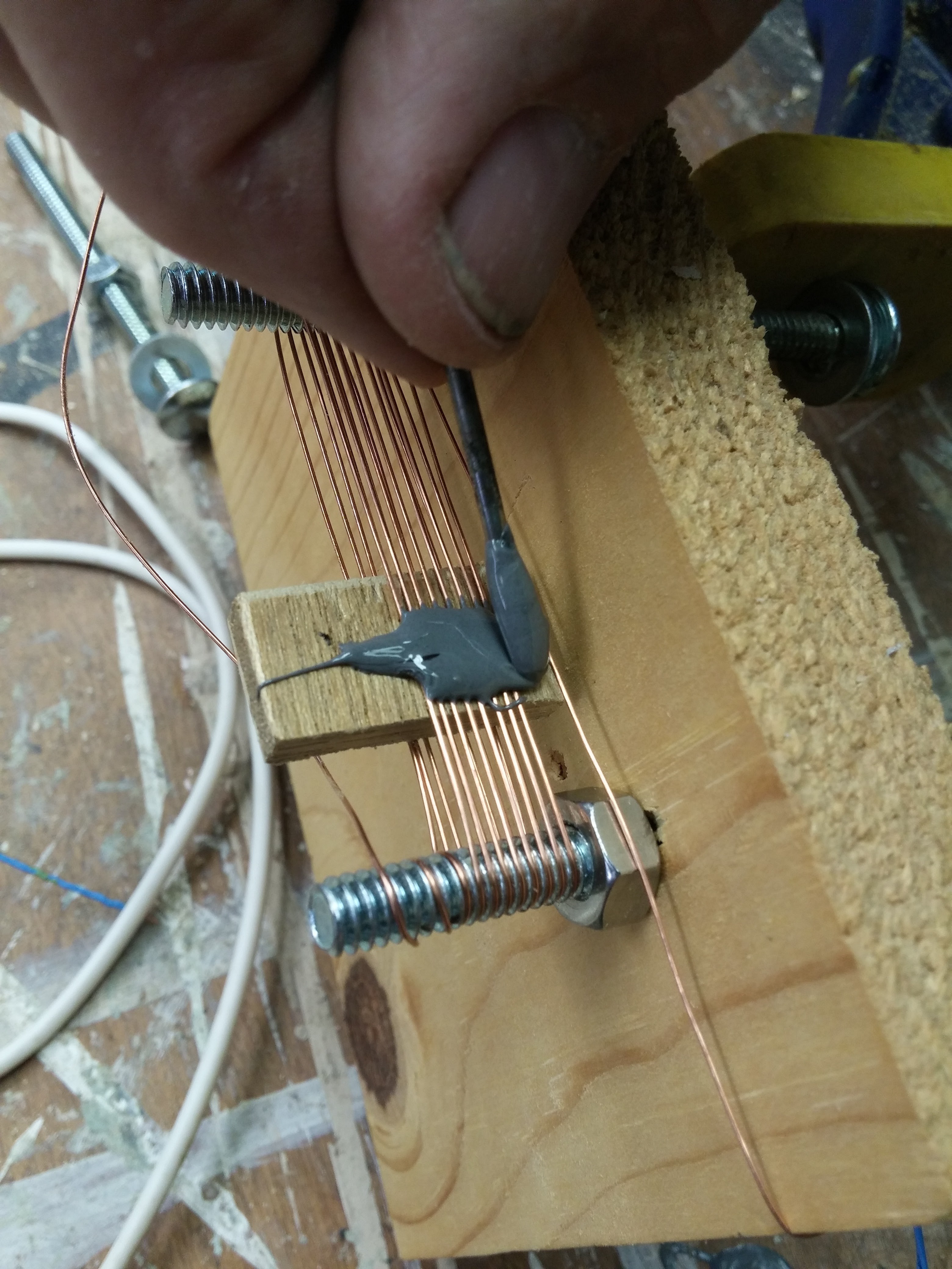
The opamp chip was supposed to sit on the narrow end of the board and the wires would be trimmed down to make connection points. The spacing was good, but even after more than one hour of soldering, I couldn't be sure it was making a good connection. I ended up using the same adapter for it. It took about 5 minutes to solder.
The capacitors and resistors were easier to deal with. Aside from having to look up with way the polarized capacitors should go, I was able to pretty much plug stuff in from the diagram.
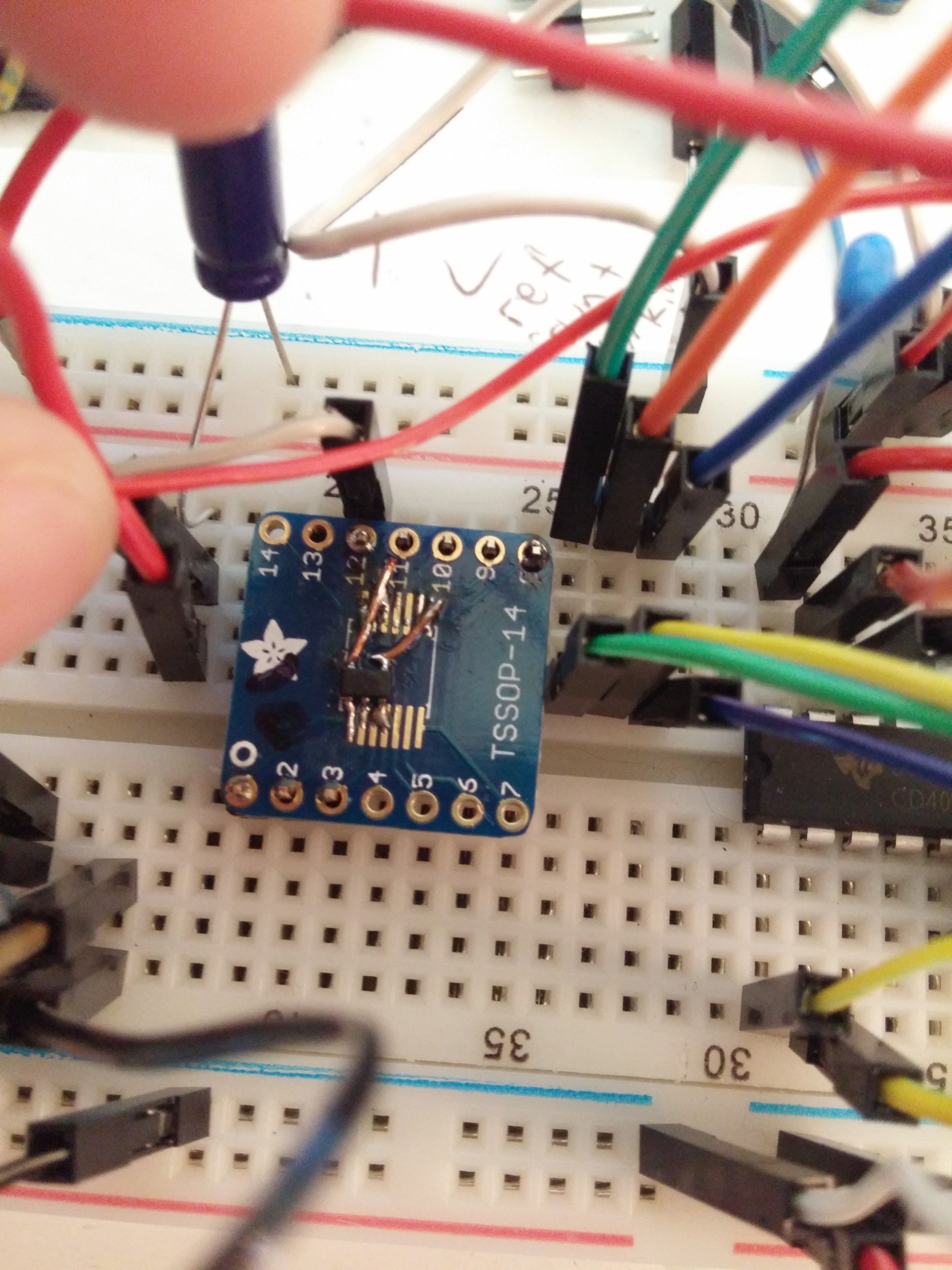
Here is a picture of the final product.

The opamp is on stilts because I didn't have enough space for the wide adapter on the breadboard. To the left of it is the quad switch, then the two voltage regulators. The ADC is behind the breadboard, obscured by wires, and the pi 3 is providing power and reading the ADC.
Now that everything was in place I could test the two voltage regulators.
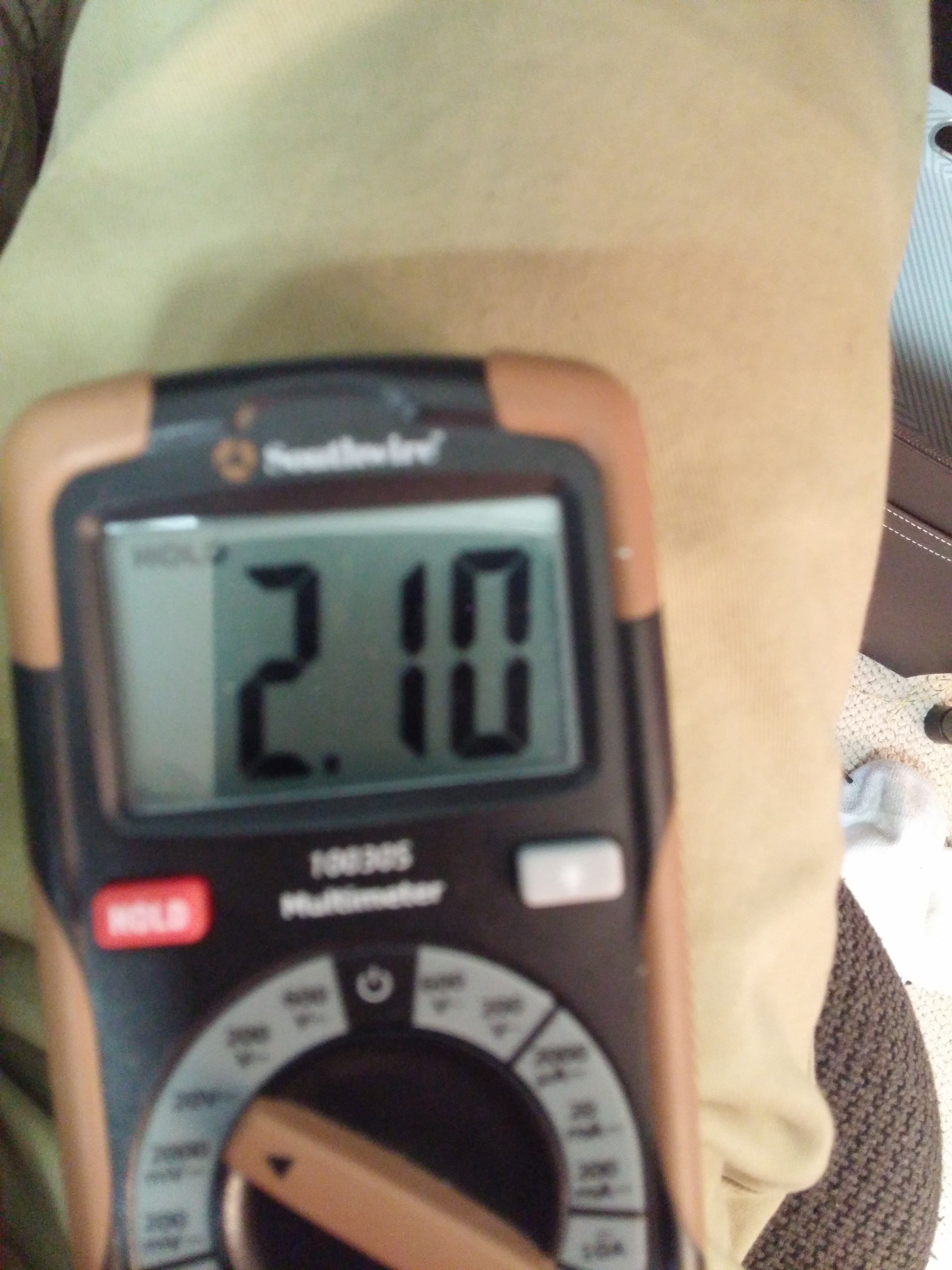 | 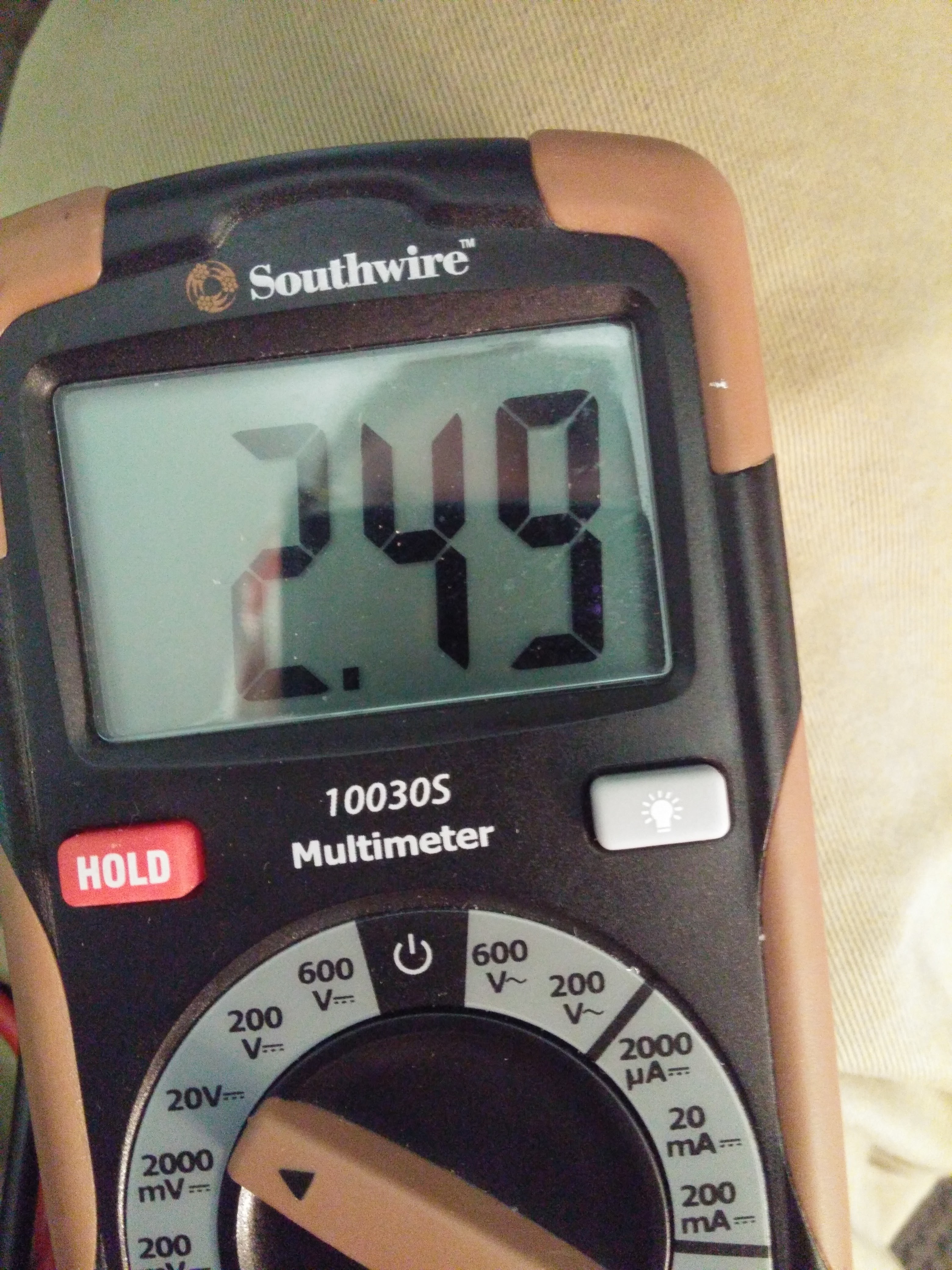 |
The were supposed to be 2.1v and 2.5v respectively, so that was a success.
Testing the whole thing in the next log!
Discussions
Become a Hackaday.io Member
Create an account to leave a comment. Already have an account? Log In.