As with most new PCB layout's, there are things that can be improved upon. Traces sometimes need to be cut or a mod wire is needed. Fortunately, only a Dremel tool was need on the Rev A version of the LED lighting controller. There are enough other issues that a “Rev B” was made.
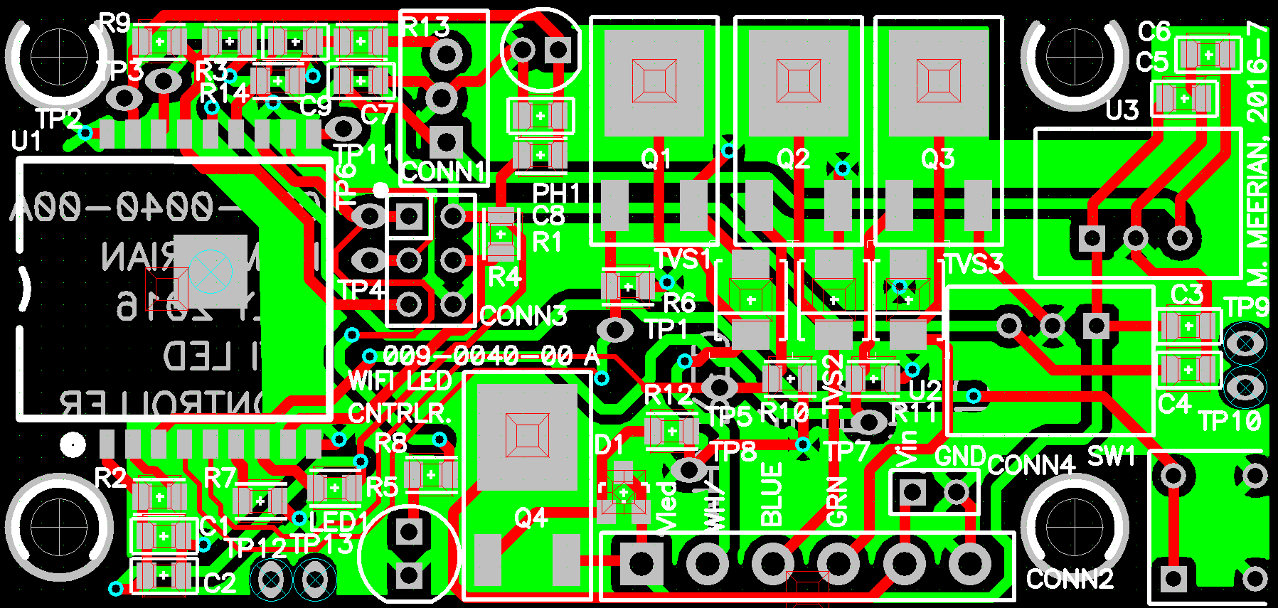
Figure 1: a screen capture of Rev A (red is the top copper and green is the bottom copper)
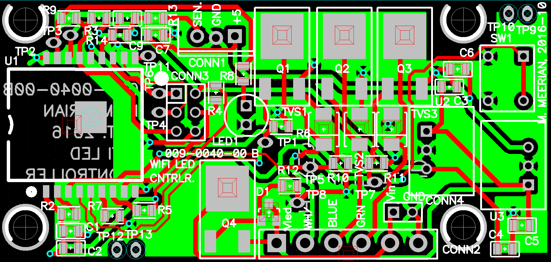
Figure 2 a screen capture of Rev B.
Here is the list of 6 items Rev B addressed:
1) The hole spacing on the PCB is not correct for the bud enclosure. The Y spacing is 1.075” and it should be 1.10” spacing. (completed)
2) The photocell (PH1) and supporting circuitry (C8 and R1) were removed. The photocell circuitry was not used on Rev A. This made room for the ICP header to not hit the IR sensor header when both are being used. (completed)
3) Move the LED indicator pin from the TX line to pin 17 (IO16) on the ESP8266 module. (completed)
4) The pushbutton switch was moved to the edge of the PCB across from the terminal block. This is to put the manual override switch closer to the user and keep the wires away from the user’s hand. (completed)
5) The pushbutton hits the wall of the enclosure. Move the switch away from the edge. (completed) (on the rev A version, a Dremel tool was used on the mounting holes to slide the PCB over some so the switch would fit in the enclosure)
6) +5V, GND, and SEN. labels were added to the 3 pin IR sensor header. (completed)
The new schematic, BOM, PCB layout, and gerbers are in the files section.
file name:
2016-10-3, schematic and PCB layout, under cabinet LED.zip
Discussions
Become a Hackaday.io Member
Create an account to leave a comment. Already have an account? Log In.